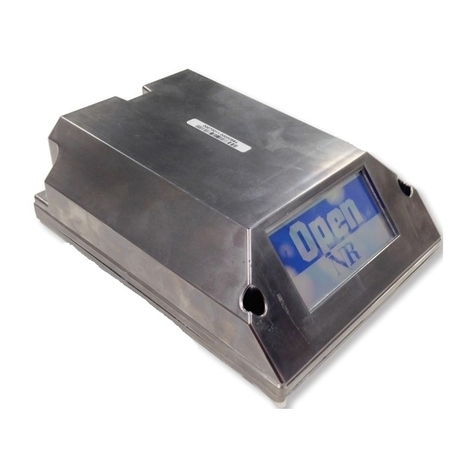
S&C GridMaster User manual

August 19, 2019
© S&C Electric Company 2019, all rights reserved Instruction Sheet 1025-510
GridMaster®Microgrid Control System Panel Mounting Configuration
Installation
Table of Contents
Section Page Section Page
Introduction
Qualified Persons ........................... 2
Read this Instruction Sheet ................... 2
Retain this Instruction Sheet. . . . . . . . . . . . . . . . . . . 2
Proper Application .......................... 2
Operating Considerations..................... 2
Special Warranty Provisions................... 3
Warranty Qualifications ...................... 3
Safety Information
Understanding Safety-Alert Messages........... 4
Following Safety Instructions .................. 4
Replacement Instructions and Labels ........... 4
Safety Precautions ......................... 5
Shipping and Handling
Inspection ................................. 6
Packing ................................... 6
Installation
Before Starting ............................. 7
Mounting the Panel-Mounted GridMaster Controller
Inside the Enclosure....................... 8
Making the Control Power, Data, and GPS
Connections ............................. 9
Final Setup and Checkout ....................14
Appendix
General Specifications .......................15
Module Pinouts .............................15

2 S&C Instruction Sheet 1025-510
Introduction
Qualified Persons WARNING
Only qualified persons who are knowledgeable in the installation, operation, and
maintenance of overhead and underground electric power transmission equipment
and distribution substation equipment, along with all associated hazards, may install,
operate, and maintain the equipment covered by this publication. A qualified person
is someone who is trained and competent in:
• The skills and techniques necessary to distinguish exposed live parts from nonlive
parts of electrical equipment
• The skills and techniques necessary to determine the proper approach distances
corresponding to the voltages to which the qualified person will be exposed
• The proper use of special precautionary techniques, personal protective equipment,
insulating and shielding materials, and insulated tools for working on or near
exposed energized parts of electrical equipment
These instructions are intended ONLY for such qualified persons. They are not
intended to be a substitute for adequate training and experience in safety procedures
for this type of equipment.
Read this
Instruction Sheet NOTICE
Thoroughly and carefully read this instruction sheet before installing or operating your
GridMaster Microgrid Control System. Familiarize yourself with the Safety Information
and Safety Precautions on pages 4 and 5. The latest version of this publication is
available online in PDF format at sandc.com/en/support/product-literature/.
Retain this
Instruction Sheet
This instruction sheet is a permanent part of your GridMaster Microgrid Control System.
Designate a location where you can easily retrieve and refer to this publication.
Proper Application WARNING
A GridMaster controller is only intended for use in the GridMaster Microgrid Control
System. Application information for the GridMaster Microgrid Control System is listed
in Specification Bulletin 1025-31 and with the system diagram drawings provided by
S&C Electric Company.
Operating
Considerations
A GridMaster Microgrid Control System enables intelligent electronic devices to be
incorporated into a microgrid. Each GridMaster controller operates as a member of a peer-
to-peer network that ensures electrical demand is met while eliminating single points of
failure. GridMaster controllers are used to monitor and switch new or existing renewable
sources of energy such as wind and solar; critical and non-critical loads (prioritized load
shedding); utility and non-utility sources of generation; and energy storage to allow for
islanding of electrical loads. The GridMaster controller is also capable of recognizing
when devices and equipment are unavailable and can compensate for such contingencies.
The GridMaster controller operates in tandem with the controls of its associated intel-
ligent electronic device (IED). It does not directly provide switching capabilities but does
interface with the IED controls to do so. It is powered through a connection with the IED
and may be supplied with an optional backup battery system. For more information on
the operation of the GridMaster Microgrid Control System, see S&C Instruction Sheet
1025-530, “S&C GridMaster ® Microgrid Control System: O peration.”
S&C Instruction Sheet 1025-510 3
Introduction
Special Warranty
Provisions
The standard warranty contained in the seller’s standard conditions of sale, as set forth
in Price Sheet 150, applies to GridMaster Microgrid Control System, except that the rst
paragraph of said warranty is replaced by the following:
(1) General: The seller warrants to the immediate purchaser or end user for a period
of 10 years from the date of shipment that the equipment delivered will be of the
kind and quality specified in the contract description and will be free of defects of
workmanship and material. Should any failure to conform to this warranty appear
under proper and normal use within 10 years after the date of shipment the seller
agrees, upon prompt notification thereof and confirmation that the equipment has
been stored, installed, operated, inspected, and maintained in accordance with
recommendations of the seller and standard industry practice, to correct the non-
conformity either by repairing any damaged or defective parts of the equipment
or (at the seller’s option) by shipment of necessary replacement parts. The seller’s
warranty does not apply to any equipment that has been disassembled, repaired, or
altered by anyone other than the seller. This limited warranty is granted only to the
immediate purchaser or, if the equipment is purchased by a third party for instal-
lation in third-party equipment, the end user of the equipment. The seller’s duty to
perform under any warranty may be delayed, at the seller’s sole option, until the
seller has been paid in full for all goods purchased by the immediate purchaser.
No such delay shall extend the warranty period. Replacement parts provided by
the seller or repairs performed by the seller under the warranty for the original
equipment will be covered by the above special warranty provision for its duration.
Replacement parts purchased separately will be covered by the above special war-
ranty provision.
Warranty
Qualifications
Warranty of GridMaster Microgrid Control System is contingent upon the installation,
conguration, and use of the control and software in accordance with S&C’s applicable
instruction sheets. This warranty does not apply to major components not of S&C
manufacture, such as batteries, communication devices, and the IED associated with
the controller. However, S&C will assign to the immediate purchaser or end user all
manufacturers’ warranties that apply to such major components.

4S&C Instruction Sheet 1025-510
Safety Information
Understanding
Safety-Alert
Messages
Several types of safety-alert messages may appear throughout this instruction sheet and
on labels and tags attached to your GridMaster Microgrid Control System. Familiarize
yourself with these messages and the importance of these signal words:
DANGER
“DANGER” identifies the most serious and immediate hazards that will likely result in
serious personal injury or death if instructions, including recommended precautions,
are not followed.
WARNING
“WARNING” identifies hazards or unsafe practices that can result in serious personal
injury or death if instructions, including recommended precautions, are not followed.
CAUTION
“CAUTION” identifies hazards or unsafe practices that can result in minor personal
injury if instructions, including recommended precautions, are not followed.
NOTICE
“NOTICE” identifies important procedures or requirements that can result in product
or property damage if instructions are not followed.
Following Safety
Instructions
If you do not understand any portion of this instruction sheet and need assistance, contact
your nearest S&C Sales Ofce or S&C Authorized Distributor. Their telephone numbers
are listed on S&C’s website sandc.com, or call the S&C Global Support and Monitoring
Center at 1-888-456-1100.
NOTICE
Read this instruction sheet thoroughly and carefully
before installing your GridMaster Microgrid Control
System.
Replacement
Instructions
and Labels
If additional copies of this instruction sheet are needed, contact your nearest S&C
Sales Ofce, S&C Authorized Distributor, S&C Headquarters, or S&C Electric Canada
Ltd. The latest version is available online in PDF format at sandc.com/en/Support/
Product-Literature/.
It is important that any missing, damaged, or faded labels on the equipment be replaced
immediately. Replacement labels are available by contacting your nearest S&C Sales
Office, S&C Authorized Distributor, S&C Headquarters, or S&C Electric Canada Ltd.

Safety Precautions
DANGER
The GridMaster Microgrid Control System may be installed in equipment that
operates at high voltage. Failure to observe the precautions below will result
in serious personal injury or death.
Some of these precautions may differ from your company’s operating procedures
and rules. Where a discrepancy exists, follow your company’s operating procedures
and rules.
1. QUALIFIED PERSONS. Access to the GridMaster
Microgrid Control System must be restricted only to
qualified persons. See the “Qualified Persons”
section on page 2.
2. SAFETY PROCEDURES. Always follow safe
operating procedures and rules.
3. PERSONAL PROTECTIVE EQUIPMENT. Always
use suitable protective equipment, such as rubber
gloves, rubber mats, hard hats, safety glasses, and
flash clothing, in accordance with safe operating
procedures and rules.
4. SAFETY LABELS AND TAGS. Do not remove or
obscure any of the “DANGER,” “WARNING,”
“CAUTION,” or “NOTICE” labels and tags. Remove
tags ONLY if instructed to do so.
5. ENERGIZED COMPONENTS. Always consider all
parts live until de-energized, tested, and grounded.
6. MAINTAINING PROPER CLEARANCE. Always
maintain proper clearance from energized
components.
S&C Instruction Sheet 1025-510 5

6S&C Instruction Sheet 1025-510
Inspection
Examine the shipment for external evidence of damage as
soon after receipt as possible, preferably before removal
from the carrier’s conveyance. Check the bill of lading to
make sure all listed shipping skids, crates, and containers
are present. If there is visible loss or damage:
1. Notify the delivering carrier immediately.
2. Ask for a carrier inspection.
3. Note the condition of shipment on all copies of the
delivery receipt.
4. File a claim with the carrier.
If concealed damage is discovered:
1. Notify the delivering carrier within 15 days of receipt of
shipment.
2. Ask for a carrier inspection.
3. File a claim with the carrier.
Also, notify S&C Electric Company in all instances of
loss or damage.
Packing
A complete GridMaster Microgrid Control System consists
of the following components:
• The GridMaster controller
• This Instruction Manual
Shipping and Handling

S&C Instruction Sheet 1025-510 7
Installation
Figure 1. The GridMaster controller.
LED Power Indicator
Power/
Ethernet
Module
Serial
Module
Power
Switch
Before Starting
WARNING
These instructions do not replace the need for
utility operation standards. Any conflict between the
information in this document and utility practices
should be reviewed by the appropriate utility personnel
and a decision made as to the correct procedures to
follow.
A GridMaster Microgrid Control System is connected
to equipment that may be operating at primary
voltage levels. High voltage may be present in the
wiring to the equipment’s intelligent controls or to
the equipment itself during certain failures of the
equipment’s wiring or grounding system, or due to a
failure of the equipment itself. For this reason, access
to the GridMaster controller should be treated with the
same safety precautions that would be applied when
accessing other high-voltage lines and equipment.
Follow all locally approved safety procedures when
working on or around the controller.
Before attempting to access an existing equipment
installation, check carefully for visible or audible signs
of electrical or physical malfunction. Do this before
touching or operating the GridMaster controller or
any other part of the installation. These warning
signs include such things as smoke, fire, open fuses,
crackling noises, loud buzzing, etc. If a malfunction
is suspected, treat all components of the installation,
including the GridMaster controller and associated
mounting hardware, as though they were elevated to
primary (high) voltage.
Whenever accessing or performing maintenance
on the GridMaster controller, follow your company’s
operating procedures to disable automatic operation
of the equipment to prevent unexpected operation of
the equipment.
Familiarize yourself with the parts of a GridMaster
controller. See Figure 1.
Digital I/O
Module

8S&C Instruction Sheet 1025-510
Installation
Figure 2. A GridMaster controller dimensional drawing.
Mounting the Panel-Mounted GridMaster
Controller Inside the Enclosure
Panel-mounted GridMaster controllers can be installed in
a wide-variety of enclosures. When the associated IED is
provided by S&C Electric Company, the controller may be
factory-installed inside the gear’s low-voltage enclosure.
The panel-mounted GridMaster controller is 14 inches
(356 mm) high, 9.25 inches (235 mm) wide, and 3.82 inches
(97 mm) deep, flange mounted with 3/8-inch (9.5-mm)
diameter mounting holes. The microgrid controller should
be mounted in “open-construction” style so it may be easily
connected to and serviced without requiring removal of
the controller or surrounding equipment. The GridMaster
controller should be mounted in an appropriate NEMA
enclosure (or equivalent) for protection from weather, dust,
and unintentional intrusion. When mounting the control-
ler on a swing-out panel, make sure any communications
cables are trained and/or harnessed in such a way move-
ment of the panel will not loosen the connections.
To mount the GridMaster controller to the enclosure:
STEP 1. Tap four holes at the positions shown in Figure
2 on an interior panel of the NEMA enclosure.
The mounting holes have a ⅜-inch (9.5-mm)
diameter.
STEP 2. Use a mounting screw appropriately sized for a
⅜-inch (9.5-mm) hole and a at washer to secure
the controller inside the enclosure. When
considering placement, make sure there is
enough room to allow for the cables to protrude
from the face of the controller.
356 mm
330 mm
235 mm
210 mm
97 mm
83 mm

S&C Instruction Sheet 1025-510 9
Installation
Figure 3. An Power/Ethernet module
Making the Control Power, Data, and
GPS Connections
Power/Ethernet Module
A GridMaster Microgrid Control System comes standard
with a Power/Ethernet Module that provides connections
for power, an intruder detection switch, Ethernet
communications, and a coaxial port for connecting a GPS
antenna. See Figure 3. The Door Intrusion feature will be
explained in the “Installing Enclosure Intrusion Detection”
section on page 13. Pinouts are shown in the “Module
Pinouts” section starting on page 15.
Complete the following steps to connect to the Power/
Ethernet Module:
STEP 1. If present, connect the IED’s GPS antenna to the
female coaxial connector on the controller.
STEP 2. Connect a solid-copper Ethernet cable to the
Ethernet 0 port on the controller. The other end
of the cable may be connected to either a radio,
a network switch, or directly to the local-area
network on which the GridMaster Microgrid
Control System will be interconnected.
STEP 3. The GridMaster controller can accept control
power between 9 and 36 Vdc. Connect the two
12 –30 AWG wires from the control power source
to the GridMaster controller to the rst two
(left-hand facing) screw terminals. Input power
must be 9 to 36 Vdc.
S&C recommends the control power source
be supported by a uninterruptable power supply
that can power the controller for at least one hour
after control power is lost.
STEP 4. If the associated IED communicates via
Ethernet, connect a solid-copper Ethernet cable
to the Ethernet 1 port. Connect the other end to
the IED according to the IED manufacturer’s
instructions.

10 S&C Instruction Sheet 1025-510
Installation
Figure 4. An RS-485 connector module.
RS-485 Connector Module
A three-terminal RS-485 connector module comes
standard with the GridMaster controller. See Figure 4. This
module provides three RS-485 screw terminals with six
ports. Pinouts are shown in the “Module Pinouts” section
starting on page 15.
To connect to a RS-485 connector module, connect
three 12– 30 AWG wires to the screw terminals associated
with the desired port and tighten the screws until they bot-
tom out. Do not leave the wires unsecured. The maximum
recommended length of wire is 1000 meters (3281 feet).
There is no required order for use of the screw terminals.
When using stranded wire, S&C recommends coating the
stranded ends with tin-solder before insertion into the
screw terminals.
Note: The RS-485 connector module can communicate
at speeds up to 115200 baud and can be used to acquire
data from any compatible IED, including those using the
Modbus protocol. Third-party converters are available to
convert from RS-485 to RS-232 or RS-422.
All ports are configured as Data Terminal Equipment
(DTE). Both the send and receive registers of each port
have a 16-byte-first-in, first-out (FIFO) and ports have
16C550-compatable universal asynchronous receiver/
transmitters (UARTs). Individual modem handshake con-
trol signals are supported for all ports.

S&C Instruction Sheet 1025-510 11
Installation
Figure 5. A digital input/output module.
Figure 6. Adding an interposing relay to the circuit.
Digital Input/Output Module
This optional digital port is available for running low-
voltage inputs and outputs to the microgrid controller.
See Figure 5. These ports are optically isolated from the
internal computer for protection. These ports can be used
to secure machine-to-machine communication without the
need for direct computer-based connections:
• Digital outputs
• Pulled low to VSS to change state
• Left open for the opposite state
• Digital outputs sink capacity = 10 mA
• On-board 5-Vdc current = 50 mA
The screw terminals can accept 14 to 24 AWG wire.
When using stranded wire, S&C recommends coating
the stranded ends with tin-solder before insertion into
the screw terminals. Pinouts are shown in the “Module
Pinouts” section starting on page 15.
In addition to measuring and sourcing transistor-
transistor logic (TTL) signals, these ports can be used
for driving higher voltage relays. This can be done either
through an interposing relay using a circuit such as the one
shown in Figure 6 or through any number of commercially
available logic-level driven relays. Contact S&C Electric
Company for assistance in connecting this type of port to
a relay circuit. Vdc
Vdc

12 S&C Instruction Sheet 1025-510
Installation
Figure 7. A CAN port module.
Figure 8. An analog IO port module.
CAN Port Module
This optional module connects with devices that use the
Controller Area Network (CAN) protocol for transmitting
data and receiving commends. See Figure 7. This module
provides two high-speed CAN channels (ISO 11898-2) and
transmits data at 33 kbd up to 1 Mbd, depending on the
length of line.
The screw terminals can accept 14 to 24 AWG wire.
When using stranded wire, S&C recommends coating
the stranded ends with tin-solder before insertion into
the screw terminals. Pinouts are shown in the “Module
Pinouts” section starting on page 15.
Analog IO Port Module
This module provides input and output ports to measure
and issue analog signals. See Figure 8. This module
accommodates up to 4 different analog measurements
between -10 and +10 Vdc. The two analog outputs can
source 4 to 20 mA into 1000 ohms. For the specific
application information on these optional ports, contact
S&C Electric Company.
The screw terminals can accept 14 to 24 AWG wire.
When using stranded wire, S&C recommends coating
the stranded ends with tin-solder before insertion into
the screw terminals. Pinouts are shown in the “Module
Pinouts” section starting on page 15.

S&C Instruction Sheet 1025-510 13
Installation
Figure 9. Connect the leads for the intrusion-detection
alarm.
Installing Enclosure Intrusion Detection
When supplied by S&C, the intrusion detection contacts
will be connected to a magnetic reed switch installed on
the door of the enclosure. This switch will be pre-installed
on the enclosure door. When the door is opened, the
contact inside the reed switch is made and the microgrid
controller will detect an open door.
To connect the reed switch to the microgrid controller:
Attach the leads from the reed switch to the two right-hand
screw terminals on the power/Ethernet module. See Figure
9. The leads can be connected to the screw terminals in
any order

14 S&C Instruction Sheet 1025-510
Installation
Figure 10. The GridMaster Microgrid Control System door alarm pop-up.
Final Setup and Checkout
Before switching on and configuring the GridMaster
Microgrid Control System according to the instructions
in S&C Instruction Sheet 1025-530, check the following:
STEP 1. Make sure the GridMaster controller is securely
installed in the enclosure. Check all fasteners
for tightness.
STEP 2. Make sure all cable connections and wiring
connections to the GridMaster controller are
secure. If the controller is connected to a swing-
out panel, make sure the cables are trained and/
or harnessed so movement of the panel will not
loosen the connection.
STEP 3. Turn on the control power to the GridMaster
controller by toggling the ON switch in the
upper right-hand corner of the control to the On
position. The power indicator will illuminate.
STEP 4. Open a browser window and connect to the
network to which the controller is connected.
Connect to the controller by entering the
address andlog-in credentials securelysupplied
to you by S&C Electric Company. Detailed log-in
and password-maintenance information can be
found in S&C Instruction Sheet 1025-530.
When logged in to the control, check the
functioning of the intrusion-detection system (if
installed) by opening and closing the enclosure
door. When open, the door alarm will appear in
a pop-up window. See Figure 10.

S&C Instruction Sheet 1025-510 15
Appendix
Pin Function
1Data (TX +)
2Data (TX -)
3Data (RX +)
4Ground (-)
5Ground (-)
6Data (RX -)
7Power (+)
8Power (+)
RS-485 Connector Module
General Specifications
Control Voltage 9 to 39 Vdc
Operating Temperature -25°C to 70°C (-13°F to 158°F)
Operating Humidity 95% non-condensing humidity
Altitude 2000 meters (6562 feet)
Module Pinouts
Power/Ethernet Module

16 S&C Instruction Sheet 1025-510
Appendix
CAN Port Module
Analog IO Port Module
Digital Input/Output Module
Vdc
Vdc
Vdc
Vdc
Table of contents
Other S&C Controllers manuals

S&C
S&C IntelliCap User manual

S&C
S&C TripSaver II User manual

S&C
S&C Micro-AT User manual

S&C
S&C PMH Operation and maintenance manual

S&C
S&C BankGuard PLUS User manual

S&C
S&C IntelliCap Plus Operating instructions

S&C
S&C IntelliCap 2000 User manual

S&C
S&C Micro-AT User manual

S&C
S&C BankGuard PLUS Guide

S&C
S&C 6800 Series User manual

S&C
S&C IntelliCap Instruction Manual

S&C
S&C BankGuard PLUS Instruction Manual

S&C
S&C PMH Installation instructions

S&C
S&C Vista Owner's manual

S&C
S&C Micro-AT User manual

S&C
S&C Micro-AT Instruction Manual

S&C
S&C Vista SD Owner's manual

S&C
S&C 5800 Series Operating instructions

S&C
S&C 6800 Series Parts list manual

S&C
S&C 6802 User guide