ESP WITNESS DVR4 User manual

11

2
CONTENTS
Introduction to Digital Video Recorder-----------------------------------------------------------------3
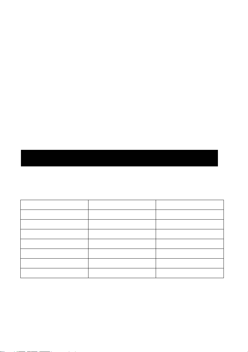
Front panel buttons-----------------------------------------------------------------------------------------4
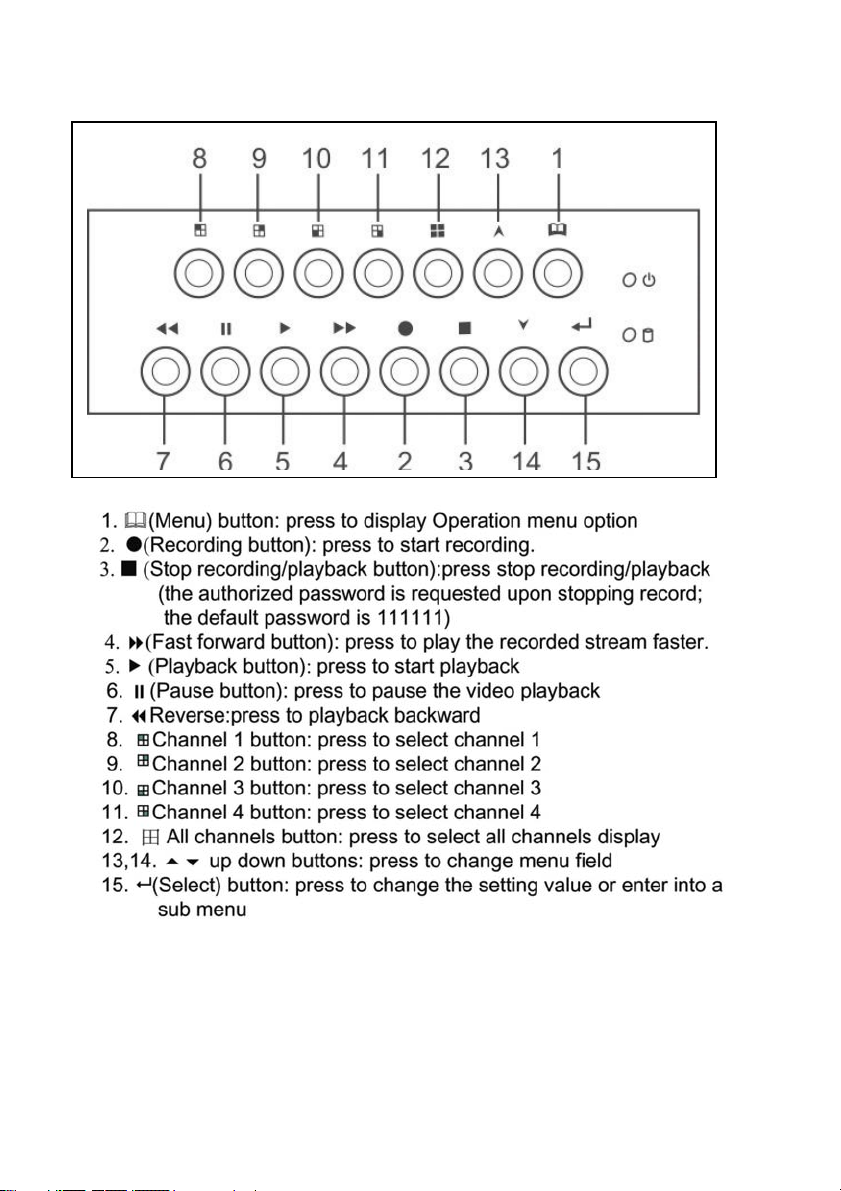
Rear panel buttons------------------------------------------------------------------------------------------5
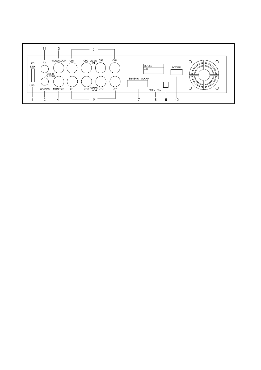
DVR installation: Video Output Connection------------------------------------------------------------6
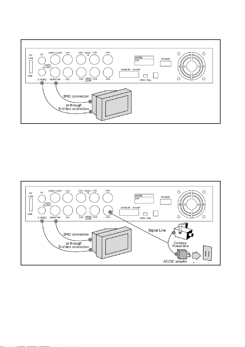
DVR installation: Video Input Connection-------------------------------------------------__----------7
DVR installation: Sensor Installation--------------------------------------------------------------------7
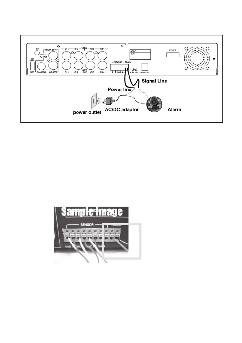
DVR installation: Alarm Installation----------------------------------------------------------------------8
Powering up the DVR---------------------------------------------------------------------------------------9
On-screen display-------------------------------------------------------------------------------------------10
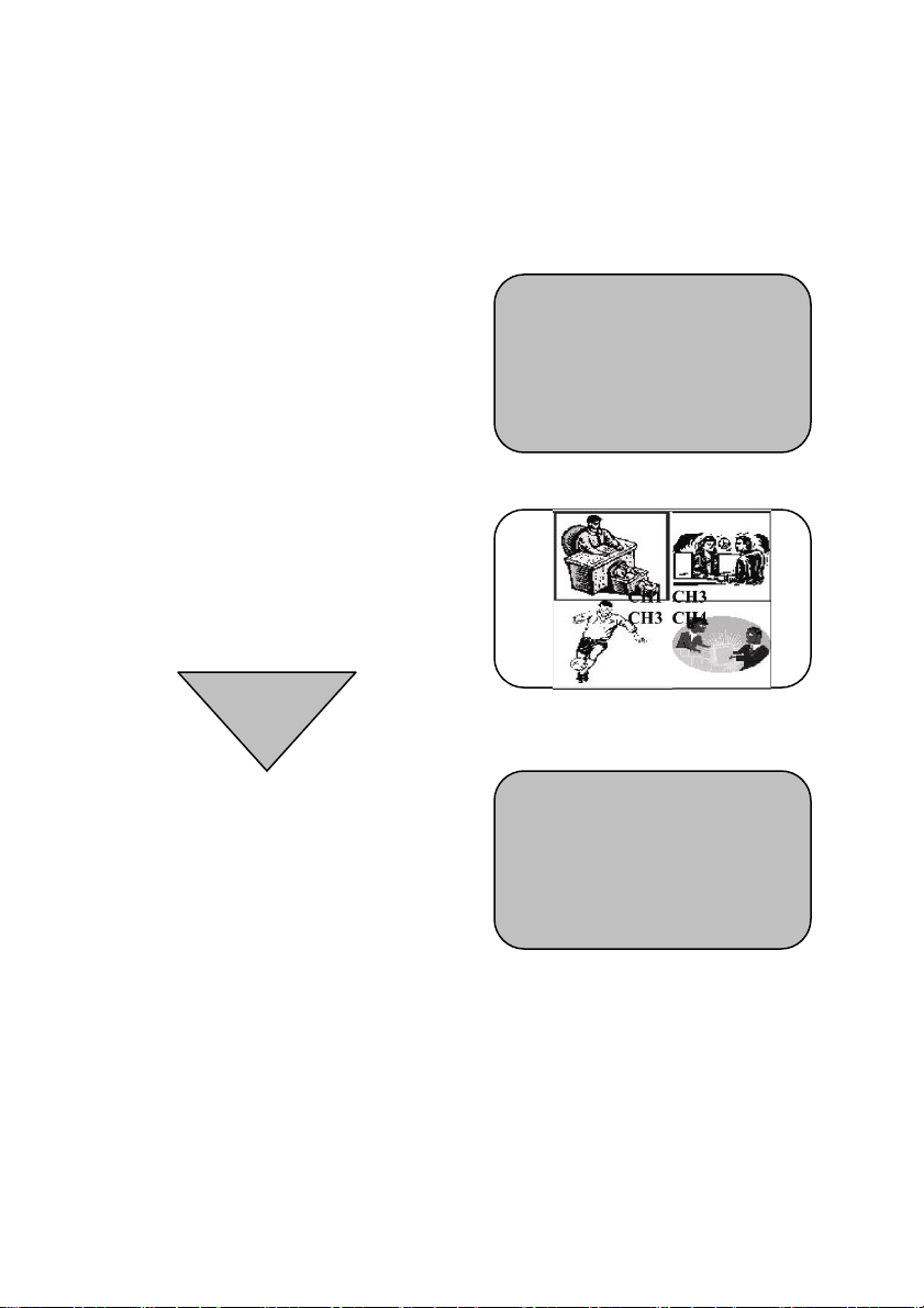
Real-Time display--------------------------------------------------------------------------------------_----11
Operation Guide: Main menu-----------------------------------------------------------------------------12
Operation Guide: Camera selection---------------------------------------------------------------------12
Operation Guide: Record mode--------------------------------------------------------------------------13
Operation Guide: Record frame rate--------------------------------------------------------------------14
Operation Guide: Video quality---------------------------------------------------------------------------15
Operation Guide: Record schedule---------------------------------------------------------------------16
Operation Guide: Sub menu – password change---------------------------------------------------17
Operation Guide: Sub menu – time set ---------------------------------------------------------------18
Operation Guide: Sub menu – display format--------------------------------------------------------18
Operation Guide: HDD setup------------------------------------------------------------------------------19
Operation Guide: Sensor setup (Motion Detection)-------------------------------------------------20
Operation Guide: Playback--------------------------------------------------------------------------------21
Appendix I Regulatory--------------------------------------------------------------------------------------22
Appendix II PC LINK-----------------------------------------------------------------------------------23~25

Introduction
The digital video recorder (DVR) is for recording / retrieving video streams from up to 4
channels at the same time. It adopts a digital image compression technology to
compress the input channel video streams, and uses a HDD (Hard Disk Drive) to
record the compressed video stream.
The following operation guide explains how to operate / manage the DVR and explains
how to install the DVR at your premises and install the HDD into the DVR.
DVR Package
Those following items are supplied with the DVR package. If any are missing, please
contact your supplier.
Item Q’ty Remarks
Stand Alone DVR 1
AC-DC Power Adapter 1
Removable Hard Drive 1 With security KEY
Power Cable 1
User Guide 1
CD Disk 1
USB Line 1 Optional
3

Front Panel
4

Rear Panel
1. PC Link: USB device interface (2.0)
2. S-Video
3. Video output
4. Monitor: Second Video output
5. Video input
6. Video loop-through
7. Sensor input / alarm output: 4 sensor inputs and one alarm output
8. NTSC/PAL switch
9. DC – in (12 volts, 2.0A)
10. Power ON/OFF
11. AV
5

DVR Installation
1. Video Output Connection (TV or Monitor)
Connect a TV (Monitor) to the DVR using one of the video output connectors. The DVR
provides 1x S-Video input and 2 x BNC connector. The above figure shows the video
line connection.
6

DVR Installation
2. Video Input Connection (Camera)
Connect cameras to the DVR using the video input connectors. The DVR provides 4 x
BNC connectors. The camera installation procedures are as follows:
i. Connect the video signal line to the DVR.
ii. Connect power to the camera.
3. Sensor Installation
The DVR has 4 sensor inputs, one for each channel. The sensor Installation procedure
is as follows:
i. Connect the sensor signal line to the unit. The sensor signal terminal is on the
DVR rear panel.
7
ii. Connect the sensor adaptor jack into the sensor, and plug in the power adaptor.

VR Installation
. Alarm Installation
he DVR includes one internal switch for sounding an alarm when any of the sensor
puts is activated. The switch is normally open and closed upon activation. The
rcuitry is shown in the above figure. The alarm is installed as follows:
a power supply, which is normally supplied with the alarm.
.
D
4
T
in
ci
i. The alarm requires
ii. Connect the alarm power line to the alarm switch terminal on the rear of the DVR
8

9
owering up the DVR
nce the DVR has been properly installed (please refer to pages 15-18 for further
etails on DVR installation) the unit is ready to record and display. Apply power and
witch on.
DD , the message shown
on the right will be displayed:
fter initial settings are restored
e message on the right will
e displayed on screen.
urn off the DVR and re-start it.
P
O
d
s
Following power on, the DVR
takes a few seconds checking
the H
HDD CHECKING
OK
The DVR will enter into real-time
Display Mode as shown on the right. 原圖
Turn off the DVR and turn it
back on again.
NOTE
A
th
b
T

On-Screen Display
1. Power on the system
2. Real Time Display
Supports «Each» or «QUAD» on monitor and playback.
«EACH»
Record as full screen video. CH1, CH2, CH3 & CH 4 will be recorded in separate
ecord frames per second based on 7.5fps for each playbac
files for playback. Max. r
10

file. Supports full screen and quad display.
11
«EACH»
Supports both of one channel dispaly on full screen and quad dispaly. When set to
«Each» mode, the displa can be quad or one channel on full screen, so as
h channel per second is 7.5fps.
creen from CH1 to CH4
CH 4 on full screen.
«QUAD»
Supports qua wer resolution
compared with single channel recording.The frame rate ill be higher – Max. 30 fps
EACHMODE Q
Note: MENU b c. Mode
y
playback. Maximum recording frames for eac
zFull S
CH 1 on full screen
d display and quad playback only. Records at a lo
w
(NTSC) and 25fps (PAL).
CH1 (M) HDD Status 1%
2004/06/25 15:30:25
UADMODE
utton can shift to Re

12
Operation guide
MAIN MENU
Presstodisplay
Menu option
Stop recording or playback before entering into OSD menu.
You will be requested to enter the password to stop recording.
CAMERA SELECTION
p a
O er tion Guide
¾
¾
Record Frame Rate: NSTC 30fps
PAL 25fps
The DVR has facility for 4 camera inputs. Use
the channel buttons on the front panel to select
a specified channel for real-time display.
Use “ “ button or channel butt
Example:
1. When you choose (----), all cameras are de-selected.
2. When you choose (1234), all cameras are selected.
3. When you chose (---4), only the fourth camera is selected.
ons for different combinations of channel display.
VIDEO LOSS! and the built-in
sound when there
is no video connection or a connection failure.
“VIDEO LOSS” will be displayed
alarm buzzer will be triggered to
NOTE

13
Channel Display Control
In (回) mode, use the following buttons to display each channel in
full-screen format.
RECORD SELECT
RECORD MODE
Channel 1 button: Full Screen display of channel 1.
Channel 2 button: Full Screen display of channel 2.
Channel 3 button: Full Screen display of channel 3.
Channel 4 button: Full Screen display of channel 4.
NOTE
Options are the same as “CAMERA
SELECTION” options.
Only the chosen camera(s) will record real-time
events during the recording period.
The DVR has 4 cameras inputs. Use the
channel buttons on the front panel to select a
specified channel for real-time display

Operation Guide
There are two kinds of recording mode: 回(each mode;
full screen mode)& 田(quad screen mode).
When set to 回mode, the specified channel is displayed
as full-screen.
When set to 田mode, quad-screen will be displayed.
Please use buttons on front panel to select mode
then press enter to confirm the selection.
There are a number of different frame rate settings.
The DVR is factory set at the highest frame rate.
Please use buttons on the front panel to select
NTSC: 30fps,15fps,10fps,7fps,5fps,4fps,3fps,2fps,1fps
PAL: 25fps,12fps,8fps,6fps,4fps,3fps,2fps,1fps
mode then press enter to confirm the selection.
RECORD FRAMRATE
NOTE RECORD G FRAME RATE TABLE
The highe eo
stream w when it’s played back.
The lowe
HDD.
The following are examples of the recording fps table for a 80GB
HDD.
IN
r the recording frame rate the more natural the vid
ill look
r the recording frame rate the less space is used on the
14

Operation Guide
V
15
IDEO QUALITY
There are 3 different video quality settings :
Low, Normal and High.
Please use buttons on the front panel to
select mode and then enter to confirm
the selection.
NOTE VIDEO Q CA
The higher the video quality the clearer the image will be.
The lower the video quality the less space is used on the
HDD.
The following is the recording time vs video quality settings.
UALITY SETTINGS vs HDD PACITY

Operation Guide
RECORD SCHEDULE
ETTING EXAMPLE
RECORDING
G
Select this option to change a recording
schedule during the day (24-hour period)
Numbers below indicate the time duration in
he DVR only starts
24 hour format.
(T) 24-hour recording.
(S) Motion recording. T
recording when an event (motion, GPLO) is
triggered.
+ S S S S S S - - - - T T T T T T T S S S S S S +
: : : : :
0 6 11 18 24
S
0:00 ~ 7: 00 SENSOR
7:00 ~ 11:00 RECORDING DISABLED
11: 00 ~ 18:00 RECORDING
CORDIN18:00 ~ 24:00 SENSORING RE
Operation guide
NOTE SENSOR RECORDING INSTALLATION (MOTION)
s
nd
NOTE: AUTO RECORD
o Record Function is disabled. Recording will start againIn PC LINK mode the Aut
automatically 55 seconds after the USB cable is disconnected.
The DVR has 4 alarm inputs that can be configured a
normally closed, normally open, motion detection +NC a
motion detection +NO on the “SENSOR SETUP” menu.
(refer to P.19).
16

S
17
UB MENU
the password is mislaid or forgotten press the (∥) Pause button 5 times, which returns the DVR
Select this option to change the password,
r
time/date setting, date format and to enable
the connection between the DVR and PC ove
the USB interface.
PASSWORD CHANGE:
GE” - a password
ge:
it will
Select “PASSWORD CHAN
change input replaces the “SUB MENU” (the
default password is 111111)
hen the new password is accepted, theW
board will flash the following screen messa
PASSWORD changed.
times then theThe message will blink 5
display returns to the SUB MENU.
If the password was not accepted, the un
automatically return to the SUB MENU.
NOTE
If
to the default setting(111111). The password can then be changed again.

Operation Guide
TIME SET
Select this option to change the date and
time.
DATE DISPLAY FORMAT
The DVR has two date formats, these being
yyyy/mm/dd or dd/mm/yyyy, which can be
set according to regional preference.
18

Operation Guide
HDD SETUP
OVERWRITE ENABLED.
continuously
O”. The unit will stop recording once the
ASTER HDD SIZE:
he primary HDD
:
of HDD capacity
AT
data on the
password is requested
d,
“YES”. The DVR will record
and overwrite the recorded data when the
HDD is full.
“N
HDD is full.
M
Indicates the capacity of t
installed in the unit.
MASTER HDD USED
Indicates the percentage
that has been used.
MASTER HDD FORM
Erases all of the recorded
Master HDD.
The authorized
before formatting, after the unit formatte
the following information will appear on the
screen “HDD DISK FORMATTED”
REMARK: the unit is featured with one HDD
only for the time being unless with 1-2 IDE
BUS.
19

Operation Guide
M
20
OTION DETECTION SETUP (SENSOR SETUP)
MOTION RECORDING: setup recording period
ing ch1-ch4
ORMAL-OPEN (N/O):
set from the N/O (normal-open) to the N/C (normal-close),
ORMAL-CLOSE (N/C):
set from the N/C (normal-close) to the N/O (normal-open),
OTION SETUP: click CH 1 ~ CH 4 to have motion detection.
ith motion detection】
detection】
ENSITIVITY (1~9): 1 would be the most easily to trigger on the alarming event, and
ALARM PERIOD: setup 5 to 30 seconds for alarm
N
Once the alarming device
the alarming even would be triggered.
N
Once the alarming device
the alarming even would be triggered.
M
For example:
4 - - - 【CH4 w
4 3 2 - 【CH4.CH3.CH2 with motion
S
the more of the number, the lesser probable of the event would be triggered.
CAMERA AUTO-SWITCH
to turn ON/OFF show “AUTO” on the bottom of screen.In EACH MODE, press
Table of contents
Other ESP DVR manuals
Popular DVR manuals by other brands

Wisenet
Wisenet QRN-430S Product specifications manual

Pace
Pace Sky box Using manual

Honeywell
Honeywell HRDE4X4 Operator's guide

Moxi
Moxi BMC9012 BROADBAND MEDIA CENTER - MOXI VIEWER'S... user guide

Pegasus
Pegasus PHDVR Installation & operation manual

SEON
SEON Explorer EX8Plus Mobile Installation and user guide

Daewoo
Daewoo PROline VR516 operating instructions

Leadtek
Leadtek SecurityDVR LTR-3100 user manual

Avermedia
Avermedia C283S user manual

Somogyi Elektronic
Somogyi Elektronic SAL DVR FHD1/BK instruction manual

ZMODO
ZMODO ZMD-DD-SBN4 user manual

Panasonic
Panasonic DMRHS2 - DVD RECORD.W/HD DRIV operating instructions