Espa NCC User manual

1
Manual de instrucciones 2
Instruction Manual 7
Manuel d’instructions 12
Betriebsanleitung 17
Manuale di istruzioni 22
NL Instructiehandleiding 27
NCC NCR

7
SWIM-AGAINST-THE-CURRENT EQUIPMENT
Use and maintenance instructions
SAFETY.1.
Safety warning for persons and things.
The following set of symbols alongside
a text indicates a potential hazard if the appropriate
instructions are not heeded.
DANGER
risk of
electrocution
Failure to heed this
warning involves a risk
of electrocution.
DANGER
Failure to heed this
warning involves a risk
of injury to persons.
ATTENTION
Failure to heed this
warning involves a
risk of damage to
the equipment or the
installation.
Basic safety and damage-prevention1.1.
recommendations.
IMPORTANT NOTE: please read the
instructions carefully.
Please read the instructions (14) carefully
before installing or using this equipment.
DANGER risk of electrocution.
Take all precautions when working on the
equipment, for it is connected to the mains
and contains water (a very good conductor of
electricity).
When approaching any work on the pump, it is
essential to switch off the electricity supply.
DANGER power-supply cable
Place the power-supply cable in such a way
that it cannot be walked upon, perforated or
damaged by any object in its vicinity.
Carry out the installation in accordance with
the safety recommendations for swimming
pools and the specific instructions for the
pump to be installed (not provided with the
equipment).
Current safety regulations must be complied
with when installing the equipment.
FORBIDDEN to work upon or repair.
Work or repairs must be carried out only by
official technical service centres.
Users can only carry out the work described in
this manual.
The manufacturer declines responsibility for
any work that may be carried out by the user.
IMPORTANT NOTE: cleaning.
Always clean with a cloth moistened with a
neutral soap solution. Do not use products
containing solvents or acids.
Do not run the pump dry; the swimming pool
water must cover the plate entirely.
GENERAL CONSIDERATIONS.2.
Introduction.2.1.
The swim-against-the-current unit is a piece of
equipment for swimming pools that propels a large
jet of water by means of an electric pump.
It is used for practising swimming against the
current.
As an option, and by using a massage hosepipe
(not supplied), it can have the function of propelling,
together with the water, microbubbles which in
contact with the user’s body provide a pleasant
sensation with hydrotherapeutic effects.
It is available with a round or square plate and
the possibility of fitting three different versions of
wallmounted pump-control panel, depending on the
power supply or the power of the electric pump to
be installed.
Main functions.2.2.
Propulsion of water: with built-in manuala)
adjustment of water-jet flow and direction.
Propulsion of air bubbles: built-in control ofb)
bubbles by choking off the passage of air, which
by venturi effect is propelled simultaneously with
the water jet.
Pump Stop/Start switch: fitted with a pneumaticc)
push-button, which for reasons of electrical safety
remotely actuates the pneumatic switch on the
control panel, thus stopping or starting the electric
pump.

8
Instruction manual
Technical specifications.2.3.
Maximum admissible flow 80 m3/h
Minimum recommended flow 40 m3/h
Hydraulic connections interior Ø 63
Electrical connections NC_M 1 ~ 230 V
NC_T_ 3 ~ 400 V
Maximum current NC_M 16A
NC_T1 6.3A
NC_T2 10A
INSTALLATION. (Fig. 1)3.
According to swimming pool construction type.
Panel-structure swimming pools.3.1.
Cutting the panel.a) (Fig. 2)
Remove the canvas from the panel.
Place the template (15) on the interior part of
the swimming pool panel, such that the distance
between the plane XY and the maximum height
of the structure is 400 mm. The plane XY must
be parallel to the maximum-height plane of the
swimming pool.
Mark the 14 assembly holes and cut along the
dotted-line zone of the template so as to mark the
cut outline on the panel.
Cut the outline and drill the holes marked on the
panel.
Take care not to damage the canvas.
Pre-assembly, with the canvas removed from theb)
panel and according to the drawing:
Clean the contact surfaces between the
gaskets (2), rear body (3) and counterflange (1)
and the panel of the swimming pool.
Stick a gasket (2) onto the counterflange (1).
(Fig. A)
Stick the remaining two gaskets (2) onto the rear
body (3) (according to drawing). (Fig. B - C)
Secure the counterflange (1) through the rear part
of the swimming pool panel, fit the rear body (3)
from the other side of the panel and hold it firmly
in place while the two screws (13) are driven into
the holes A and B. (Fig. D)
Ensure that the rear body (3) is in correct position.
The word “HAUT” must be at the top part. (Fig. E)
Assembly.c)
After fitting the canvas, fill the swimming pool with
approximately 15 cm of water so that it is well
tensioned.
Place the flange (5) on the canvas, seeking out
the right position and making use of the lip of
the protective plate (4) to position it. Insert the
screws (11) so that they pierce the canvas and
then drive them fully home. Avoid excessive force
when driving home the screws. (Fig. F)
Once all the screws are secured, cut the interior
part of the canvas with a cutter. (Fig. G)
Remove the protective plate (4) and stow it safely.
(Fig. H)
Polyester swimming pools.3.2.
Cutting the panel.a) (Fig. 3)
Place the template (15) on the interior part of
the swimming pool panel, such that the distance
between the plane XY and the maximum height
of the structure is 400 mm. The plane XY must
be parallel to the maximum-height plane of the
swimming pool.
Mark the 14 assembly holes and cut along the
dotted-line zone of the template so as to mark the
cut outline on the panel.
Cut the outline and drill the holes marked in the
panel.
Pre-assembly, according to the drawing:b)
Clean the contact surfaces between the
gaskets (2), rear body (3) and counterflange (1)
and the panel of the swimming pool.
Stick a gasket (2) onto the counterflange (1).
(Fig. A)
Stick a gasket (2) onto the rear body (3). (Fig. C)
Secure the counterflange (1) through the rear part
of the swimming pool panel, fit the rear body (3)
from the other side of the panel and hold it firmly
in place while the two screws (13) are driven into
the holes A and B. (Fig. D)
Ensure that the rear body (3) is in correct position.
The word “HAUT” must be at the top part. (Fig. E)
Assembly.c)
Stick the gasket (2) to the flange (5). (Fig. I)
Place the flange (5) on the rear body (3). Drive
the screws (11) fully home. Avoid excessive force
when driving home the screws. (Fig. F)
Withdraw the protective plate (4) and stow it
safely. (Fig. H)

9
Instruction manual
Masonry swimming pools.3.3.
Preparatory work.a)
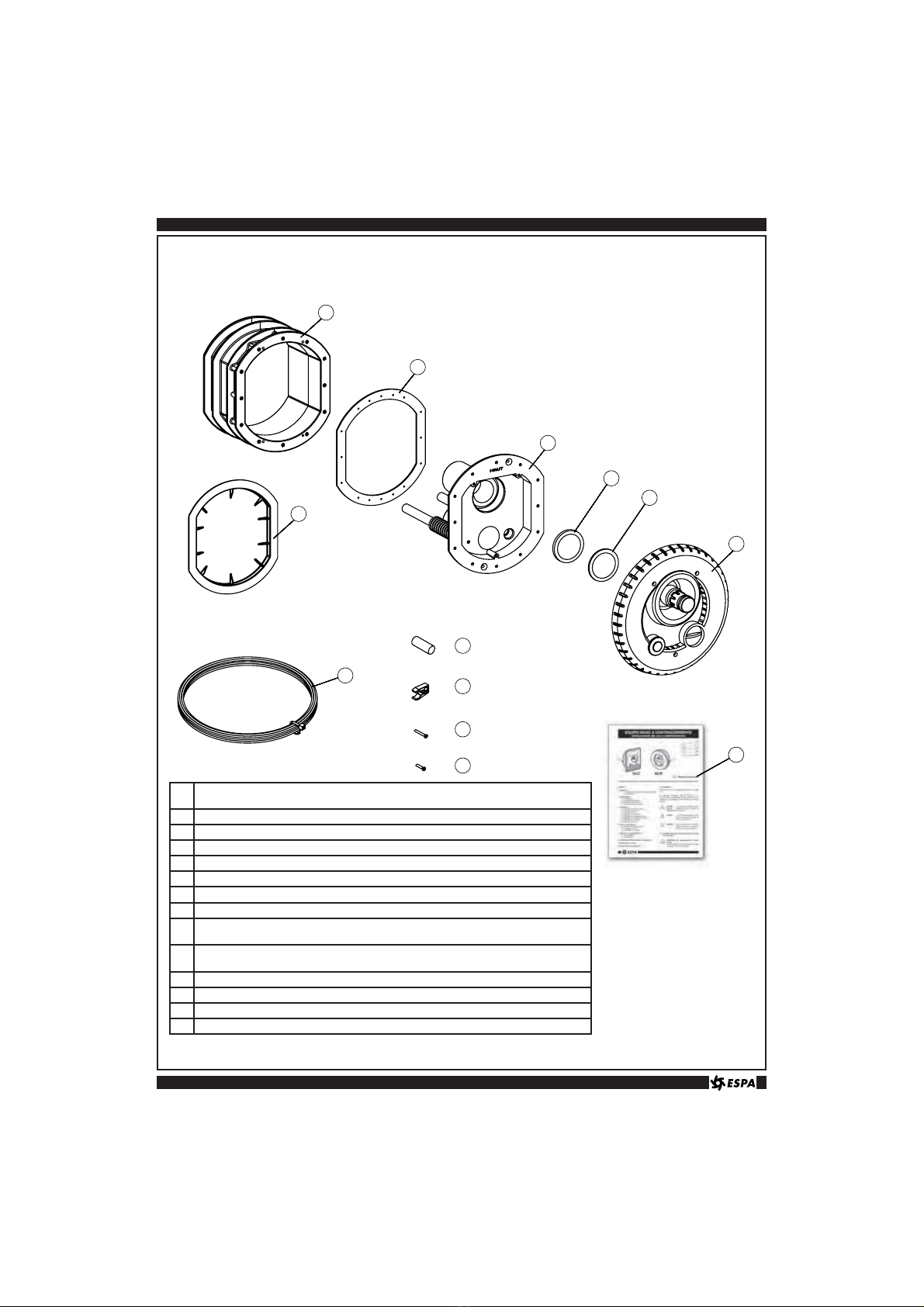
Place the section to be embedded (16) with its
protective plate (17) fixed in the metal mesh which
acts as a framework for the concrete.
Put it in position, bearing in mind that there must
be a distance of approximately 400 mm between
the centre of the section to be embedded and the
maximum height of the swimming-pool.
Position the surfaces of the part in a perpendicular
manner at the base of the swimming-pool.
The surface of the section to be embedded (16),
indicated by the letter S in (Fig. J), must be
aligned with the surface of the concrete once it
has been sprayed, so that the front plate (6) is
well placed once the ceramic wall-tiles have been
fixed in place. (Fig. J)
Once the concrete has been sprayed, remove the
protecting plate (17) and clean the surface of the
embedded section (16).
Attach the foam gasket (2) to the embedded
section (16).
Introduce the front section (3) into the embedded
section (16) and join together with screws (18)
(Fig. K)
Ensure that the rear body (3) is in correct position.
The word “HAUT” must be at the top part. (Fig. E)
Fitting front plate.3.4.
Pass the capillary pipe (7) through the hole in the
rear body (3) until it emerges from the end of the
hose on the side of the connections to the pump.
(Fig. N)
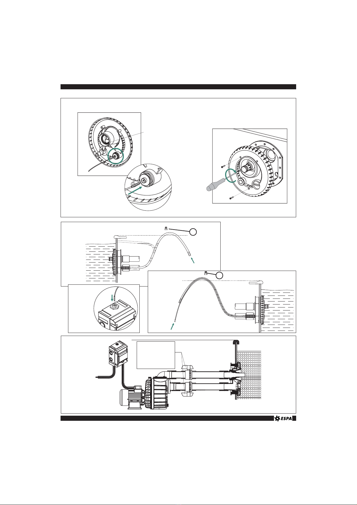
Fit the capillary pipe (7) by pressing it into the
pressure switch and ensuring that it is securely
connected.
Offer the front plate (6) up to the rear body (3),
ensuring that the rubber gasket is in place before
fixing the unit with the 3 M5 screws (12).
For sprayed concrete swimming-pools, place
joints no.(19) and/or (20) as necessary to adjust
the jet of the front plate (6).
Fitting the air hose.3.5.
The hose must be attached to the wall to form an
air trap, or at a level above the maximum height
of the swimming pool, so as to avoid emptying the
pool. Alternatively, it can be attached to the wall at
a height between the waterline and the maximum
height of the pool. Use a securing staple (10) to
ensure correct fitting.
Mount the filter (9) on the end of the hose in order
to prevent dirt entering. (Fig. P)
Fitting the pressure switch.3.6.
The hose must be attached to the wall to form an
air trap, or at a level above the maximum height
of the swimming pool, so as to avoid emptying the
pool. Use a securing staple (10) to ensure correct
fitting.
Cut the hose to the right length to reach the
panel (8) and mount the filter (9) on the end of
the hose in order to prevent dirt entering.
The maximum length to ensure correct operation
of the pressure switch is 25 metres. It is advisable
to cut the capillary pipe to just the right length to
reach the panel (8), ensuring that the connecting
pipe is passed through again. (Fig. Q)
Connect the capillary pipe (7) to the pressure
switch, ensuring that it is firmly connected.
(Fig. R)
Fitting the pump.3.7.
Pump installation and assembly must be carried
out by an authorised installer.
General safety warnings.a)
The equipment must be fitted following
current safety regulations for installing
swimming pools, and particularly standard
IEC 60364-7-702 and the special regulations
for each application.
The pump must be installed on a flat surface
and attached to the floor.
To ensure the safety of persons, the pump
must be installed at least 3.5 metres from the
swimming pool.
The mains electricity supply must be protected
by an automatic power-supply cut-out device,
a residual current circuit-breaker switch (Δ fn)
not exceeding 30 mA.
Fitting the pipes.b) (Fig. S)
The connection pipes to the pump for
distances of up to 3.5 metres must have a
minimum diameter of DN63. For distances of
up to 5 metres from the swimming pool piping
of DN75 must be used, and DN90 piping for
distances of more than 5 metres.
Flow valves must be fitted in the discharge
and suction pipes, so that the pump can be
removed for maintenance without draining the
swimming pool.
Particular care must be paid to ensure that
water cannot enter the pump motor or other
electrically powered parts of the installation.

10
Instruction manual
The premises in which the pump is installed
must comply with the complementary technical
safety instructions applicable to damp or wet
premises.
The premises must be provided with a drain
that allows water to be evacuated in the event
of flooding of the premises that might be
detrimental to electrical safety and cause injury
to persons.
For optimum pump operation and reliability the
premises must be provided with a ventilation
inlet.
The installation pipes and accessories must be
made of PVC. Under no circumstances must
iron pipes or accessories be used, as they
could damage the plastic components of the
installation.
Electrical wiring.c) (Fig. T)
The wiring must be in accordance with EEC
standard or of type H07 RN-F according to
VDE 0250.
The electrical trunking must be watertight,
and connections and their fittings must have a
sufficient degree of protection against vertical
fall of water drops. Connections, trunks and
branch connections must always be housed in
leaktight boxes.
Installation and assembly must be entrusted to
an authorised installer.
Start-up.3.8.
Once the connections have been made and before
running the pump the leaktightness of joints must
be checked. Switch on the water supply to the pump
and eliminate any air left inside the pump by using
the bleed devices on the pump.
Start up the pump. Press “Start” on the electrical
panel (8) and press the pneumatic pump-start
button.
The pipe valves must be fully open during
pump operation and must never be closed
while it is running. Shutting off or quickly
reducing the passage of water can give rise to
pressure surges that could lead to equipment
breakage.
Leave the pump running for a few minutes and
check that the equipment has been correctly
installed.
INSTRUCTIONS FOR USE.4.
Starting / Stopping the pump.4.1. (Fig. U)
The pump will come into operation when the
pneumatic pushbutton is pressed, and will stop if it
is pressed again.
Air regulator.4.2. (Fig. V)
With the hydromassage hose connected, turn the
regulating button to regulate the air bubbles.
Keep air passage closed if the massage
hose is not in use.
Note: The hydromassage hose is
an accessory not supplied with the
equipment.
Flow regulator.4.3. (Fig. W)
The water flow can be adjusted by turning the
discharge pipe to the right or to the left.
The direction of the water jet can also be adjusted
using the discharge pipe knuckle-joint system.
REPAIR AND MAINTENANCE.5.
General considerations.5.1.
Check the air-passage filter (9) and if necessary
clean out any dirt or insects.
Overwintering.5.2.
The installation must be protected in winter
against the potential risk of freezing. The following
operations will have to be carried out:
– Disconnect the pump from the electricity supply.
– Remove the front plate (6) and the capillary
pipe (7) of the pressure switch and stow them
away.
– Drain the water from inside the pump, using the
drain plug. (Fig. N)
– Fit the protective cover (4).
After the overwintering period refit the components
removed and, before running the pump:
– Check manually to ensure that the pump motor
shaft rotates, by rotating the fan.
– Check the connections for leaktightness.
Correct operation of the installation must be
checked during the first few minutes of running.

11
POSSIBLE PROBLEMS, CAUSES AND SOLUTIONS.6.
PROBLEMS CAUSES SOLUTIONS
– Water flow is
insufficient
– Recirculation of water.
– Maximum flow of the pump is
small.
– Comprobar el correcto montaje de los componentes
y en especial la presencia de la junta.
– Comprobar el correcto dimensionamiento de la
bomba.
– No air bubbles
emerge
– The filter (9) fitted in the hose is
dirty and air does not pass.
– Air passage at the front plate (6)
is obstructed by insects or foreign
bodies.
– The air regulator is closed.
– Clean the filter (9) and remove impurities.
– Clean and ensure that air is passing to the
discharge pipe.
– When the air regulator is opened bubbles should
emerge.
– The pump does
not start
– The capillary pipe (7) is
disconnected or has leaks.
– There is no electricity supply to
the installation.
– Incorrect pressure microswitch
operation.
– Check that the capillary pipe (7) is correctly
installed.
– Wait for electricity supply to be restored.
– Check electrical continuity at the pressure switch by
activating and deactivating the button.
– The pump stops
running
– The pump thermal cut-out switch
activates.
– The motor-protection cut-out on
the panel throws.
– The installation’s differential
circuitbreaker switch triggers.
– Electrical connection failure.
– Check that the premises is correctly ventilated and
that air passage of the pump fan is not obstructed.
– Check that the pump ampere rating is less than or
equal to the cut-out trigger rating.
– Check for insulation or shunt-off faults.
– Check that electrical connections are correct.
– The pump does
not take in
water
– The pump is not primed.
– The suction pipes are not sealed
and the pump takes in air.
– The suction piping is long and the
pump is higher than the swimming
pool level.
– Pool water level insufficient and
air is being taken in.
– Fill the suction body up to the level of the suction
connection.
– Repair leaks.
– Bleed air from the pump.
– A check valve without spring pressure must be
mounted in the suction pipes to prevent water
draining during suction.
– Raise the water level of the pool to at least 10 cm
above the plate.
– The motor
protection
switch triggers
– Condenser defective.
– Pump blocked by obstruction of
the turbine.
– Check that the condenser is of the correct capacity.
– Replace if faulty.
– The motor shaft must rotate slightly.
– If not, the pump must be repaired by the technical
service centre.
– Noise – Air is entering the equipment.
– Noise from bearings.
– Foreign bodies in the pump.
– Stop leaks.
– The pump must be repaired by the technical service
centre.
– Remove them as explained in the pump
maintenance manual.
Instruction manual

32
Fig. 1 Componentes principales para estructura panel o poliéster.
Main components of the panel or polyester structure.
Composants principaux pour structure panneau ou polyester.
Hauptkomponenten für Platten- oder Polyesterstruktur.
Componenti principali per struttura pannello o poliestere.
Hoofdcomponentes voor paneelstructuur of polyester.
PIEZA/MODELO • PART/MODEL • PIÈCE/MODÈLE • TEIL / MODELL • PEZZO / MODELLO • ONDERDEEL /
MODEL
1 Contrabrida fijación / Securgin counterflange / Contrebride fixation / Gegenflasch / Controbrida fissagio /
Tegenflens bevestiging
2 Junta espuma / Foam gasket / Joint mousse / Dichtung / Guarnizione schiuma / Schuimrubberen ring
3 Cuerpo posterior / Rear body / Corps arrière / Rückwärtiger Aufsatz / Corpo posteriore / Achterlichaam
4 Placa protectora / Protective plate / Plaque de protection / Schutzplatte / Targa protetrice / Beschermingsplaat
5 Brida fijación / Securing flange / Bride fixation / Flansch / Brida fissaggio / Bevestigingsflens
6 Placa anterior / Front plate / Facade / Frontplatte / Targa anteriore / Voorplaat
7 Tubo capilar / Capillary tube / Tube capillarire / Kapillarrohr / Tubo capillare / Capilaire buis
9 Filtro espuma / Foam filter / Filtre mousse / Filter / Filtro schiuma / Schuimfilter
10 Grapa sujección / Securing staple / Clip fixation / Halteklammer / Graffa soggezione / Bevestigingsbeugel
11 Tornillo / Screw / Vis / Schraube / Vite / Schroef DIN7982 Ø4.8x45
12 Tornillo / Screw / Vis / Schraube / Vite / Schroef DIN965 M5x30
13 Tornillo / Screw / Vis / Schraube / Vite / Schroef DIN7982 Ø5.5x16
14 Manual de instrucciones / Intruction manual / Manuel d’instructions / Betriebsanleitung / Manuale d’instruzioni /
Instructiehandleiding
15 Dibujo patrón / Template / Gabarit / Schablone / Disegno campione / Mal

33
16
2
3
6
17
9x2
10 x2
18 x12
12 x3
7
14
19
20
Fig. 1 Componentes principales para piscinas de hormigón gunitado.
Main components of sprayed-concrete swimming-pools.
Composants principaux pour piscines en mortier gunit.
Hauptkomponenten für Spritzbeton-Swimmingpools.
Componenti principali per piscine in cemento iniettato.
Hoofdcomponenten voor zwembaden van spuitbeton.
PIEZA/MODELO • PART/MODEL • PIÈCE/MODÈLE • TEIL / MODELL • PEZZO / MODELLO • ONDERDEEL /
MODEL
2 Junta espuma / Foam gasket / Joint mousse / Dichtung / Guarnizione schiuma / Schuimrubberen ring
3 Cuerpo posterior / Rear body / Corps arrière / Rückwärtiger Aufsatz / Corpo posteriore / Achterlichaam
6 Placa anterior / Front plate / Facade / Frontplatte / Targa anteriore / Voorplaat
7 Tubo capilar / Capillary tube / Tube capillarire / Kapillarrohr / Tubo capillare / Capilaire buis
9 Filtro espuma / Foam filter / Filtre mousse / Filter / Filtro schiuma / Schuimfilter
10 Grapa sujección / Securing staple / Clip fixation / Halteklammer / Graffa soggezione / Bevestigingsbeugel
12 Tornillo / Screw / Vis / Schraube / Vite / Schroef DIN965 M5x30
14 Manual de instrucciones / Intruction manual / Manuel d’instructions / Betriebsanleitung / Manuale d’instruzioni /
Instructiehandleiding
16 Cuerpo a empotrar / Section to be embedded / Bloc à encastrer / Einbaugehäuse / Corpo da incassare /
Inbouwlichaam
17 Placa protectora / Protective plate / Plaque de protection / Schutzplatte / Targa protetrice / Beschermingsplaat
18 Tornillo / Screw / Vis / Schraube / Vite / Schroef DIN7985 M5x16
19 Junta grosor / Thick washer / Joint épaisseur / Dichtung Dicke / Giunto spessore / Dikke ring: 2 mm
20 Junta grosor / Thick washer / Joint épaisseur / Dichtung Dicke / Giunto spessore / Dikke ring: 1 mm

34
Fig. A Fig. B Fig. C
Fig. D
A
B
Fig. E
Fig. G Fig. H Fig. I
Fig. J Fig. K Fig. M
Fig. F

35
Fig. N
Fig. P
MANUAL DE INSTRUCCIONE S
Junta de goma
Rubber gasket
Joint en caoutchouc
Gummidichtung
Guarnizione di gomma
Ubberen ring
Válvulas de paso
Flow valves
Vannes d’isolement
Durchgangsventil
Valvole di passagio
Afsluitkleppen
Fig. Q
Fig. R
Fig. S
10
10

36
Fig. T
Fig. U Fig. V Fig. W
Armario maniobra monofásico
Single-phase control cabinet
Coffret commande monophasée
Steuerschrank mit Einphasenstrom
Armadio manovra monofasico
Eénfasige bedieningskast
Armario maniobra trifásico
Three-phase control cabinet
Coffret commande triphasée
Steuerschrank mit Drehstrom
Armadio manovra trifasico
Driefasige bedieningskast
Esquema de conexiones / Wiring diagram / Schéma de branchements /
Schaltbild / Schema de collegamenti / Verbindingschema
Máximo Medio caudal Mínimo
Maximum Medium flow Minimum
Maximum Moyen débit Minumum
Maximal Mittel
Durchflussmenge
Minimal
Massimo Portat media Minimo
Maximaal Half debiet Minimaal

37
Fig. 2 Fig. 3
Parte interior de la piscina
Interior part of the swimming pool
Partie intérieure de la piscine
Inneren Beckenbereich
Parte interna della piscina
Gedeelte binnen het zwembad
Parte interior de la piscina
Interior part of the swimming pool
Partie intérieure de la piscine
Inneren Beckenbereich
Parte interna della piscina
Gedeelte binnen het zwembad
DIMENSIONES Y PESOS / DIMENSIONS AND WEIGHTS / DIMENSIONS ET POIDS /7.
ABMESSUNGEN UND GEWICHTE / DIMENSIONI ET PESI / AFMETINGEN EN GEWICHTEN
MODELO / MODEL
MODÈLE / MODELL
MODELLO / MODEL
A B PESO / WEIGHT / POIDS /
GEWICHT / PESO / GEWICHT
(kg)
Kit NCRL 314 40 4
KIT NCCL 340 40 4
KIT NCRH 314 150 4.6
KIT NCCH 340 150 4.6

38

39

40
CONJUNTOS TÉCNICOS HIDRÁULICOS, S.A.
Polígono industrial UP-4 Puigpalter
17820 BANYOLES
GIRONA - SPAIN
EPRODUCTOS: DPRODUKT:
GB PRODUCTS: IPRODOTTI: KIT NCC / NCR
FPRODUITS: NL PRODUCTEN
BOMBAS ELÉCTRICAS, S.A.
Carretera de Mieres, s/n
17820 Banyoles - España
Tel. +34 972 588 000
Fax +34 972 588 021
DECLARACIÓN DE CONFORMIDAD:
Los productos mencionados en el manual se hallan conformes a:
Directiva 73/23/CEE (Baja tensión). Directiva 89/336/CEE (Compatibilidad electromagnética).
Norma Europea EN 60.335-2-41. Norma Europea EN 55014-1/2
Firma/Cargo: Jordi Planas (Responsable Técnico)
COMPLIANCE DECLARATION
The products mentioned in the manual comply with:
Directive 73/23/EEC (Low Voltage). Directive 89/336/EEC (Electromagnetic Compatibility).
European standard EN 60.335-2-41. European standard EN 55014-1/2.
Signature/Post: Jordi Planas (Technical Director)
DÉCLARATION DE CONFORMITÉ :
Les produits mentionnés dans le manuel sont conformes à :
La Directive 73/23/CEE (Basse tension). La Directive 89/336/CEE (Compatibilité électromagnétique).
La Norme européenne EN 60.335-2-41. La Norme européenne EN 55014-1/2.
Signé/fonction : Jordi Planas (Responsable technique)
KONFORMITÄTSERKLÄRUNG
Die in diesem Handbuch beschriebenen Produkte entsprechen den folgenden Bestimmungen:
Richtlinie 73/23/EWG (Niederspannung). Richtlinie 89/336/EWG (Elektromagnetische Verträglichkeit).
Europäische Norm EN 60.335-2-41. Europäische Norm 55014-1/2.
Unterschrift/Stellung: Jordi Planas (Technischer Leiter)
DECLARAÇÃO DE CONFORMIDADE
Os produtos mencionados no manual estão conformes a:
Directiva 73/23/CEE (Baixa tensão). Directiva 89/336/CEE (Compatibilidade electromagnética).
Norma Europeia EN 60.335-2-41.Norma Europeia EN 55014-1/2.
Firma/Cargo: Jordi Planas (Responsável Técnico)
CONFORMITEITSVERKLARING:
De in deze handleiding vermelde producten voldoen aan:
De laagspanningsrichtlijn 73/23/EEG. EMC-richtlijn 89/336/EEG.
Europese norm EN 60.335-2-41. Europese norm EN 55014-1/2
Handtekening/Functie: Jordi Planas (Technisch directeur)
Distribuidor oficial
Cód. 23000664 04-2009/03
Other manuals for NCC
1
This manual suits for next models
1
Table of contents
Other Espa Water Pump manuals
Popular Water Pump manuals by other brands

Fristam Pumps
Fristam Pumps FL2 Series Idea instruction and maintenance manual

NEXTTEQ
NEXTTEQ NX-1000 instruction manual

IBO
IBO MAGI 25-100/180 Operation manual

Homa
Homa SaniQ cut Original instruction manual

Performance Tool
Performance Tool W89727 owner's manual

Agilent Technologies
Agilent Technologies 1260 Infinity user manual

Oase
Oase Aquamax 4.000 operating instructions

GE
GE Peristaltic Pump P-1 operating instructions

Hirtz
Hirtz HICOVAC 700 CH operating instructions

Pattfield Ergo Tools
Pattfield Ergo Tools E-GP 6036 operating instructions

Pentair
Pentair HYDROMATIC HPUSP125 Installation, operation & parts

Bredel
Bredel APEX 10 Original instructions