3. Precautions
3.1. Essex Electronics keypads & card readers are electronic devices and are sensitive
to electrostatic discharge. Standard precautions should be taken to protect these
devices from electrostatic discharge events.
3.2. Essex Electronics does not manufacture the control panels & power supplies that
may be connected to these keypads & readers. Care should be taken to select
operating characteristics of the external devices before connecting Essex
Electronics manufactured devices. See Essex Electronics warranty policy at;
https://www.keyless.com/wp-content/uploads/2018/11/Warranty.pdf
3.3. Our keypads and readers are only part of an access control system. Essex
Electronics has designed these products to work with most access control systems
& power supplies. The installer is cautioned to avoid operating these devices
outside of the recommended specifications.
3.4. The supplied keypad, the K1-34, is a multi-format keypad that is by default in the
26 bit format. If another format is required see the following paragraphs, and the
supplied instruction sheet for the Multi-Format. The wiring harness & hardware
kit that comes with the keypad is not required for installation on to the reader.
The wiring harness that comes with the reader is used in place of this harness &
hardware kit.
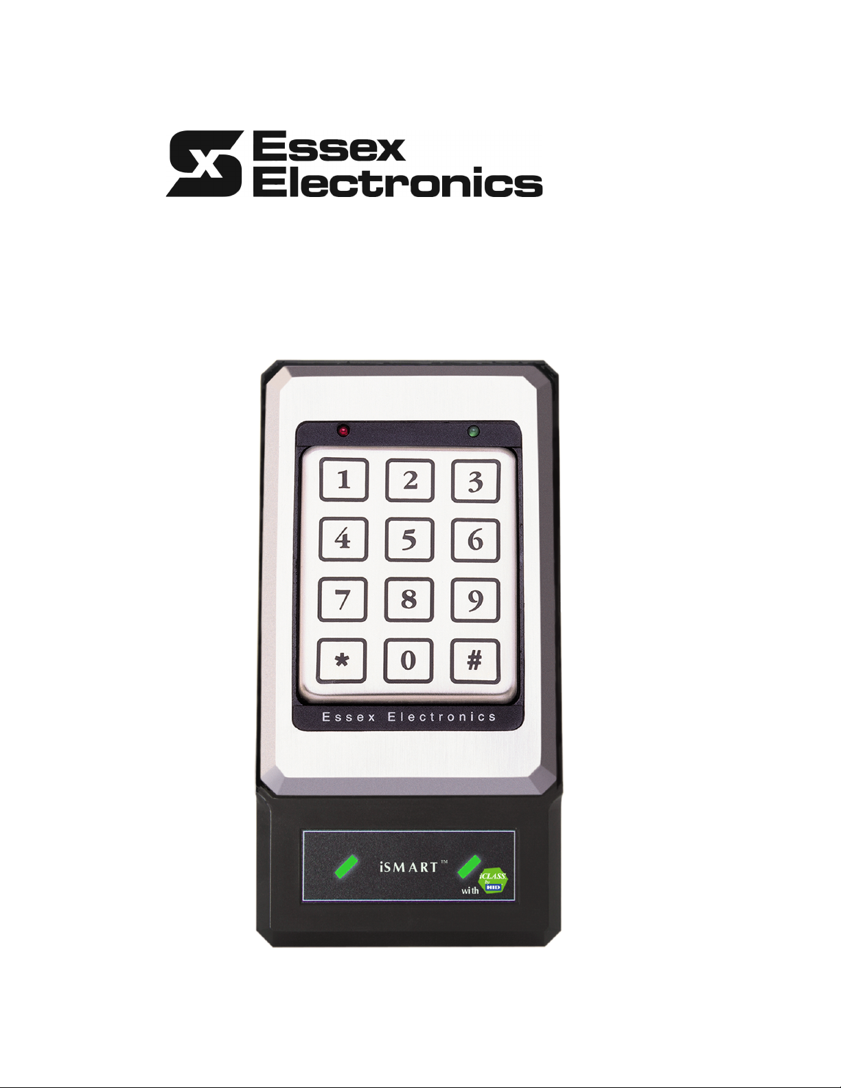
4. Settings
4.1. Select the style of keypad required. Default output of the K1 Series Keypad is 26
bit Wiegand.
4.1.1. For two factor authentication of so called “pin and code”, set the keypad to the 8-
bit Wiegand output;
4.1.2. Remove power from the keypad.
4.1.3. On the keypad, jumper the two pins above the connector labeled “CONFIG”.
4.1.4. Apply appropriate power, (you should hear four beeps and the red LED will flash,
and the green LED will be solid.
4.1.5. Select the 8-bit Wiegand mode by entering “2” & then “#”.
4.1.6. The keypad will respond with three beeps, indicating successful configuration. If
you hear a long error beep, re-enter the configuration “2” & then “#”.
4.1.7. Remove power.