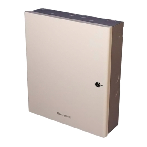
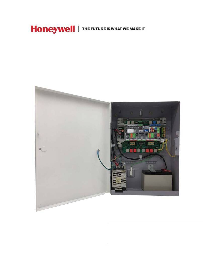
Honeywell ACS-8 User manual

P32501-02-0G0-16 Z 105009 Software-Version
ZACS8.00.0V0.11.xx
Subject to change
without notice
2017-07-20
Installation Instructions
ACS-8
Item no. 026575, 026580, 026585

.
VdS Approval
Z 105009, class C

Installation Instructions / ACS-8 3
Contents
1. Safety instructions ................................................................. 7
1.1 Installation and expansion ...................................................... 7
1.2 Symbols ................................................................... 8
1.3 Firmware update ............................................................ 8
2. Overview ......................................................................... 9
2.1 Device ..................................................................... 9
2.2 Bus ...................................................................... 10
3. General information ............................................................... 11
4. Protective measures .............................................................. 12
5. Important installation instructions ................................................... 13
5.1 Grounding / shielding ........................................................ 13
5.2 Shielded lines .............................................................. 14
5.2.1 Illustrationoftheshielding .............................................. 14
5.2.1.1 General shielding principle ....................................... 14
5.2.1.2 ShieldingoftheACS-8-systems ................................... 15
6. ACS-8 / Cables ................................................................... 17
6.1 ACS-8 supply voltages ....................................................... 17
6.1.1 230 V-version of the ACS-8 ............................................. 17
6.1.2 12V-versionoftheACS-8 .............................................. 17
6.2 ACS-8 module-bus / cables ................................................... 19
6.2.1 Cabletypesfordatalines............................................... 19
6.2.2 Cable types for the power supply of bus modules ............................ 19
6.2.3 ACS-8 module-bus .................................................... 19
6.2.3.1 Power supply .................................................. 19
6.2.3.2 Power supply of the modules via the bus line ......................... 19
6.2.3.3 Power supply of the modules via a separate supply unit ................ 20
6.2.3.4 Cable lengths and cross section .................................. 20
6.3 Linestubs ................................................................. 20
6.4 Potential separation ......................................................... 20
6.4.1 Central power supply by the ACS-8 ....................................... 20
6.4.2 Decentralized power supply using several external supply units distributed
inthesystem ........................................................ 20
6.5 Shielding /grounding of the module bus .......................................... 21
6.6 Calculationexamples ........................................................ 21
6.6.1 Calculation of the line cross-section with given length ......................... 21
6.6.2 Calculation of the maximum cable length with given line cross-section ............ 25
7. Interface and bus topology ......................................................... 37
7.1 Interface technology, RS 485-bus systems ........................................ 37
7.1.1 Principle ............................................................ 37
7.1.2 General information ................................................... 37
7.1.3 Potential separation and terminating resistance ............................. 38
7.1.4 Ethernet connection (RJ 45) ............................................ 39
7.2 Connection examples and networks ............................................. 39
7.3 Interface connections ........................................................ 41
7.4 Pinassignmenttables ........................................................ 42
7.5 Connection examples ........................................................ 43

4Installation Instructions / ACS-8
8. Configuration .................................................................... 44
8.1 Conventional connection ..................................................... 44
8.2 Connection via the optional communication module ................................ 45
8.2.1 Overview ........................................................... 45
8.3 Configuration examples peripheral devices ....................................... 46
9. Mounting ....................................................................... 51
9.1 Locationofinstallation ....................................................... 51
9.2 Mounting the ACS-8 ........................................................ 51
9.3 Installingtheinterface ....................................................... 52
9.4 Installing the communication module ............................................ 53
9.4.1 Information about the communication module .............................. 55
9.5 Inserting / changing the lithium battery ........................................... 57
9.6. DIP-Schalter on the CPU board ................................................ 60
9.6.1 DIP-switchS1 ....................................................... 60
9.6.2 DIP-switchS2 ....................................................... 62
9.6.3 DIP-switchS3 ....................................................... 62
9.6.4 DIP-switchS4 ....................................................... 63
9.7. Memory expansion .......................................................... 64
9.7.1 Calculation of the memory requirements ................................... 64
9.7.2 Inserting / changing the memory card ..................................... 69
10. Sizing of the power supply unit and the battery ........................................ 70
10.1 Sizing of the power supply unit ................................................. 70
10.2 Sizingofthebattery ......................................................... 71
10.3 Power supply / charging unit, 12V DC / 40 Ah, item no. 010690.02 .................... 72
11. Comissioning .................................................................... 77
11.1 ACS-8-Setup .............................................................. 77
11.2 DefiningthecontrollerinNetEdit ............................................... 86
12. LEDs, buzzer and cancel buzzer push-button ......................................... 87
13. Outputs ......................................................................... 88
13.1 Semiconductor outputs ....................................................... 88
13.2 Relayoutputs .............................................................. 88
14. Inputs .......................................................................... 90
14.1 Digital Inputs .............................................................. 90
14.2 Monitored inputs ............................................................ 90
15. Structure / diagrams .............................................................. 91
15.1 CPU component mounting diagram ............................................. 91
15.2 ACS-8structure ............................................................ 93

Installation Instructions / ACS-8 5
16. Connections ..................................................................... 94
16.1 Assignment ................................................................ 94
16.2 General connection diagram ................................................... 95
16.3 Pin assignment of the host interface connections ................................... 95
16.4 Connecting a door strike ...................................................... 96
16.4.1 Connecting a fail secure door strike ....................................... 96
16.4.2 Connecting a fail safe door strike ......................................... 97
16.5 Electricsafetylock .......................................................... 97
16.6 Turnstile ................................................................. 100
16.6.1 Turnstile with one monitoring contact ..................................... 100
16.6.2 Turnstilewithtwocommonmonitoringcontacts ............................ 101
16.6.3 Turnstile with two separate monitoring contacts ............................ 103
17. Connection diagrams ............................................................. 104
18. Connections / Technical data ...................................................... 127
18.1 Connections 026580, ACS-8 12V-version ....................................... 127
18.2 Connections 026585, ACS-8 230V-version ...................................... 127
18.3 Connections 026575, ACS-8 230V-version ...................................... 127
18.4 Technical data 026580, ACS-8 12V-version ...................................... 128
18.5 Technical data 026585, ACS-8 230V-version ..................................... 128

6Installation Instructions / ACS-8
Appendix
1. Master sheet for terminal assignment, empty ........................................ 130
2. Master sheet for the calculation of the memory requirements, empty .................... 131
3. Planning examples .............................................................. 132
4. Factory settings ................................................................. 138
5. Index .......................................................................... 139

Installation Instructions / ACS-8 7
1. Safety instructions
Danger for device or user if ignoring the following safety instructions!
* Please read this manual carefully and completely before working with the ACS-8.
* Only use the ACS-8
- for the purpose it is designed for
- when there is no obvious damage to the unit
- when it is installed as per the manufacturers recommendations
- referring to the technical data supplied
* The manufacturer cannot be held liable for damage resulting from use contrary to the designated purpose.
* Store the documents accompanying the product and product-specific notes in a safe place.
* Mounting, programming, maintenance and repair work must be carried out only by authorized and trained
personnel.
* Soldering and connecting work on any part of the system may only be carried out when the system is
isolated from the power supply.
* Soldering work must only be performed with a temperature regulated soldering iron galvanically separated
from the power supply.
* The VDE safety regulations and the prescriptions of the local electricity supplier must be observed.
*Danger: The ACS-8 must not be used in any environment where there is a risk of explosion or in
areas with caustic or solvent atmospheres
1.1 Installation and expansion
Warning: Switch off the supply voltage before opening the device.
The VDE regulations and those of the electricity supplier must be observed during installation. Ensure that
connections between the control unit and the external devices are in accordance with the connection
diagrams.
An isolating circuit breaker must be integral to the supply of the building.
Use only shielded cables (see chapter 5 (Important installation instructions) and chapter 6 (ACS-8/cables)).
When using a DC door strike, ensure correct polarity at all times. Only use DC door strikes equipped with
a protective diode.

8Installation Instructions / ACS-8
1.2 Symbols
The following symbols are used in this manual:
Warning!
Instructions or information with vital importance for the safety of personnel or equipment.
Information relative or peripheral to the current topic.
Information on the current topic with important or far-reaching consequences.
Information on mounting and installing.
1.3 Firmware update
The firmware update can be done by a flash update via the superior software (e. g. IQ MultiAccess). The
procedure is described in the corresonding software manual. In general we recommend to update always
to the latest available version in order to use all features - including new options. The current firmware can
be found on the installation CD of IQ MultiAccess, it will be automatically copied into the firmware download
directory of the IQ MultiAccess computer (server) during the installation routine or can be downloaded for
free from our homepage.

Installation Instructions / ACS-8 9
2. Overview
2.1 Device
Functon (in alphabetical order) to set up via page
Address S1 or ºSetup 61
Battery 71
Baud rate S1 or ºSetup 62
Clock/Data S2 63
Communication module S1 of communication module 54-57
Flashbank S3 63
Interface card BU 4 / BU 5 53
Memory expansion BU 2 65
Power supply unit 71
Protocol S1 or ºSetup 62ff
RS 485 ºCommunication module / Terminating resistors
Service S1 62
Setup S1 62f
Terminating resistors ST 102/103, ST 202/203 54

10 Installation Instructions / ACS-8
2.2 Bus
Furtheron the following terminology is used:
Device bus: RS 485 connection of the access control central units (e. g. ACS-8) to host.
Module bus: RS 485 connection of ACS-8 (via communication module, see chapter 8.2 and 9.4) to the
bus modules controlled by the ACS-8.
Modules possible: Input module
Output module
Input- / output module
Potential separator module
Door module
Bus reader (reader in RS 485 mode)
Trafficpoint RS-485 for DLC and DLF
Clock/Data: Readers/keypads in clock/data mode connected directly onboard to the ACS-8.
Connection diagrams see chapter 17.

Installation Instructions / ACS-8 11
3. General information
Access control systems are used where access to restricted areas is limited to authorised personnel.
Software
On the systems described here, MultiAccess for Windows or IQ MultiAccess is the governing software for
all access control devices. Access rights for personnel, actions, time orders and the transmission of the data
to the hardware can all be set up using this software.
Hardware
The ACS-Compact, ACS-1, ACS-2 and ACS-8 are the controllers that control access and together are
responsible for the overall operational functionality. After receiving their data from MultiAccess for Windows
or IQ MultiAccess, the controllers can operate in stand-alone mode. This means that the control of access
remains active without impairment even if MultiAccess for Windows or IQ MultiAccess is not running.
When starting MultiAccess for Windows or IQ Multi Access, the events that have occurred while the PC was
offline are automatically entered into the event log file.
The display panel is a device used for the indication of door states, actions and the whereabouts of
personnel.
The ethernet interface (LAN) links between the PC and the controllers and is also responsible for
antipassback control. The PC configured with IQ MultiAccess must be in operation.
When ACS-8 systems are used in simplified mode the interface converter 026817.03 can be used.
If only one ACS-8 is connected it can be directly connected using the RS 232 serial interface.
These connections can be made in various permutations.

12 Installation Instructions / ACS-8
4. Protective measures
Defence against electrostatic discharge
Modern semiconductor devices are susceptible to electrostatic charges. The higher the integration density,
the finer the structures on the chip and the greater the danger of electrostatic damage.
With some semiconductor devices, damage may be caused by less than 20V. This is a very low value when
values of greater than 1000v can be generated by walking across a carpet.
Damage caused by electrostatic discharge rarely leads to instant failure. More commonly, semiconductor
structures receiving damage from electrostatic discharges have a residual burning trace which initiates a
chemical process on the chip, causing it to degrade over a period of days, weeks, months or even years.
Partial operation can be difficult to detect until eventual failure occurs.
Protection against electrostatic charge
As electrostatic charges cannot be avoided, the electronics must be protected from dangerous voltage
levels.
- Wear an ESD wriststrap connected to the earth connection of the controller.
- Use only soldering irons that are galvanically separated from the power supply and equipped with
an electronic temperature control.
Protective measures against over-voltage transients
Protective shielding and grounding must be provided to avoid malfunctions and damage to system
components due to over-voltage. This may occur due to switching of supplies or heavy machinery on the
supply line or from direct or indirect effects of thunderstorms. (See DIN VDE 0845 part 1, Protection of
telecommunication systems against lightning strokes, static charges and over-voltages caused by power
installations – measures against over-voltages.)
Protection according to the VdS requirements is built into the products.
Protection against damage caused by lighting strokes and over-voltages can be assured by implementing
appropriate measures for internal and external lightning (medium and coarse) protection. Additional
requirements will depend on the installation location and the nature of other equipment connected to the
system.
Over-voltage caused by switching actions causes a very steep rate of change of voltage. This means that
the voltage can reach values of several kV within a few microseconds. Such voltage pulses (transients)
cause the destruction of electronic components.
Adequate over-voltage protection, will absorb these transients.
Causes of transient interference voltages
Transient voltages are often caused by atmospheric discharge, i.e. lightning stroke. A lightning discharge
may release currents reaching values over100kA with very short rise times. This current causes a high
voltage drop in the earth resistance of a building and the high rate of change of current induces high
voltages in conductive loops. The energy resulting causes the damage to unprotected devices.
Switching actions in electrical systems also cause over-voltage transients.
High-voltage power supply networks are fitted with high-frequency compensation systems and are coupled
to low-voltage parts of the network. Over-voltages and high-frequency power transients in low-voltage
installations can also be caused by sharp drops in voltage, phase control, etc. In these instances, the rate
of change of current can reach higher values than a lightning stroke.

Installation Instructions / ACS-8 13
5. Important installation instructions
(See also chapter = Safety instructions)
5.1 Grounding and shielding
Use shielded cables and a suitable shielding connection for protection against electromagnetic interference.
Make sure that the line shields in the distribution boxes are connected so that there are no links to other
potentials. In the ACS-8, all shields should be connected to one point using the shortest possible route.
The shield soldering bar serves as a common point for connection of the ground conductors and line shields
(see below).
Circuit diagram DB1 and DB2 grounding bridges:
The grounding bridges are located on the CPU board near the power supply unit connector (see chapter
15.1).
The following shielding connections can be made:
Connect the shield soldering bar to the ground conductor and keep the grounding bridges closed
With this method, the DB1 and DB2 grounding bridges provide a capacitive coupling between the ground
conductor and the system operating voltage.
This connection offers excellent protection against conducted interference and cable shield discharges.
However, this connection must only be used if PE and N are connected separately (modern grounding) and
if it is guaranteed that the ground conductor does not carry any high or low frequency signals.
Connect the shield soldering bar to the ground conductor and open the grounding bridges
In this configuration, the capacitive coupling to the system operating voltage is interrupted by the removing
the grounding bridges. This connection should be used if the ground is susceptible to interference, where
the capacitive coupling would transfer it to the ACS-8.
Connect the shield soldering bar to the incoming mains terminal
With this configuration, the shield soldering bar ust
be connected directly to the incoming mains
terminal. This method is used where the ground
conductor is heavily loaded and is the only way to
overcome interference, if there is a problem with
the previous methods described.
See: þVDE 0800 part 2 edition July 1980
þVDE 0800 part 2 AI draft
November 1982

14 Installation Instructions / ACS-8
5.2 Shielded lines
The ACS-8 devices are daisy-chained together using shielded cables.
Use Cat 5 cables or higher.
The shielding of the incoming line connects to the shield terminal bar of the ACS-8. The shielding of the
outgoing line must not be connected.
The shield terminal bar in each ACS-8 must be connected to a separate PE.
(min. cable cross-section 1,5mm²)
When it is not possible to provide a mains earth connection at each device on a 12V system, then a three
core cable should be used to provide the 12V DC power and an earth continuity conductor.
The shielding of the reader line is connected on one side to the shield terminal bar in the ACS-8.
The above points also apply to the ACS-8 module bus.
5.2.1 Illustration of the shielding
5.2.1.1 General shielding principle:

Installation Instructions / ACS-8 15
5.2.1.2 Shielding of the ACS-8 systems
The following illustrations show the wiring (grounding) of an ACS-8 system in schematic form:

16 Installation Instructions / ACS-8

Installation Instructions / ACS-8 17
6. ACS-8/cables
6.1 ACS-8 supply voltage
Please observe the informations about grounding and shielding in chapter 5.
6.1.1 ACS-8 230 V version
Parameter Value
operating voltage range 230 V AC –15% +10%
mains frequency 40 – 60 Hz
power supply cable type NYM 3 x 1,5 mm²
6.1.2 ACS-8 12V version
Parameter Value
operating voltage range 10.0V to 15.0V DC
current consumption depends on the reader type, the number of readers and the interface type
The door strike must be taken into consideration if its supply comes from the ACS-8. The current
consumption of a door strike depends on the type, but lies somewhere between 200mA and 500mA.
The current consumption of an energized door strike must be known for each ACS-8 when
designing a 12 V system.
The following drawing (powered on) shows the voltage drop of a 1.5mm2cable compared to a 4mm2cable.
A power consumption of 1A is calculated for each ACS-8.
Observe the outgoing and return line.

18 Installation Instructions / ACS-8
The voltage diagrams 1 and 2 compare the effects of two cable cross-sections.
The required line cross-section must be calculated using the graphs shown above .
Note! Pay attention to legal rulings!
The local requirements must be observed for the line cross-section. VDE 0100 applies to Germany.
The output fuse of the power supply unit must have the appropriate current rating. The highest
current rating is determined by the smallest line cross-section of the supply cable.

Installation Instructions / ACS-8 19
6.2 ACS-8 module bus/cables
6.2.1 Cable types for data lines
Type Length Comments
J-Y(St)Y up to 40m This cable is available with diameters of 0.6mm
and 0.8mm and various numbers of cores.
Cat-5e (or better) Up to 1200m
6.2.2 Cable types for the power supply of bus modules
-J-Y(St)Y i0.6mm, i0.8mm, depending on the calculation (see appendix/Planning
examples)
Note: The required number of wires must not be greater than the terminal diameter.
When using a single J-Y(St)Y cable to carry both the power supply of the
bus modules and the data signals, the cable length is limited to 40m since
this is the data line limit (see 6.2.1 J-Y(St)Y as data line). This must be the
case even if a longer distance was calculated for the power supply.
-NYM 5 x 1.5mm² (See appendix/Planning examples)
6.2.3 ACS-8 module bus
6.2.3.1 Power supply
There are two possible connection versions:
1. Central power supply of the ACS-8 (in the bus line or a separate line).
- All modules have their voltage supplied by the ACS-8.
- No potential separation is required.
- The maximum distance depends on the voltage drop in the cable.
2. Decentralized power supply by one or more external power supply units distributed throughout the
system.
- All modules connected to an RS 485 module bus must have potential isolators fitted.
6.2.3.2 Power supply of the modules via the bus line
The calculations of the line cross-sections for +12V DC and 0V must take the current requirements of the
connected modules into consideration. In addition, any occasional "switching current" (e.g. relay) must also
be considered.
Even in case of emergency power operation, the operating voltage must not fall below 10V DC. This means
that where the battery voltage is 10.5V DC, only a 0.5V voltage drop can be permitted.
For devices with a power supply of 12V, (without emergency power supply) a voltage drop of 2V can be
permitted.

20 Installation Instructions / ACS-8
6.2.3.3 Power supply of the modules via a separate power supply unit
Since the power supply through a bus is very limited, a separate power supply unit located near the modules
(door) must be used where larger distances or increased current consumption is required.
Each communication module has two RS 485 drivers with a separate supply.
An internal or external power supply can be used for each RS 485 driver. The supplies of the two drivers
must not be inter-connected.
External power supply units supply the potential separation module (POT) with 12V DC. Details of these can
be found in the product list.
6.2.3.4 Cable lengths and line cross-section
A maximum length of 1200m is possible for the RS 485 bus (without power supply).
Whether the +12V/0V lines are included in the bus or on a separate cable, the required cable cross-section
must be calculated.
Modules with higher current demands, require a separate line or a cable with a larger cross-section.
6.3 Line stubs (Blind spurs)
Stubs are not appropriate for use with buses and lead to data reflections (the signals bounce back) from high
impedance blind end terminations and should be avoided during installation.
If stubs cannot be avoided, they must not be greater than 3m in length and the terminating
resistor should not be connected.
6.4 Potential Isolation
The communication module has two floating RS 485 interfaces.
The 4I, 4O, 4I/2O modules are each fitted with a floating RS 485 interface.
The reader, keypad and door modules are not floating.
If potential isolation is required, up to 4 of these modules can be connected to the RS 485 bus with the
potential isolator. Each of the 4 modules can be located up to 10m from the potential isolator (POT).
6.4.1 Central power supply from the ACS-8
No potential isolation is required.
6.4.2 Decentralized power supply using several external power supply units distributed
in the system
If problems should appear with the data transmission to the ACS-8, a potential isolator (POT) should be
used.
Table of contents
Other Honeywell IP Access Controllers manuals

Honeywell
Honeywell VISTA CA-FP-100F User manual

Honeywell
Honeywell MPA2 Troubleshooting guide

Honeywell
Honeywell MPA2C3 User manual

Honeywell
Honeywell IDENT-KEY 3 Instruction manual

Honeywell
Honeywell NetAXS-123 User manual

Honeywell
Honeywell Tema-Voyager Compact User manual

Honeywell
Honeywell MPA1C1 User manual

Honeywell
Honeywell PRO22IC User manual

Honeywell
Honeywell MPA1 User manual

Honeywell
Honeywell NetAXS-123 User manual