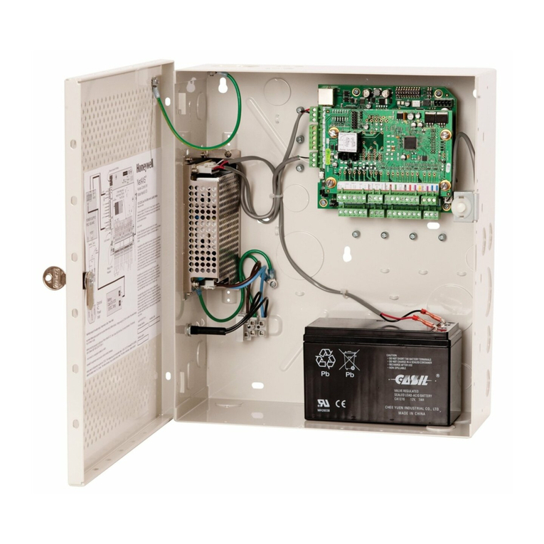
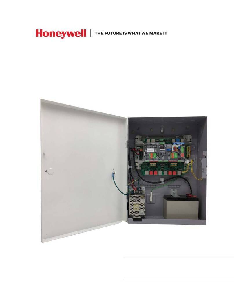
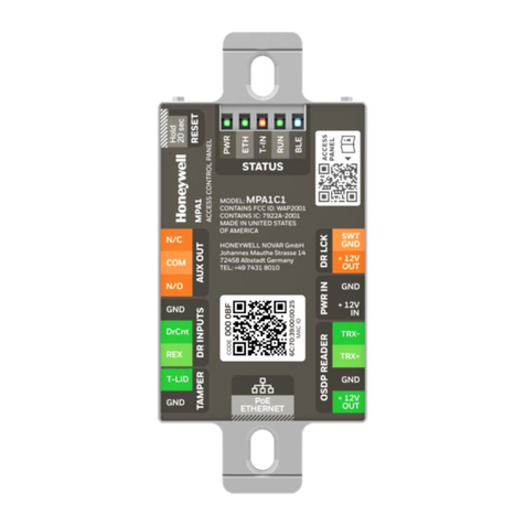
Honeywell MPA2 User manual

December 2019 © 2019 Honeywell. All rights reserved. 800-25395 - B
MPA2
Access Control Unit
Installation Guide
Release 1.0

Copyright © 2019 Honeywell. All rights reserved.
All product and brand names are the service marks, trademarks, registered
trademarks, or registered service marks of their respective owners. Printed
in the United States of America. Honeywell reserves the right to change any
information in this document at any time without prior notice.
Ordering Information
Please contact your local Honeywell representative or visit us on the web at
www.honeywellaccess.com for information about ordering.
Feedback
Honeywell appreciates your comments about this manual. Please visit us
on the web at www.honeywellaccess.com to post your comments.
All information in this document (descriptions, technical specifications, pictures,
illustrations etc) are indicative only, not binding and can be changed without notice.
Nevertheless, this document remains valid.
Personal Data Storage
Please be aware that this product can store personal data. Personal data is
protected by the General Data Protection Regulation (2016/679) in Europe and
therefore the owners of personal data have obtained certain rights thanks to this
regulation.
We strongly advise you to be fully aware of these owner ("data subjects") rights as
well as which limitations you have to obey regarding the use and distribution of
this data. Further details can be found on the GDPR website of the EU:
https://ec.europa.eu/commission/priorities/justice-and-fundamental-rights/dat
a-protection/2018-reform-eu-data-protection-rules_en

Installing the MPA2 Panels
MPA2 Access Control Unit Installation Guide, Document 800-25395 - B 1
Installing the MPA2 Panels
In this manual...
Introduction 2
Panel Components and Descriptions 3
Installation 12
System Configuration 46
Hardware Specifications 54
Firmware Specification 59
Basic Standalone Operation 60
Maintenance 61
Troubleshooting 62
Technical Support 63

2 www.honeywell.com
Installing the MPA2 Panels
Introduction
1.0 Introduction
This document describes how to install the MPA2 Standard Enclosure
access control unit.
Note: All pictures shown in this manual are for illustration purpose only.
Actual product may vary due to product enhancement.
1.1 Access Control Overview
An access control system protects and preserves an enterprise’s resources
by providing authentication, authorization, and administration services.
Authentication is a process that verifies a user’s identity. If the user is
verified, the system then either grants or denies access to specific areas
and resources. Administration includes the creation and modification of
user accounts and access privileges.
An access control system consists of hardware and software, usually
configured in a network environment over a standard network protocol.
Access control units, readers, door strikes, and video and other devices, for
example, are configured to control and monitor the access to a company
site.
1.2 MPA2 Overview
A MPA2 access control is a full-featured two-door web-based access
control system. The MPA2 panel includes a built-in web server, built-in
Ethernet and USB support, and Power over Ethernet (PoE) capability. You
can manage the access control system using either the built-in web
browser, MAXPRO® Cloud (MPC) or WIN-PAK. For supported
configurations, see “System Configuration“ on page 46 to view illustrations
of the supported MPA2 system configurations.
Notes:
• The MPA2 web server/browser is intended for monitoring and
programming use only.
• MPC and WIN-PAK software are intended for monitoring and
programming use only, and have not been evaluated by UL.
• MPA2 system is ULC-Listed for Class I installations.
1.3 Compliance Note
This Class B digital apparatus complies with Canadian ICES-003/ULC 319.
Notes:This equipment has been tested and found to comply with the limits
for Class B and Class A digital device, pursuant to part 15 of the FCC Rules.
These limits are designed to provide reasonable protection against harmful
interference when the equipment is operated in a commercial
environment.This equipment generates, uses, and can radiate radio

Installing the MPA2 Panels
Panel Components and Descriptions
MPA2 Access Control Unit Installation Guide, Document 800-25395 - B 3
frequency energy and, if not installed and used in accordance with the
installation and user guides, may cause harmful interference to radio
communications. Operation of this equipment in a residential area is likely
to cause harmful interference in which case the user will be required to
correct the interference at his own expense.
This Class A digital apparatus complies with Canadian ICES-003.
To obtain applicable EU compliance Declaration of Conformities for this
product,
please refer to our website,
http://www.security.honeywell.com/hsce/international/index.html.
For any additional information regarding the compliance of this product to
any
EU-specific requirements, please contact:
Honeywell Security & Communications
Honeywell Security - Quality Assurance Dept., Newhouse Industrial Estate
Motherwell
Lanarkshire ML1 5SB
Scotland
United Kingdom
Tel: +44(0) 1698 738200
Email: UK64Sales@Honeywell.com
2.0 Panel Components and Descriptions
Note: This device complies with part 15 of the FCC Rules. Operation is
subject to the following two conditions: (1) This device may not cause
harmful interference, and (2) this device must accept any interference
received, including interference that may cause undesired operation.
The MPA2 panel consists of a web-browser-enabled controller, a
power-over-Ethernet (PoE) power supply, and a battery (MPA2 Standard
only).
The following figures show the MPA2 panel wiring and components.

4 www.honeywell.com
Installing the MPA2 Panels
Panel Components and Descriptions
Figure 1: MPA2 Compact Enclosure Wiring and Components

Installing the MPA2 Panels
Panel Components and Descriptions
MPA2 Access Control Unit Installation Guide, Document 800-25395 - B 5
Figure 2: MPA2 Standard Enclosure Panel Wiring and Components
Note: Maintain at least a 0.25-inch (0.65 cm) distance between the
non-power limited wiring (110/220 VAC/50-60 Hz input wiring, power line
filter wiring, and battery backup/charger wiring) and all other wiring, which
is power-limited Class 2 wiring.
2.1 Ferrites
All EMC/CE/FCC compliancy testing was executed using in this manual
specified CAT7 F/STP cable.
Emission compliancy tests have been executed using a ferrite on following
RJ45/USB connections (when used):
J4 = Main Ethernet; USB2 = Host; J16 = Interface Bus; J17 & J18 =
Downstream Bus.
See below the ferrite specification:

6 www.honeywell.com
Installing the MPA2 Panels
Panel Components and Descriptions

Installing the MPA2 Panels
Panel Components and Descriptions
MPA2 Access Control Unit Installation Guide, Document 800-25395 - B 7
The used ferrite has a high impedance (>= 200) in the range of 50 to 250
Mhz. Make sure similar ferrite characteristics is used in your installation for
CE emission compliancy.
2.2 Supervised and Non-Supervised Input Wiring
The supervised inputs are located on the following terminal blocks:
Table 1 Supervised Input Terminal Blocks/RJ45
Table 2 Non- Supervised Input Terminal Blocks/RJ45
Door Status (Drcnt) and Request to Exit (REX) for all doors may be
configured for Normally Open or Normally Closed contacts as supervised
or non-supervised. All inputs on the Controller Board and eight additional
inputs have default functions, but they can be configured for general
purpose inputs.
Board Configuration Terminal Block RJ45
Main Board Rdr/Door1
connector
P10 (GND, DoorCnt1)
P10 (GND, DoorCnt Aux1)
J12 (pin1,3)
J13 (pin1,3)
Main Board Rdr/Door2
connector
P18 (GND, DoorCnt1)
P18 (GND, DoorCnt Aux1)
J14 (pin1,3)
J15 (pin1,3)
Main Board
Additional Input
connector
P24 (GND, InputX (X=1-8))
Board Configuration Terminal Block RJ45
Main Board Rdr/Door1
connector
P10 (GND, REX1)
P10 (GND, REX Aux1)
J12 (pin2,3)
J13 (pin2,3)
Main Board Rdr/Door2
connector
P18 (GND, REX2)
P18 (GND, REX Aux2)
J14 (pin2,3)
J15 (pin2,3)

8 www.honeywell.com
Installing the MPA2 Panels
Panel Components and Descriptions
The following figure shows the typical wiring for a supervised and
non-supervised inputs.
Figure 3: Typical Supervised and Non- Supervised Input Wiring Diagram
Standard 2.2K ohm resistors will be used. The MPA2 panel accepts 1K,
2.2K, 4.7K, or 10K ohm values. Note that both resistors must have the same
value.
In addition, the Reader tampers can be supervised and capable of being
used as additional inputs if the default functionality is not needed.
The wire used for the inputs cannot exceed 30 ohms over the entire length
of the cable. Remember that the distance from the panel to the door must
be doubled to determine the total resistance.
Caution: The system has not been verified for compliance with UL1076
Burglar Alarm units and systems.

Installing the MPA2 Panels
Panel Components and Descriptions
MPA2 Access Control Unit Installation Guide, Document 800-25395 - B 9
2.3 MPA2 Access Control Unit
The MPA2 panel is a one and two-door access control unit. The following
table shows the MPA2 input/output options:
Table 3 MPA2 Input/Output Options
You can use the MPA2 panel as a standalone panel with independent card
and transaction storage or, with a host software upgrade, as a fully
monitored Online access control device.
Panel inputs are capable of four state supervision: Normal, Alarm, Short
and Cut. One input is used for door status on each door. Inputs for Reader
Tampers are supplied as well. They can also be used as additional inputs
when not required for their default purpose. Non-supervised inputs are
used for Request to Exit button on each door.
Note: For MPA2 reader specifications, see Hardware Specifications, page
54.
2.3.1 Real-Time Clock Protection
The panel RTC is backed up using a super capacitor. The super capacitor
will power the real-time clock for approximately 60 minutes in the absence
of primary power or backup battery.
{
Future
Development

10 www.honeywell.com
Installing the MPA2 Panels
Panel Components and Descriptions
2.4 Power Supply
The MPA2 Compact can be powered by Power Over Ethernet (PoE). This
PoE can supply a total system current of 2300mA @12VDC. However the
MPA2 controller board can consume 250 mA of current. This leaves
2050mA of total current for the 12VDC external power. See Hardware
Specifications, page 54, for further details on current limits using PoE.
The Standard Enclosure uses a 13.8 VDC 3.5A power supply with an
international input of 100VAC to 240VAC. The MPA2 also charges and
monitors the condition of the battery. Wire the unswitched electrical power
to the supply per the National Electrical Code as well as any local electrical
codes, including the safety ground wire.
An additional output can be programmed to indicate input voltage
(100-240 VAC) is present.

Installing the MPA2 Panels
Panel Components and Descriptions
MPA2 Access Control Unit Installation Guide, Document 800-25395 - B 11
2.5 Battery
For the MPA2 Standard Enclosure panel, includes one 12 VDC, 7Ah sealed
lead-acid battery. The battery provides standby backup power, depending
upon system configuration and activity. When AC is lost, the power supply
automatically switches to the backup battery for continuous 12VDC power.
Replace the battery every 2 to 2.5 years, or more often if the system has a
high rate of backup use.
Caution: MPA2 units should powered by a 120/240 VAC fused line. Always
disconnect the battery and AC- power before servicing.

12 www.honeywell.com
Installing the MPA2 Panels
Installation
3.0 Installation
Perform the following steps to install the MPA2 Compact panel:
Warning: Use a static strap whenever touching the panel to ensure
protection from Electrostatic Discharge (ESD).
1. Connect the Ethernet cable as shown below:
2. Set DIP switch settings for the panel address, communication
termination and biasing. See DIP Switch Settings, page 32.
3. Check all wiring at this time.
Caution: Improper wiring can cause damage to the MPA2 at power up
and result in a loss of warranty.
4. Apply power to the panel.
5. Check for the Run LED for a successful power-up. If the LED is
blinking green, the panel is powered up successfully.

Installing the MPA2 Panels
Installation
MPA2 Access Control Unit Installation Guide, Document 800-25395 - B 13
3.1 Installing the Standard Enclosure Panel
Perform the following steps to install the MPA2 Standard Enclosure panel:
Warning: Use a static strap whenever touching the panel to ensure
protection from Electrostatic Discharge (ESD).
1. (Optional) Remove the green ground wire and the door.

14 www.honeywell.com
Installing the MPA2 Panels
Installation
2. Install the four power supply screws to mount the PSU to the metal
plate:

Installing the MPA2 Panels
Installation
MPA2 Access Control Unit Installation Guide, Document 800-25395 - B 15
3. Connect Mains from the prepared IEC chassis socket (USA model
only) to the PSU terminals (PE, N, L):
4. Fit the three Power Supply Screws through the key holes in the left
bottom side of the cabinet, and seat the power supply by pulling
down:

16 www.honeywell.com
Installing the MPA2 Panels
Installation
5. Connect prepared Low Voltage supply cable (RED, BLACK) to the
PSU terminals (V+, V-):

Installing the MPA2 Panels
Installation
MPA2 Access Control Unit Installation Guide, Document 800-25395 - B 17
6. Plug Low Voltage (13.8 V) cable (BLUE connector) and the Battery
(ORANGE connector) to the MPA2 Main Board:
Warning: Do not apply power at this time. Be sure the power cable is
disconnected from the external power source before following this
step.

18 www.honeywell.com
Installing the MPA2 Panels
Installation
7. Plug in the prepared Tamper connectors (1 = Off Wall tamper, 2 =
Panel door tamper):
Other manuals for MPA2
1
Table of contents
Other Honeywell IP Access Controllers manuals

Honeywell
Honeywell NetAXS-123 User manual

Honeywell
Honeywell VISTA CA-FP-100F User manual

Honeywell
Honeywell IDENT-KEY 3 Instruction manual

Honeywell
Honeywell MPA1 User manual

Honeywell
Honeywell NetAXS-123 User manual

Honeywell
Honeywell temaline TK C12 User manual

Honeywell
Honeywell ACS-8 User manual

Honeywell
Honeywell IdentIPoint User manual

Honeywell
Honeywell Tema-Voyager Compact User manual

Honeywell
Honeywell MPA1C1 User manual