Essilor Pro-B 300 User manual
User Manual


CONTENTS
INTRODUCTION 7
I. FIRST STEPS 9
. Descriptive diagrams 0
2. Instructions for use 2
a. Turning on device 2
b. Turn off the device 2
c. Using the touch screen and keypads 3
d. Tracing screen 4
II. TRACING 7
. The tracing environment 8
a. Legend screen 8
b. Jobs and working modes 2
c. Displaying the binocular view 22
2. Shape management and storage 23
a. Legend screen 23
b. Job list 25
c. Creating a job 26
d. Working in current job mode (job A) 28
3. Tracing a rimmed frame (depending on version) 28
4. Tracing a high-base frame (depending on version) 30
5. Tracing a pattern, a demo lens or recut lens 33
a. Optical tracing 33
b. Mechanical tracing 35
c. Inputting the curve and the frame base after monocular tracing 38
III. CENTERING A LENS 4
. Centering environment 42
a. Legend screen 42
b. Centering modes 44
c. Using the tripods 45
d. Centering help 45
2. Centering a single vision lens 46
a. Centering a single vision lens using three focimeter dots 46
b. Centering a single vision lens using re-marked micro-engravings 48
3. Centering a progressive lens 5
a. Centering a progressive lens using re-marked micro-engravings 5
b. Centering a progressive lens using manufacturer markings mode 54
4. Centering bifocal/trifocal lenses 57
5. Centering an executive lens 59
6. Centering a mid-distance lens 6
a. Centering a mid-distance lens using re-marked micro-engravings 6
b. Centering a mid-distance lens using manufacturer markings mode 64
7. Centering a lens for a high-base frame 66
8. Blocking a lens 67
USER MANUAL> CONTENTS

IV. MODIFYING THE LENS SHAPE 69
. Legend screen 70
2. Modifying a shape 7
a. Enlarging, reducing or rotating a shape 72
b. Free-form modification 74
c. Retouching a shape 75
3. Archiving / saving a shape 76
V. PREPARING A DRILLED JOB 79
. Legend screen 80
2. Configuring a drilling point 82
a. Creating a drilling point 82
b. Delete one drilling point 84
c. Dimensioning a drilling point 84
d. Adjusting the position of a drilling point 86
3. Drilling models 88
a. Importing a model 89
b. Saving a model 90
VI. PREPARING LENS EDGING 93
. Legend screen 94
2. Edging settings 96
VII. TO SET UP THE DEVICE 99
. Configuring the device 00
a. Time, date and language 00
b. Connections 0
c. Screensaver 02
2. Optimize the device’s "centering” function 02
3. Customizing the device 04
a. Working mode and measurement display 04
b. Decentration mode 06
c. Action bar 07
4. Restoring the factory settings 2
VIII. MAINTENANCE & SERVICING 5
. Carrying out the autotests 6
2. Checks and calibration 7
a. Checking and calibrating the tracing table (depending on version) 7
b. Checking and calibrating the centerer-blocker 20
c. Calibrating the touch screen 2
3. Statistics and technical history 22
a. Device cycles 22
b. Technical log and errors 24
4. Maintain and clean the tracer-centerer-blocker 25
a. Precautions required 25
b. Cleaning the centering chamber glass 25
TECHNICAL DATA 27
. Tracer-centerer-blocker 28
USER MANUAL> CONTENTS

2. Environment 29
GENERAL INFORMATION 3
. Symbols 32
2. Modifications 32
3. Declaration of conformity 33
4. Copyright 33
5. Materials and products 33
6. Safety instructions: 33
7. Electromagnetic waves 34
GLOSSARY 35
USER MANUAL> CONTENTS


INTRODUCTION
To take full advantage of the features of your Pro-B 300 tracer-centerer-blocker or centerer-blocker, we
strongly recommend that you read the documentation.
USER MANUAL> INTRODUCTION
7
Pro-B 300 > v .0 - 03. 9


I. FIRST STEPS
This chapter contains all the information about first using the tracer-centerer-blocker/blocker:
•Description of the tracer-centerer-blocker and center-blocker (F p.10)
•Using the device (F p.12)
. DESCRIPTIVE DIAGRAMS
This section contains descriptions and a list of accessories for the tracer-centerer-blocker and centerer-
blocker.
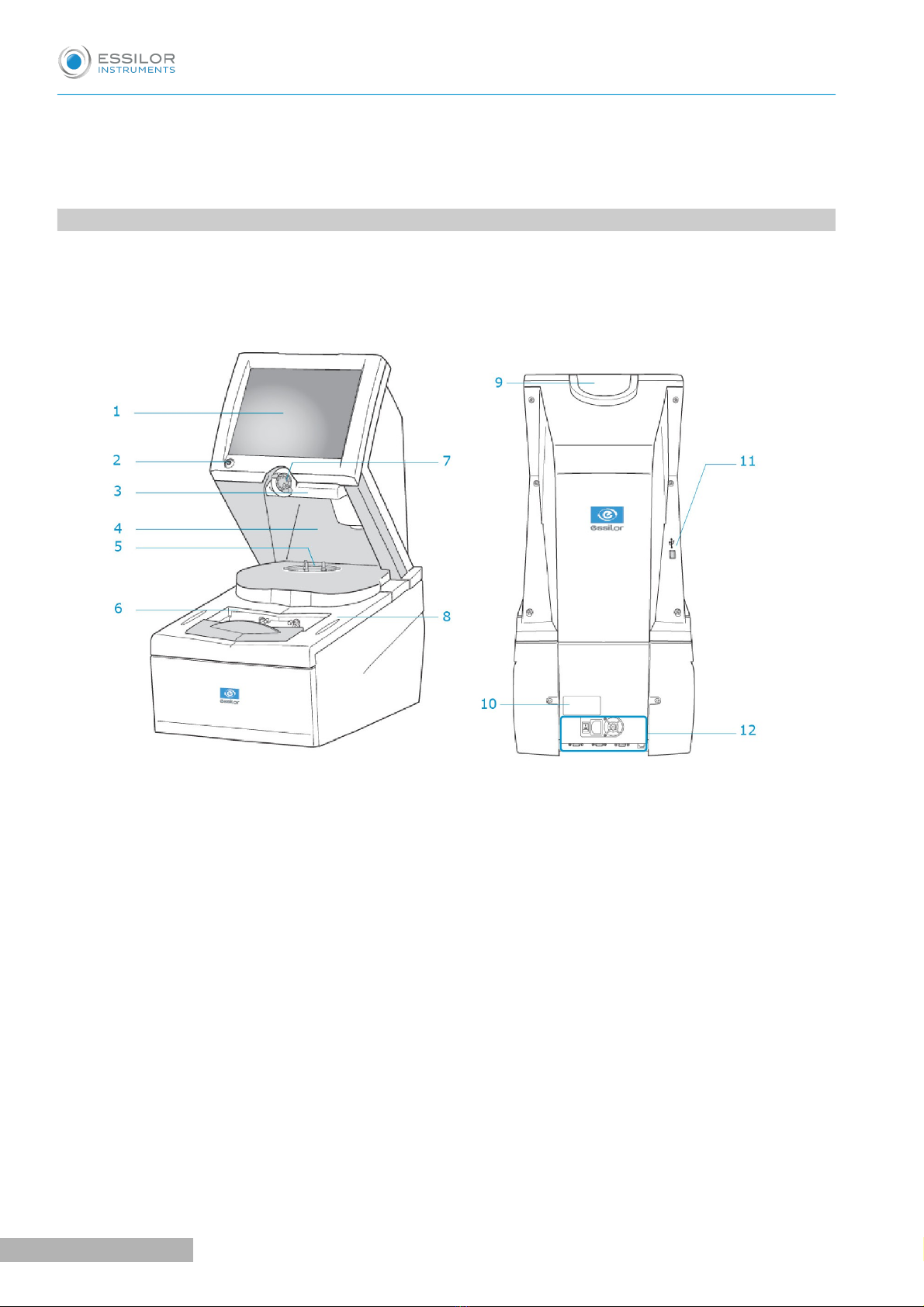
Tracer-centerer-blocker
1. Screen
2. ON/OFF button
3. Blocking arm
4. Centering chamber
5. Tripo
6. Tracing table (accor ing to version)
7. Blocking hea
8. Stylus rest
9. Tripo rest
10. Manufacturer plate
11. USB port
12. Connectors
Pro-B 300 > v .0 - 03. 9
10
USER MANUAL> I. FIRST STEPS

Connectors
1. Main switch
2. Power socket
3. Fan
4. Ethernet port
5. RS485 port
6. Barco e rea er port
7. Serial port
“Tracer-Centerer-Blocker” and blocker accessories
•Protective cover
•Pattern holder
•Bag of 22 mm posiblocks
•Bag of 8x 4 mm posiblocks
•Transport wedges to be kept
se accessories
•Stylus
•Standard tripod
•High-base tripod
•Recut accessory
•Small B-dimension wedges (quantity 2)
•White felt tip marker
•Roll of 22 mm pads
•Roll of 8x 4 mm pads
Maintenance accessories
•Calibration posiblock
•Pro-B 300 specific metal pattern gauge with table
•Pro-B 300 specific frame gauge (Black, Numbered) with Table
USER MANUAL> I. FIRST STEPS
11
Pro-B 300 > v .0 - 03. 9

•Pro-B 300 specific calibration gauge data SB Key with Table
Options
•Barcode reader
•Roll of barcode labels
•Start Pedal
Connection accessories
•Power cable
•RJ45 cable for the tracer-edger connection
•Essibox connection cable
2. INSTRUCTIONS FOR USE
In this section, you will find all the information concerning the following:
•Turning the device on (F p.12) and off (F p.12)
•The use of the touch screen and the keyboards, (F p.13)
•The description of the tracer work screen (F p.14).
a. Turning on device
Before the device is turned on, make sure the tracing table is empty (depending on the version).
To switch on the tracer, press the main switch located at the rear of the machine.
Press the ON/OFF button under the touch screen.
The device is initialized.
A beep indicates that the initialization was successful.
b. Turn off the device
Briefly press on the ON/OFF buttons located under the touch screen or press /, then .
Do not press the ON/OFF button for several seconds. This would result in shut-down of the device
and a warning message would be displayed at the next switch-on.
A confirmation message is displayed on each screen.
Press to confirm.
The device turns off.
>
>
>
>
1
2
3
1
2
Pro-B 300 > v .0 - 03. 9
12
USER MANUAL> I. FIRST STEPS

Extended period of non-use
For an extended period of non-use (a few days), it is best to turn off the device using the main switch.
c. sing the touch screen and keypads
sing the touch screen
Use the styli supplied with the machine to use the touch screens.
After each use, you can rest the stylus on one of the stylus rests, represented by oval stickers.
You can also touch the screen with your finger.
•If the screen is not sensitive enough to finger pressure, press lightly with a fingernail.
•If the reaction area does not correspond to the position of the key, you need to calibrate the touch
screen. For further information, refer to the section Maintenance and servicing > Check and calibrate
> Calibrate the touch screen (F p.121).
•Never press hard on the screen as this could break it.
•Never press on the screen with sharp objects such as pens, scissors, clamps, etc.
•Screen breakage is not covered by the guarantee.
On each screen, press the icon-buttons to access the desired menus and functions.
sing the keypads
When you need to enter or modify data, two types of keypads are automatically displayed, according to the
information to be entered.
•The numeric keypad is displayed for entering values.
•Reset the fields
•Go back
•Confirm
•Cancel and go back to the work screen
•The alphanumeric keypad is displayed to save or search for jobs.
USER MANUAL> I. FIRST STEPS
13
Pro-B 300 > v .0 - 03. 9
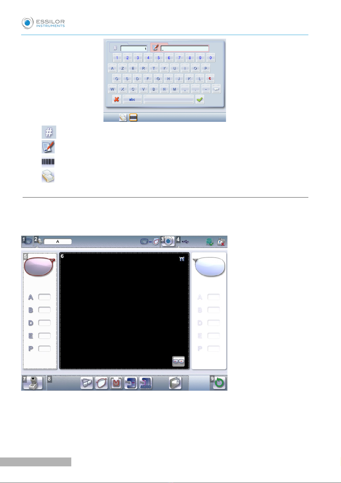
•Job ID
•Job reference (alphanumeric characters)
•Job list&
•Collection list
d. Tracing screen
Tracer-centerer-blocker
Main menus on the tracer-centerer-blocker screen:
1. Work screen in icator
2. Job information
3. Settings
4. Connecte evices
Pro-B 300 > v .0 - 03. 9
14
USER MANUAL> I. FIRST STEPS
5. Active eye an information on the shape
The right eye is selected by default.
The data on the left of the screen relates to the right eye, the data on the right of the screen relates to
the left eye.
6. Work area
7. Function buttons
◦Machine shutdown.
◦Tracing
◦Centering
◦Shape management
8. Actions available for the current screen
9. Tracing cycle initialization
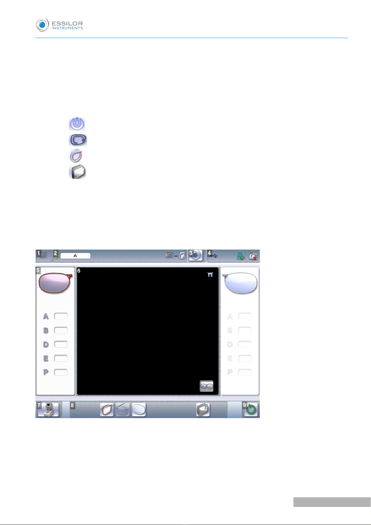
Centerer-blocker
Blocker screen main menus:
1. Work screen in icator
2. Job information
3. Settings
4. Connecte evices
USER MANUAL> I. FIRST STEPS
15
Pro-B 300 > v .0 - 03. 9

5. Active eye an information on the shape
The right eye is selected by default.
The data on the left of the screen relates to the right eye, the data on the right of the screen relates to
the left eye.
6. Work area
7. Function buttons
◦Machine shutdown
◦Tracing
◦Centering
◦Shape management
8. Actions available for the current screen
9. Tracing cycle initialization
Detailed functions
For more information, consult the section Perform a trace > Tracing environment > Legend screen.
(Fp.18)
Pro-B 300 > v .0 - 03. 9
16
USER MANUAL> I. FIRST STEPS

II. TRACING

This chapter describes the procedures for the tracing of all types of frames, patterns, demo lenses and recut
lenses:
•Description of the tracing environment (F p.18)
•Shape management and storage (F p.23)
•Tracing a rimmed frame (F p.28) (including high-base frame)
•Tracing a high-base frame (F p.30)
•Tracing a pattern, a demo lens or recut lens (F p.32)
. THE TRACING ENVIRONMENT
This section describes the tracing screen and explains how to manage the jobs:
•Description of the tracing screen (F p.18)
•Jobs and working modes (F p.21)
•Displaying the tracing completed in binocular mode (F p.22)
a. Legend screen
Tracer-centerer-blocker
1. Dimensions isplay
◦A: A-dimension
◦B: B-dimension
◦D: D-dimension
◦E: Larger radius from the Boxing center
◦P: Perimeter
2. Function buttons
◦Tracing
Pro-B 300 > v .0 - 03. 9
18
USER MANUAL> II. TRACING

◦Centering
◦Shape management
3. Tracing mo e
◦Rimmed frame (including high-base frame)
◦High-base frame
◦Optical tracing (patterns, demo lenses or recut lenses)
◦Mechanical tracing (patterns, demo lenses or recut lenses)
This mode cannot be selected. It is activated automatically upon detection of the pattern holder in
the tracing table.
4. Type of tracing
◦Symmetric binocular tracing&
◦Asymmetric binocular tracing&
◦Right-eye monocular tracing
◦Left-eye monocular tracing
5. Frame materials or type of optical tracing
For mechanical tracing of a frame:
◦Metal frame: high-precision tracing, with feeling of the groove cross-section
◦Plastic frame
◦Optyl frame, for particularly flexible frames
For optical tracing:
◦Demo lens//Recut lens for frame typeNylor ©
◦Demo lens / Recut lens
◦Pattern
◦Half jacket
For mechanical tracing of demo lenses, recut lenses or patterns, the tracer automatically detects the
pattern holder inserted in the tracing table.
6. Groove etection
◦: insertion in the middle of the frame (default value),
◦: high insertion (up to 75% the height frame),
◦: low insertion (up to 25% of frame height),
USER MANUAL> II. TRACING
19
Pro-B 300 > v .0 - 03. 9

7. Groove etection
◦: Automatic detection, default setting (systematically carried out on the metal frames).
◦: Groove acquisition never performed.
◦: Systematically groove acquisition performed.
8. Binocular view
9. New Job
For more information on jobs&, refer to the section Tracing > Shape management and storage (F p.23).
10. Tracing cycle initialization
Centerer-blocker
1. Dimensions isplay
◦A: A-dimension
◦B: B-dimension
◦D: D-dimension
◦E: Larger radius from the Boxing center
◦P: Perimeter
2. Function buttons
◦Tracing
◦Tracing
◦Centering
◦Shape management
Pro-B 300 > v .0 - 03. 9
20
USER MANUAL> II. TRACING
Table of contents
Other Essilor Laboratory Equipment manuals


Popular Laboratory Equipment manuals by other brands

Holland Green Science
Holland Green Science Antidrastiras DS150 user manual

Pfeiffer Vacuum
Pfeiffer Vacuum HIQUAD QMG 700 operating instructions

Agilent Technologies
Agilent Technologies CrossLab CS user manual

NanoEnTek
NanoEnTek EVE PLUS user manual

ASP
ASP Sterrad Velocity Reader user guide

Expedeon
Expedeon Gelfree 8100 user manual


Parker
Parker ALIGN-MG-NA Installation, operation and maintenance manual

Koehler
Koehler K88530 Operation and instruction manual

VWR
VWR INCU-Line IL 56 Short instruction manual

CETAC
CETAC ASX-260 Operator's manual
Specac
Specac ARROW Quick start manual

CertoClav
CertoClav Vacuum Pro Series instruction manual