Esteam E300 User manual

1
Operating Manual
E300 SPOTTER
2
E300 SPOTTER Operating Manual
TABLE OF CONTENTS
TOPIC PAGE #
!Introduction 3
!Technical Specifications 4
SECTION 1: Operational Safety
!Electrical Safety 5
!Mechanical Safety 6
SECTION 2: Operation Procedures
!Electrical Supply 7
!Water Supply & Chemicals 7
!Solution & Vacuum Hoses 7
!Starting System - Switches 8
!Shutdown Procedures 9
!Troubleshooting 10-11
!Solution Flow Path E300 12
!Wiring Diagrams E300 14
SECTION 3: Maintenance/ Technical
!Maintenance
18
!Parts 21
oE300 22
oHoses & Tool
36
!Warranty 37

3
Introduction
Congratulations on your purchaseof the E300 SPOTTER. The E300 is designed
to combine versatility with easeof transport. Years of experience, engineering,
and planning havegone into the design and manufacturing of the E300
SPOTTER. We take agreat deal of pride in the E300 SPOTER; our goal is no
lessthan your complete satisfaction.
This manual will provide users with the knowledge required to operate the E300
SPOTTER safely, to understand how to properly operateand maintain the
machine, and to ensurethat the equipment operates at its maximum performance
level.
All users must read and understand this manual completely before
operating the machine.
Always maintain this manual in legible condition adjacent to the E300 SPOTTER,
or placein asecure location for futurereference.
4
Technical Specifications
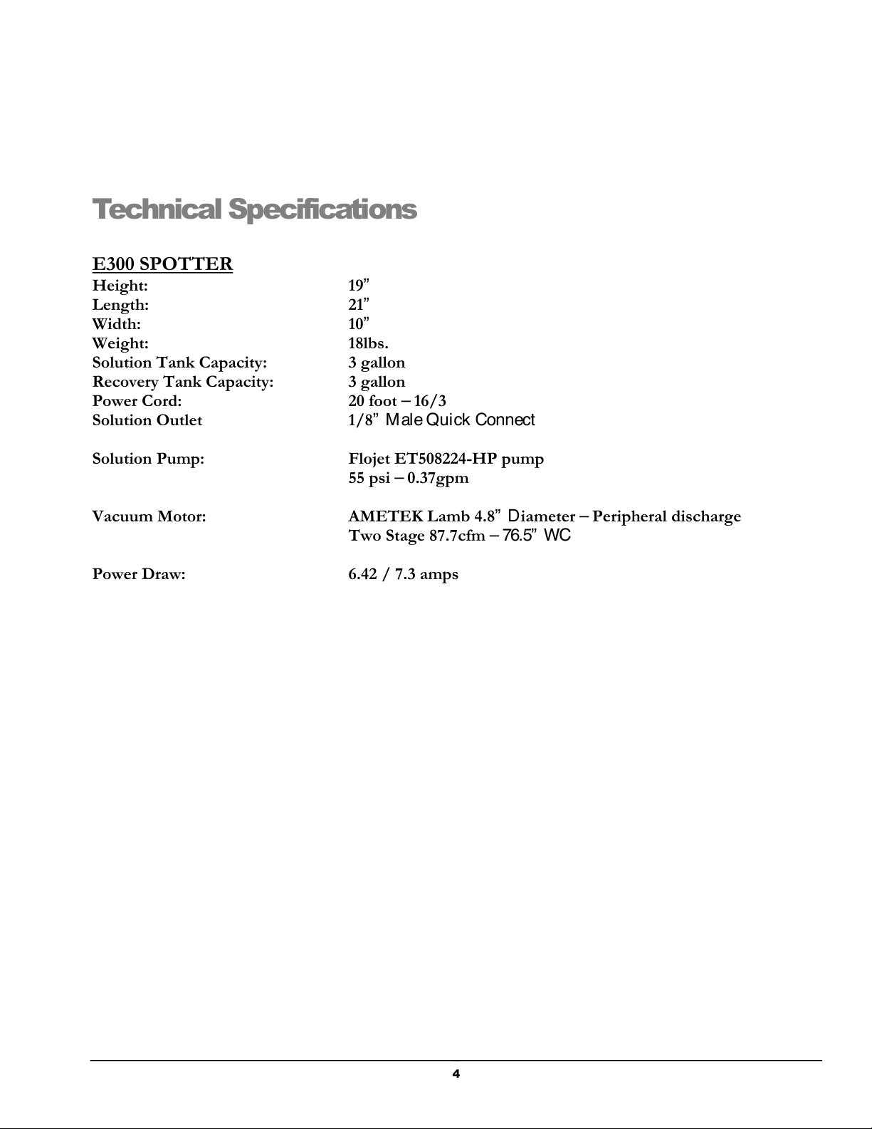
E300 SPOTTER
Height: 19”
Length: 21”
Width: 10”
Weight: 18lbs.
Solution Tank Capacity: 3 gallon
Recovery Tank Capacity: 3 gallon
Power Cord: 20 foot –16/3
Solution Outlet 1/8” Male Quick Connect
Solution Pump: Flojet ET508224-HP pump
55 psi –0.37gpm
Vacuum Motor: AMETEK Lamb 4.8” Diameter –Peripheral discharge
Two Stage 87.7cfm – 76.5” WC
Power Draw: 6.42 / 7.3 amps

5
Safety
CAUTION! This machine is an electrical appliance. Care must be
taken to reduce the risk of electrical shock.
!READ AND UNDERSTAND ALL INSTRUCTIONS BEFORE OPERATING THE E300
SPOTTER.
!To reduce therisk of property damage or injury, repairsto electrical systemsshould only beperformed by
experienced technicians. Contact your distributor for assistance. Unplug machine power cord from outlet
before performing any repairson the extractor.
!This machineshall begrounded whilein useto protect theoperator from electric shock. The machine is
provided with athree-conductor cord and athree-contact grounding typeattachment plug to fit the
proper grounding typereceptacle. The green (or green and yellow) conductor in the cord isthegrounding
wire. Never connect thiswire to other than the grounding pin of the attachment plug.
!This machineisfor useon anominal 120-volt circuit and
hasagrounding plug that resembles the plug illustrated in
the sketch to the right. Make surethat the machine is
connected to an outlet having the sameconfiguration as
the plug. No plug adapter should be used with this
machine.
!Thepower cord supplied with thismachine is properly
sized to handle theelectrical load of thismachineand
properly grounded asdescribed above. Any extension
cords used with this machine must be similarly sized and
grounded to assure safe operation. A properly sized
GFCI protected cord can beused for additional protection.
!Do not usetheE300 SPOTTER outdoors, in standing water or on wet surfaces. Do not storetheE300 in wet
conditions. If extractor is leaking, unplug machine power cords from outlets before approaching or touching
machine.
!Do not unplug power cord by pulling on thecord. Grasp theplug end when unplugging thecord. Do not pull
the extractor by the cord. If cord or plug is damaged, do not use cord. Replace with new cord or repair as
needed beforeuse.
!Overloaded circuit may not always trip circuit breaker. Reduced voltage to machine on overloaded circuit will
prevent componentsfrom operatingproperly.
Section
1
Table of contents
Other Esteam Cleaning Equipment manuals

Popular Cleaning Equipment manuals by other brands


Suevia
Suevia 130.5011 EASYCLEANER Mounting instructions

i-MO
i-MO Öko 2000 user guide

unGer
unGer Hydro Power Ultra UNP01 operating instructions

Black & Decker
Black & Decker BHPC130 Original instructions

Uni-ram
Uni-ram UG5000E operating manual

Axi
Axi MTC HC-300 Installation, operating and maintenance manual