ESTeem 195Eg User manual

ESTeem MODEL 195E SERIES
USER’S MANUAL
Models 195Eg – 195Ed - 195Ep – 195Ea
Manual Revision 1.0
October 2012
Electronic S
y
stems Technolo
gy,
Inc.

Author: Date:
Name: Eric P. Marske
Title: Product Support Manager
Approved by: Date:
Name: Tom L. Kirchner
Title: President
Electronic Systems Technology, Inc.
Building B1
415 N. Quay Street
Kennewick, WA 99336
Phone: 509-735-9092
Fax: 509-783-5475
E-mail: [email protected]
Web Site: www.esteem.com
Copyright© 2013 by Electronic Systems Technology, Inc.
All rights reserved. Printed in the United States of America. No part of this publication may be reproduced, stored
in a retrieval system, or transmitted, in any form or by any means, electronic, mechanical, photocopying, recording,
or otherwise, without the prior written permission of Electronic Systems Technology.

PRODUCT WARRANTY
ELECTRONIC SYSTEMS TECHNOLOGY, INC. Specifications subject to change without notice
415 North Quay Street •Kennewick, WA 99336 www.esteem.com
Phone (509) 735-9092 •Fax (509) 783-5475 Revised: 28 Aug 2013
Electronic Systems Technology, Inc., (hereinafter EST) expressly warrants its products as free of manufacturing defects for a period
of one year from the date of sale to first user/customer. THERE ARE NO OTHER WARRANTIES, EXPRESS OR IMPLIED AND
THERE IS EXPRESSLY EXCLUDED ALL WARRANTIES OF MERCHANTABILITY OR FITNESS FOR A PARTICULAR
PURPOSE. NO OTHER WARRANTY GIVEN BY ANY EMPLOYEE, AGENT, DISTRIBUTOR OR OTHER PERSON WITH
RESPECT TO THE PRODUCT SHALL BE BINDING ON EST.
LIMITATION OF LIABILITY:
EST's liability shall be limited to refunding of purchase price, repair or replacement of product. IN NO EVENT SHALL EST HAVE
LIABILITY FOR CONSEQUENTIAL, INCIDENTAL, SPECIAL OR EXEMPLARY DAMAGES CAUSED DIRECTLY OR
INDIRECTLY BY THE PRODUCT, INCLUDING BUT NOT LIMITED TO ANY INTERRUPTION OF SERVICES, LOSS OF
BUSINESS OR ANTICIPATORY PROFITS. IN NO EVENT SHALL EST BE LIABLE FOR ANY DAMAGES WHATSOEVER IN
EXCESS OF THE PURCHASE PRICE OF THE PRODUCT.
In the event that a unit or part requires replacement or factory servicing, the following conditions apply:
a) Customer must obtain from EST an authorized RMA (Return Materials Authorization) Number before shipment of product
or parts to EST for any reason;
b) If the whole unit is shipped, it must be in its original carton and shipping components, or a carton and shipping components
supplied by EST, or it parts only are shipped, they must be packaged and cushioned so as to prevent damage in transit
and shipped freight prepaid;
PRODUCT WILL BE CONSIDERED OUT OF WARRANTY IF:
a) If the product is damaged due to improper or abnormal use, abuse, mishandling, accident or improper maintenance or
failure to follow operating instruction;
b) If the product is defective as a result of sand, dirt, or water damage;
c) If any factory-sealed enclosure has been opened or shows evidence of an attempt to be opened;
d) If defects or damage are caused by the use of unauthorized parts or unauthorized service;
e) If the product has had its serial numbers altered or removed.
Warranty repair form must be accompanied by proof of user's purchase of unit. Product must be shipped to the manufacturer at the
following address:
Electronic Systems Technology
415 North Quay Street
Kennewick, Washington USA 99336
ADDITIONAL SERVICE:
If EST releases an improvement update to firmware internal to the ESTeem unit during the 90 day period after the unit was
purchased by the first user/customer, EST will update the applicable unit with the revised version at no charge other than for UPS
handling and shipping to and from your location to the EST factory. Return of any such item must be accompanied with proof of
purchase.

TABLE OF CONTENTS
Revised: 30 Oct 12 Page 1 EST P/N AA107G
CHAPTER 1 – Introduction
Before You Begin 1-1
Model 195E Overview 1-1
Model 195E Configuration Modes 1-1
Access Point Modes --------------------------------------------- 1-2
Access Point Repeater --------------------------------------------- 1-3
Self-Healing Mesh Network --------------------------------------------- 1-3
Station (802.11g Client) Modes --------------------------------------------- 1-4
RS-232 Serial Applications --------------------------------------------- 1-5
CHAPTER 2 – Starting Out
Three Configuration Phases 2-1
Model 195E Hardware Description 2-1
Front Panel Layout --------------------------------------------- 2-2
Antenna Connection Overview --------------------------------------------- 2-2
Model 195Eg Hardware Configuration 2-3
CHAPTER 3 – Example Applications
Modes of Operation Description and Examples 3-1
Ethernet Bridge Mode --------------------------------------------- 3-1
Router Modes --------------------------------------------- 3-3
Mobile Client Modes --------------------------------------------- 3-4
802.11 Access Point Modes --------------------------------------------- 3-5
Programming Examples 3-7
Using ESTeem Network Configuration (ENC) Utility --------------------------------------------- 3-7
Example 1 – Point to Point Ethernet Bridge --------------------------------------------- 3-9
Example 2 – Point to Point Ethernet Bridge with Repeater --------------------------------------------- 3-10
Example 3 – Point to Multipoint with Mesh Repeater --------------------------------------------- 3-11
Example 4 – Point to Multipoint Router Mode --------------------------------------------- 3-13
Example 5 – Mobile Client Mode --------------------------------------------- 3-15
Example 6 – 802.11 Access Point Mode --------------------------------------------- 3-16
Router Addressing Examples --------------------------------------------- 3-17
CHAPTER 4 – Utilities and Features
ESTeem Network Configuration (ENC) Utility --------------------------------------------- 4-1
Using ESTeem Discovery Program --------------------------------------------- 4-2
Using EtherStation Status Program --------------------------------------------- 4-5
Setting Local Time 195Eg --------------------------------------------- 4-6
Configuring Time Server --------------------------------------------- 4-7
VLAN Operation --------------------------------------------- 4-9
IGMP Snooping --------------------------------------------- 4-10
Simple Network Management Protocol (SNMP) --------------------------------------------- 4-15

TABLE OF CONTENTS
Revised: 30 Oct 12 Page 2 EST P/N AA107G
CHAPTER 5 – Web Configuration
Logging Into Web Configuration Manager 5-1
Web Configuration Manager 5-2
Top Menu --------------------------------------------- 5-2
Setting ModemID Field --------------------------------------------- 5-2
Status Menu --------------------------------------------- 5-3
System Log Screen --------------------------------------------- 5-5
Setup Screen --------------------------------------------- 5-5
Advanced Configuration Screen --------------------------------------------- 5-6
Backup Screen --------------------------------------------- 5-6
Restore Screen --------------------------------------------- 5-7
Software Update --------------------------------------------- 5-8
System Reboot --------------------------------------------- 5-8
CHAPTER 6 – Serial Configuration and Applications
Using RS-232 Programming Port 6-1
Using RS-232 Data Port 6-3
Second Connections --------------------------------------------- 6-3
Second Configuration --------------------------------------------- 6-3
CHAPTER 7 – Repeating and Mesh Networking
ESTeem Mesh Network 7-1
Configuration --------------------------------------------- 7-1
Rapid Spanning Tree Protocol (RSTP) 7-2
Spanning Tree Protocols (STP) 7-3
Overview --------------------------------------------- 7-3
Phases --------------------------------------------- 7-4
Priority and Path Cost --------------------------------------------- 7-4
Root Bridge --------------------------------------------- 7-4
Redundant Backup 7-5
Redundant Master Configuration --------------------------------------------- 7-5
CHAPTER 8 – Antenna Setups
Antenna and Cable Configurations 8-1
Model 195Eg/195Eg-lp Antenna and Cable Configuration --------------------------------------------- 8-1
Model 195Ea Antenna and Cable Configuration --------------------------------------------- 8-3
Model 195Ed Antenna and Cable Configuration --------------------------------------------- 8-4
Model 195Ep Antenna and Cable Configuration --------------------------------------------- 8-5
Weatherproofing Coaxial Cable Connections 8-6
Antenna Diversity 8-6
Antenna Port Selection --------------------------------------------- 8-7

TABLE OF CONTENTS
Revised: 30 Oct 12 Page 3 EST P/N AA107G
Assembling the AA195PM Outdoor Pole Mounting Kit 8-9
195E Grounding Procedure 8-14
Fresnel Zone 8-15
APPENDIX A – FCC Information
APPENDIX B – Interface Ports
Ethernet Interface --------------------------------------------- B-1
Configuring DHCP Server --------------------------------------------- B-1
RS-232 Programming Port Pin-Out --------------------------------------------- B-2
RS-232 Data Port Pin-Out --------------------------------------------- B-2
APPENDIX C – Radio Configuration
Frequency of Operation --------------------------------------------- C-1
Setting RF Bandwidth --------------------------------------------- C-2
Setting Data Rates --------------------------------------------- C-2
Setting RF Power Level --------------------------------------------- C-3
Average RF Output Power --------------------------------------------- C-4
APPENDIX D – Security
APPENDIX E – Troubleshooting
Testing Communication Link --------------------------------------------- E-1
Viewing RF Data Rates --------------------------------------------- E-3
Signal Strength vs Data Rates --------------------------------------------- E-4
Setting Maximum Distance Value --------------------------------------------- E-4
Troubleshooting Tips --------------------------------------------- E-5
APPENDIX F – 195Eg Specifications
195Eg Specifications --------------------------------------------- F-1
Case Diagram --------------------------------------------- F-2
Antenna Specifications --------------------------------------------- F-3
APPENDIX G – 195Ea Specifications
195Ea Specifications --------------------------------------------- G-1
Case Diagram --------------------------------------------- G-2
Antenna Specifications --------------------------------------------- G-3
APPENDIX H – 195Ed Specifications
195Ed Specifications --------------------------------------------- H-1
Case Diagram --------------------------------------------- H-2
Antenna Specifications --------------------------------------------- H-3
APPENDIX I – 195Ep Specifications
195Ep Specifications --------------------------------------------- I-1
Case Diagram --------------------------------------------- I-2
Antenna Specifications --------------------------------------------- I-3
APPENDIX J – 195Eg-lp Specifications

CHAPTER 1
INTRODUCTION
Revised: 19 Oct 12 1-1 EST P/N AA107E
BEFORE YOU BEGIN
Thank you and congratulations on your purchase of the ESTeem
Model 195E Wireless Ethernet Radio Modem! This manual was
written to help both the first time and advanced user of the 195E to
configure the wireless modem for your application. If this is your
first time configuring the 195E and you would like to get going as
soon as possible, we recommend using the ESTeem Resource CD
provided with the modem. The Resource CD will provide the
software utilities and guide you through the configuration of the
wireless modem for your application.
The ESTeem 195E series wireless modems are very sophisticated
networking devices. To keep the manual usably short, many of the application descriptions and programming details assume
the user has a good working knowledge of the following network concepts:
•General Ethernet networking and the configuration of LAN topologies
•Common Ethernet terminology and acronyms
•TCP/IP network protocol structure and how to configure TCP/IP networks
and subnets
•How to identify and set the TCP/IP address on your computer
•Have administrator privileges to the computer and network you are configuring
•If using routing protocols, you must be able to identify and configure the network routers, gateways and firewalls
•You must be familiar with using web browser software such as Internet Explorer, Netscape or Mozilla
If you are unfamiliar with any of the above networking concepts, you may need to contact your network administrator for
assistance.
MODEL 195E OVERVIEW
The ESTeem Model 195E is a series of wireless
LAN transceivers that can be used to build many
types of Wireless Local Area Networks (WLAN).
The wireless modems in 195E series can provide
RF data rates up to 54 Mbps and have an RS-232
serial port for legacy device networks. The Model
195E is a very sophisticated networking device
that can be configured for multiple modes of
operation depending upon the needs of the wireless
and wired LAN system. The following
configuration modes are provided as an overview
of the basic network types, as all possible network
configurations can not be listed. For further help
in selecting the correct network type, please refer
to Chapter 4 of this User’s Manual or call
Customer Support at 509-735-9092.
Figure 1: ESTeem Model 195E Series
Throughout this User’s Manual are
“Technical Tips” in boxes like this that
have been added to help answer the
most commonly asked questions.
Figure 2: Access Point Bridge Diagram
CHAPTER 1
INTRODUCTION
Revised: 19 Oct 12 1-2 EST P/N AA107E
CONFIGURATION MODES
A Model 195E can be configured for multiple
modes of operation without any changes to the
hardware. The following are brief descriptions
of the configuration modes. For detailed
descriptions and suggested applications for
each mode, please refer to Chapter 4.
Access Point Modes
When a Model 195E is configured as an Access
Point it will provide a wireless bridge for
mobile clients such as Model 195E modems in
client modes or Wi-Fi devices with the 195Eg
and 195Ea. Multiple Access Points can be
physically connected to the same network
(LAN) or through a radio link using the Access
Point Repeater mode to provide overlapping,
seamless Ethernet communication for mobile
devices. Figure 3: Repeater Mode Diagram
1. Access Point Bridge Mode
An ESTeem Model 195E in Access Point Bridge mode will both provide wireless access to mobile clients (Access Point)
and bridge all Ethernet data connected to the Ethernet ports. The AP Bridge mode will pass all network traffic between
connected devices including global network broadcasts. (See Figure 2)
2. Access Point Router Mode
In this mode the ESTeem Model 195E will function as a router between wired Ethernet networks, connected to the
195E’s Ethernet port, and the
wireless clients in the network. As in
all standard router configurations, the
wireless and wired Ethernet networks
will need to be on separate subnets.
The 195E in Access Point Router
mode will pass network traffic for
connected devices but will block
global network broadcasts from the
wired network. This mode of
operation should be used instead of
the Access Point Bridge mode when
a separation between networks is
required or the ESTeem is connected
to larger LAN Networks that will
continuously send global network
broadcasts (Figure 3).
Figure 4: Access Point Masquerade Diagram

CHAPTER 1
INTRODUCTION
3. Access Point Masquerade Mode
The Access Point Masquerade mode is a special use of the Access Point mode where the Model 195E will connect
mobile clients into a single static IP address on a wired network. Data requests from the wireless network will be
processed through the Access Point Masquerade 195E, but any request from the wired Ethernet network to devices on the
wireless network will be rejected similar to the operation of a “firewall”. The 195E will hide all the IP addresses
connected on the wireless link. You would use this mode of operation if Model 195E is connected directly to the Internet
with a static IP address (DSL, T1, etc.) and you want the wireless clients to access the information through the Model
195E (Figure 4). This mode should also be used for attaching the Model 195E to a network where few IP addresses are
available or a firewall for the wireless clients is required.
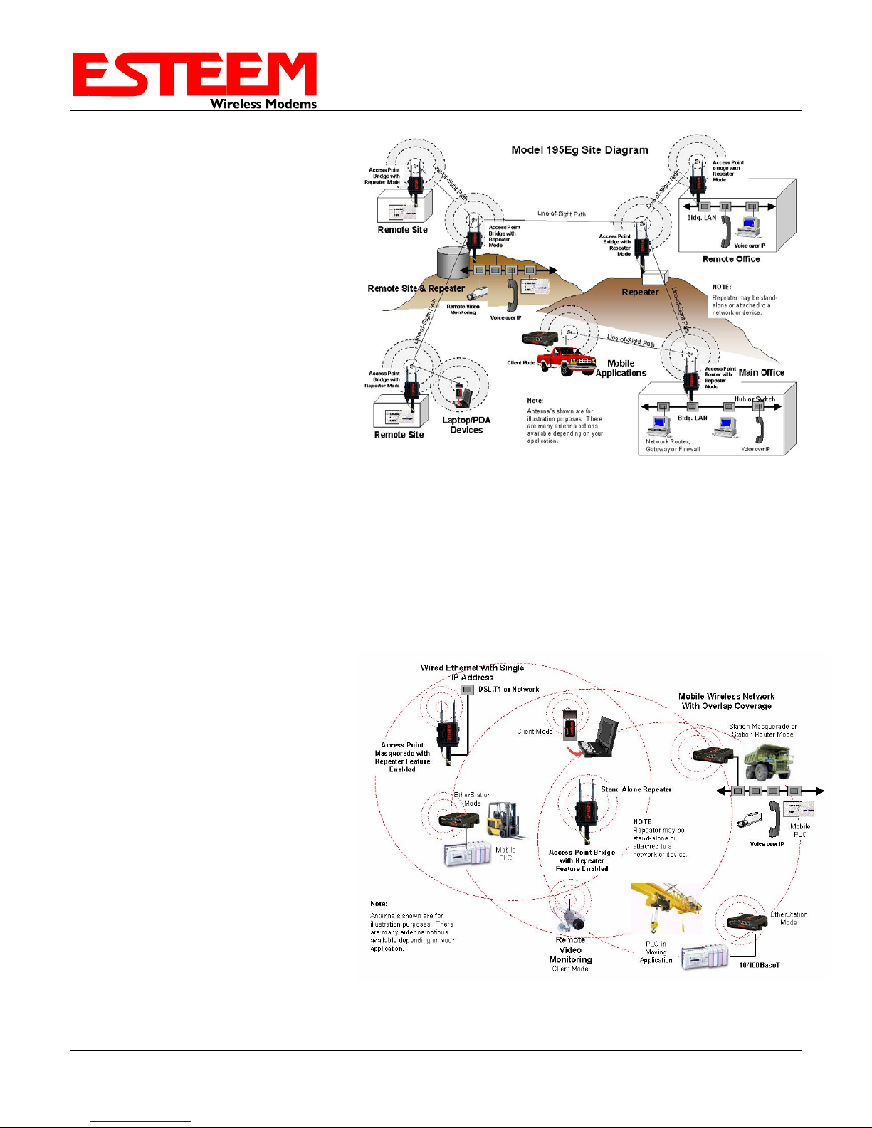
Access Point Repeater
The Access Point Repeater is a unique enhancement of the ESTeem Model 195E series. The Access Point Repeater can
be used with any of the above Access Point modes. With this repeater feature enabled, the Model 195E Access Points do
not have to be hardwired together on the same physical LAN to provide seamless Ethernet communication for roaming
clients. In addition to greatly extending the Access Point canopy range, the Model 195E will also bridge any Ethernet
device or Ethernet network connected to the unit over this same wireless Ethernet network. This mode gives the user the
features of a point to multi-point bridge network but also allows the Model 195E in the Client mode to simultaneously
roam under the network canopy.
Self-Healing Mesh Network
If multiple Access Point Repeater routes are configured to the same destination ESTeem, the 195E will create a “self-
healing” mesh network by automatically re-routing data through alternate paths to reach its destination if the primary
path is inoperable. The routing and priority of alternate paths is completely user configurable. (See Figure 5)
Main Office
Remote Office
Vehicles
Remote Site
Remote Site
Remote Site
Access
Point/Repeater
Access
Point/Repeater
Remote Site
Access
Point/Repeater
Access
Point/Repeater
Access
Point/Repeater
Remote Site
Access
Point/Repeater
Remote Site
Access
Point/Repeater
Remote Site
Access
Point/Repeater
Remote Site
Access
Point/Repeater
Access
Point/Repeater Access
Point/Repeater
Access
Point/Repeater
Remote Site
Remote Site
Client Mode
Figure 5: Mesh Network Diagram
Revised: 19 Oct 12 1-3 EST P/N AA107E

CHAPTER 1
INTRODUCTION
Revised: 19 Oct 12 1-4 EST P/N AA107E
Station (Client) Modes
1. EtherStation Mode
When the 195E is configured in the EtherStation mode and attached to a single Ethernet Device, the Model 195E will
emulate an 802.11 wireless card in functionality for communication as a mobile client. The 195E will seamless roam
under the radio canopy of Access Points and can provide greatly increased range over a Wireless LAN Card for mobile
Ethernet devices such as vehicles, forklifts, cranes, etc (Figures 2-4).
2. Station Router Mode
The Station Router mode will also functions as a mobile client, similar to EtherStation, but will allow multiple Ethernet
devices to be connected to a single 195E (Figure 4). The 195E will function as a router between the wireless client mode
and the wired Ethernet devices connected to the Ethernet port. Similar in configuration to the Access Point Router mode,
the wireless and wired Ethernet networks will need to be on separate subnets. To communicate from wireless network to
devices on the wired Station Router network, a separate router (connected to the Ethernet side of the Access Point) is
required. This mode would be used where multiple Ethernet devices will be connected to a single Model 195E in a
mobile client application and the connected Ethernet devices will need to be accessible from the Access Point’s LAN
network.
3. Station Masquerade Mode
The Station Masquerade mode is another case multiple devices will be connected to a single ESTeem in a mobile or
client application. However, unlike the Station Router mode, the Station Masquerade will consolidate all connected
Ethernet devices to a single IP address on the network. The devices connected to the Station Masquerade 195E will be
able to access information from both the wireless and wired LAN, but will be inaccessible the other way similar in
application to a firewall. This mode would be used where multiple Ethernet devices will be connected to a single Model
195E in a mobile application and the IP addresses for each device will be hidden from the LAN connected to the Access
Point. See Figure 4.

CHAPTER 1
INTRODUCTION
RS-232 Serial Applications
The ESTeem 195E is installed with an RS-232 data port for serial data applications run over the broadband link (Figure
6). The serial over broadband network can be used in a point-to-point or point-to-multi-point application for networking
serial (RS-232C) devices, providing serial connections to legacy hardware in a new Ethernet network or providing for
high-bandwidth devices (such as Video or Voice over IP) in an existing serial network.
Remote Site & Repeater Repeater
Remote Site
Access Point
Bridge with
Repeater Mode
Remote Site
Access Point
Bridge with
Repeater
Mode
Access Point
Bridge with
Repeater
Mode
Access Point
Bridge with
Repeater Mode
Access Point
Bridge with
Repeater
Mode
Line-of-SightPath
NOTE:
Repeater may be stand-
alone or attached to a
network or device.
Line-of-SightPath
Line-of-Sight Path
Line-of-SightPath
Line-of-SightPath
Access Point
Bridge with
Repeater
Mode
Note:
Antenna’s shown are for
illustration purposes. There
are many antenna options
available depending on your
application.
Master PLC
RS-232 Data
Remote PLC
RS-232 Data
RS-232 Data
RS-232 Data
RS-232 Data
Figure 6: Multi-point Serial Diagram
To begin setup of your wireless Ethernet network, continue to Chapter 2 - Staring Out of this User’s Manual.
Revised: 19 Oct 12 1-5 EST P/N AA107E
CHAPTER 2
STARTING OUT
Revised: 19 Oct 12 2-1 EST P/N AA107E
OVERVIEW
There are three main phases to prepare the ESTeem 195E for operation in a wireless network:
Phase 1 - Determine the correct mode of operation for the ESTeem in the wireless network. The ESTeem 195E is a
sophisticated networking device that can be configured for multiple modes of operation. Determining the correct mode of
operation for the ESTeem 195E is the first step. Chapter 3 of this User’s Manual details the modes of operation and applications
where each would be used.
Phase 2 - Program the ESTeem for operation in the wireless network. Once the correct mode of operation for the ESTeem
has been determined, the 195E can be programmed for the wireless network. To simplify the programming of the Model 195E,
ESTeem has created a new software utility called the ESTeem Network Configuration (ENC) Utility which is used to graphically
configure the primary and backup communication routes between ESTeem 195E’s in the network. The ENC Utility can be
installed from the ESTeem Resource Disk or from the ESTeem web site (www.esteem.com). Chapter 4 (Utilities and Features) of
this User’s Manual will guide you in the installation of the software and give a brief overview of operation of the ENC Utility, but
a detailed User’s Guide is available both on the ESTeem Resource Disk and in the Help section of the program itself.
The ESTeem Model 195E can also be programmed through the internal Web interface (discussed in detail in Chapter 5) if you do
not have access to the ENC Utility or your firmware version is older version 799.
Phase 3 - Install the ESTeem hardware and test communication. After the ESTeem Model 195E’s programming, install the
hardware in each remote location. Chapter 8 of this User’s Manual describes the antenna specifications, mounting options and the
configuration of the pole mounting hardware for the ESTeem. For instructions on testing and troubleshooting the wireless link,
refer to Appendix E(Troubleshooting).
MODEL 195E HARDWARE LAYOUT
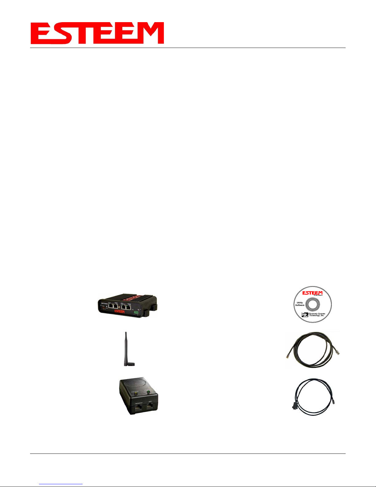
To begin the configuration, unpack the ESTeem Model 195E shipping boxes and locate the items below for initial configuration.
Take a few minutes to inventory your equipment before you proceed. Report any missing or damaged items to Customer Support
(509-735-9092) as soon as possible. Each node in your ESTeem Model 195E’s network may have different hardware
components based upon the final installation location (i.e. Outdoor, Indoor, Point-to-point or Muti-Point). Antenna types, cable
lengths, power supplies may be different, but the following items will be required for basic setup:
Model 195E
AA109 Resource Disk
Antenna
(AA01S Displayed)
(2) Ethernet Cables
Power Supply
(AA175 Displayed)
Serial Interface Cable
(AA6021.1)
Note: Your accessory model numbers may vary from the above, but you will need to locate each of above items to continue
configuration.

CHAPTER 2
STARTING OUT
Revised: 19 Oct 12 2-2 EST P/N AA107E
Figure 1: 195E Front Panel Overview
Figure 2: 195E Antenna Overview

CHAPTER 2
STARTING OUT
Revised: 19 Oct 12 2-3 EST P/N AA107E
MODEL 195E HARDWARE CONFIGURATION
The following steps should be completed to begin configuration of the ESTeem Model 195E:
1. Connect the antenna to the antenna connector on the ESTeem Model 195E (Figure 3). For a single antenna use Antenna Port
A and connect both if using dual antennas.
2. Assemble the 195E hardware as shown in Figure 4.
Leave
Open
Single Antenna
Configuration Dual Antenna
Configuration
Figure 3: Antenna Configuration Diagram
Figure 4: Hardware Configuration Diagram
Technical Tips:
1. Configure the Model
195E prior to mounting.
2. Attach antenna to the
Model 195E before
powering up.

CHAPTER 3
EXAMPLE APPLICATIONS
MODES OF OPERATION
The ESTeem Model 195E is a sophisticated wireless networking device that can be configured for multiple modes
of operation. Determining the correct mode of operation for the ESTeem is the first step in creating a reliable
wireless network. This chapter will explain each mode of operation, provide example applications and detailed
programming information for each mode. Please review the following modes of operations. If you do not see an
example of your application, please contact ESTeem support at 509-735-9092 for help in selecting your mode of
operation.
Ethernet Bridge Mode (AP Bridge)
The most commonly used mode of operation with the ESTeem Model 195E is the Ethernet bridge mode. The
Ethernet bridge mode will connect two or more ESTeem 195E’s while passing all network traffic that arrives in both
the wireless and connected Ethernet ports; including all global network traffic (Figure 1). This mode will work in
most wireless applications of the 195E to wirelessly connect two or more remote Ethernet devices or networks. The
Ethernet bridge mode is also used in repeating (Figure 2) and in self-healing Mesh networks (Figure 3) for fixed
(non mobile) applications.
Example Applications
•Building to building remote wireless LAN networks
•Point to point wireless Ethernet communication devices
•Multi-point wireless Ethernet networks
•Remote Supervisory Control and Data Acquisition (SCADA) networks
•Redundant, self-healing Mesh networks
•Fixed locations with mobile ESTeem 195E’s
Applications Where Ethernet Bridge Mode Not Used
•Mobile applications (see Mobile Clients)
•Connections to large Ethernet traffic networks such as large office buildings or plant networks (see Router
modes)
Revised: 19 Oct 12 3-1 EST P/N AA107E
Figure 1: Point to Point Example

CHAPTER 3
EXAMPLE APPLICATIONS
Figure 2: Ethernet Bridge with Repeater
Figure 3: Multipoint Bridge with Mesh Networking
Revised: 19 Oct 12 3-2 EST P/N AA107E

CHAPTER 3
EXAMPLE APPLICATIONS
Router Modes (AP Router and AP Masquerade)
The ESTeem 195E can be configured as a network router or network firewall between the Ethernet LAN connection
and the wireless network of remote locations. The router modes are used to limit the network traffic from a busy
Ethernet network connection to only those specific IP address used on the wireless network (see Figure 4). The
Ethernet router mode (AP Router) will allow bi-directional communication from the Ethernet LAN connection to the
wireless network. The Ethernet firewall mode (AP Masquerade) will allow Ethernet devices in the wireless network
to request information from the Ethernet LAN network and receive a response, but no traffic can be generated from
the Ethernet LAN side.
Example Applications
•Wireless Ethernet networks connected to large company or plant Ethernet LAN networks (AP Router)
•Wireless Ethernet networks with a requirement for network isolation from the plant or company network
(AP Router)
•Shared Ethernet connection to direct Internet service (DSL, Cable, T1, etc.) (AP Masquerade)
Applications Where Ethernet Router Mode Not Used
•Mobile applications (see Mobile Clients)
•Simple network connections only using a single IP network subnet (see Ethernet Bridge modes)
Figure 4: Router Mode Example
Revised: 19 Oct 12 3-3 EST P/N AA107E

CHAPTER 3
EXAMPLE APPLICATIONS
Mobile Client Modes (EtherStation, Station Router or Station Masquerade)
The ESTeem 195E can also be configured to function as a mobile client. The client modes allow the 195E to
seamlessly roam between fixed Access Points. These Access Points can either be ESTeem 195E wireless
modems configured in one of the three Access Point modes (AP Bridge, AP Router or AP Masquerade – see
above) or any IEEE 802.11 (Wi-Fi) Access Point for the ESTeem 195Eg and 195Ea. The client modes will allow
mobile Ethernet devices to connect to each other or to an Ethernet LAN through the fixed AP (Figure 5).
The EtherStation mode is used to connect a single Ethernet device to the ESTeem 195E. If you are connecting the
195E to multiple Ethernet devices in a mobile mode, the Station Router or Station Masquerade will be required.
The Station Router will allow bi-directional communication between the Ethernet devices connected to the 195E
and the wireless network, while the Station Masquerade will serve as a firewall on the Ethernet side.
Example Applications
•Mobile applications where the 195E will change links often between fixed Access Points
•Long range mobile client networks
•Public safety applications for police, fire and EMS
Applications Where Mobile Client Mode Not Used
•Fixed locations using Ethernet Bridging or Routing
•Wireless Ethernet networks with repeaters
Figure 5: Router Mode Example
Revised: 19 Oct 12 3-4 EST P/N AA107E

CHAPTER 3
EXAMPLE APPLICATIONS
802.11 Access Point Modes (AP Bridge, AP Router or AP Masquerade) (195Eg and 195Ea Only)
The ESTeem 195E can be configured as a high power 802.11 Access Point (AP). The IEEE 802.11g/b Access
Point (AP) functionality is available in all three of the Access Point modes (AP Bridge, AP Router or AP
Masquerade). The Access Point mode will provide either a single wireless connection (Figure 6) or overlapping
coverage (Figure 7) to create a “canopy” of wireless coverage for 802.11 devices. The ESTeem 195E in AP mode
can function as both an Ethernet bridge or router and 802.11 AP simultaneously (Figure 8).
Example Applications
•Industrial, long range 802.11 (Wi-Fi) networks
•Hybrid networks of Ethernet bridging/routing and mobile client access
Applications Where Access Point (AP) Mode Not Used
•Mobile applications
Figure 6: Single Access Point Network
Revised: 19 Oct 12 3-5 EST P/N AA107E

CHAPTER 3
EXAMPLE APPLICATIONS
Figure 8: Access Point and Ethernet Bridge
Figure 7: Overlapping Access Point Coverage
Revised: 19 Oct 12 3-6 EST P/N AA107E
Other manuals for 195Eg
4
This manual suits for next models
3
Table of contents
Other ESTeem Modem manuals

ESTeem
ESTeem Edge 900 User manual

ESTeem
ESTeem 195Eg User manual

ESTeem
ESTeem 195Eg User manual

ESTeem
ESTeem Horizon 2.4 User manual

ESTeem
ESTeem 85 User manual

ESTeem
ESTeem MODEL 192E User manual

ESTeem
ESTeem 210C User manual

ESTeem
ESTeem Edge 900 User manual

ESTeem
ESTeem 195Eg User manual

ESTeem
ESTeem 195Ea User manual


