ESTeem Edge 900 User manual

ESTeem Industrial Wireless Solutions
ESTeem User’s Manual
Edge 900
Manual Revision 1.1
June 2017

Electronic Systems Technology, Inc.
dba ESTeem Wireless Modems
415 N. Quay Street
Building B1
Kennewick, WA 99336
Phone: 509-735-9092
Fax: 509-783-5475
E-mail: m[email protected]
Web Site: www.esteem.com
Copyright© 2017 by Electronic Systems Technology, Inc.
All rights reserved. Printed in the United States of America. No part of this publication may be reproduced, stored
in a retrieval system, or transmitted, in any form or by any means, electronic, mechanical, photocopying, recording,
or otherwise, without the prior written permission of Electronic Systems Technology.
Author:
Date:
Name:
Eric P. Marske
Title:
Product Manager
Approved by:
Date:
Name:
Michael Eller
Title:
President

Edge 900
User’s Manual
Revised: 21 June 2017 1 of 19
Overview
Congratulations on your purchase of the ESTeem Edge 900. The Edge 900 is a frequency
hopping, spread spectrum wireless (radio) modem operating in the unlicensed 900 MHz
ISM band (902-928 MHz). This simple to configure radio is used to network Ethernet or
legacy serial devices at distances up to 10 miles using a high security 256-AES encryption.
The Edge 900 is designed to provide secure and reliable wireless communication in high RF
noise environments.
Network Diagrams
The configuration of the Edge 900 is very simple in that there are only two modes of operation, as either a Master Bridge or
Remote Bridge. Every Edge 900 network will have a single Master Bridge with one or more Remote Bridges. The following
network diagrams should cover most applications but if you do not see an example of your application, please contact ESTeem
support at 509-735-9092 for help in selecting your mode of operation.
Figure 1: Point to Point Example

Edge 900
User’s Manual
Revised: 21 June 2017 2 of 19
Figure 2: Point to Point with Repeater Example
Figure 3: Multipoint Network Example

Edge 900
User’s Manual
Revised: 21 June 2017 3 of 19
Programming the Edge 900
The Edge 900 will be programmed
through the Ethernet interface using
the Edge 900 Configuration Utility
(Figure 5). The configuration utility is
embedded within our ESTeem
Discovery Suite which is available on
our Resource Disk or from our web
site (www.esteem.com).
The first step in configuration is
setting the IP address on the Edge 900
to match to the computer’s IP subnet.
ESTeem has provided a software
program (Discovery Utility) that will
allow you to set the IP address on the
Edge 900, regardless of the network
configuration of the computer.
Figure 4: Multipoint Network with Repeater Example
Figure 5: Multipoint Network with Repeater Example

Edge 900
User’s Manual
Revised: 21 June 2017 4 of 19
ESTeem Discovery Utility
The ESTeem Discovery Utility will allow configuration of the IP address on the Edge 900 radio to match the network regardless
of its current IP subnet. The Discovery Utility will also allow access to the Edge 900 Configuration Utility for programming and
troubleshooting the wireless network.
Installation
The Discovery Utility can be downloaded from the ESTeem web site (http://www.esteem.com) or is available on the Software
Resource media that was shipped with the Edge 900 radio.
1. The Discovery Utility is a Java™ based application compatible with any computer operating system (Window, Linux, etc).
The application requires two (2) additional support files to operate:
Java –Downloadable from http://www.java.com. The version required will be based upon your operating system.
Note: The installation and updates from Java may try and install additional web browser toolbars. Uncheck the optional
installation if they are not desired.
WinPcap –Downloadable from http://www.winpcap.org/. The version required will be based upon your operating system.
2. Once both the above programs have been installed, save the ESTDiscover.exe file to any location on your computer such
as the Desktop. Double click the ESTeem.exe program and Figure 6 will be displayed.
3. Connect the Edge 900 modem to your computer either directly to the Ethernet card or through a Switch using a CAT-5e
Ethernet cable (Figure 5). The Ethernet port supports Auto-Negotiation, so either a patch cable or crossover cable will
work. Press the Discover EST Radios button.
4. The ESTeem Edge 900 will be displayed (Figure 7). If the ESTeem Edge 900 is not on the same IP subnet as the computer,
double click on the IP and/or Netmask and make the necessary changes. Press the Apply Changes button when complete.
Figure 6: ESTeem Discovery Utility
Figure 7: Discovery Edge 900 Found

Edge 900
User’s Manual
Revised: 21 June 2017 5 of 19
5. If changes were made to the IP address, you will need to press the Discover EST Radios button again to show the changes
after the radio has rebooted. Right-mouse click on the Edge and select Configure Radio button to begin programming.
Edge 900 Configuration Utility
The Edge 900 Configuration Utility will allow programming of the radio for either the Master Bridge or Remote Bridge. Every
network will consist of a single Master Bridge with one or more Remote Bridge radios. The network will always be a “hub and
spoke” based network with the Master Bridge in the center (Hub) and the Remote Bridge(s) as end points (Spoke). If a
Master Bridge is used as the repeater site (Figure 2 and Figure 4 above) the configuration will be the same. Only the Master
Bridge can be used as a repeater site. The hopping pattern for a unique Edge 900 network is determined by the AES-256
encryption pass phrase set in step 4 of the following programing.
NOTE: For increased security, the pass phrase for the network must be entered to change the configuration on any Edge 900
radio. If the Edge 900 was previously programmed, Figure 9 will be displayed asking for the configured pass phrase. If pass
phrase is unknown or to reset all radio programming, select from a right-mouse click Advanced>Release to Factory State (Figure
10).
Figure 8: Opening Edge 900 Configuration Software
Figure 9: Enter Pass Phrase for Security
Figure 10: Enter Pass Phrase for Security

Edge 900
User’s Manual
Revised: 21 June 2017 6 of 19
The following is the programming procedure for the Edge 900:
Step 1 –Setting Mode of Operation
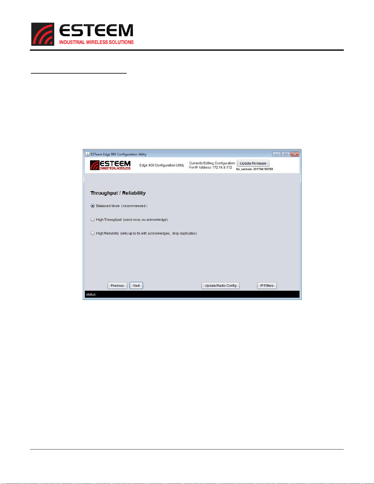
The Edge 900 will either be configured as the Master Bridge or the Remote Bridge. Every network will consist of a single
Master Bridge and one or more Remote Bridge radios. The first page of the Edge 900 Configuration Utility (Figure 11) will ask
if you are programming the Master or Remote Bridge.
Master Bridge Configuration
Verify the configuration page is set to Master Bridge (Figure 9) and select the following network optimization options. For
complete details on how to optimize the wireless network, please refer to the Network Optimization section later in this
user’s manual.
Figure 11: Step 1 –Master Bridge
Enable Multicast IP –This option will allow multicast traffic from IP addresses starting with 224.X.X.X or 239.X.X.X to pass
over the wireless bridge. To remove multicast traffic from the wireless network, uncheck this box.
NOTE: All network optimization settings are controlled from the Master Bridge. Once the Remote Bridge connects with the
Master, all optimization parameters will be downloaded to the remote sites automatically.
Enable Microsoft Netbios - This option will allow transfer of all Microsoft NetBIOS information to pass across the wireless
bridge link of Edge 900 radios. To remove NetBIOS traffic and greatly reduce the data load on Ethernet networks connected
to Windows based computers, uncheck this box.
Enable ARP Proxy –Address Resolution Protocol (ARP) traffic can be a significant amount of the Ethernet packets transferred
on a busy Ethernet network. An Ethernet ARP request is sent over the network to “find” an Ethernet device by its MAC and IP
address. Once determined, the IP data packet will then follow the ARP to the correct destination. In a static IP network,
where Ethernet devices and their programmed IP address do not frequently change location or programming, enabling the
ARP Proxy can greatly reduce the amount of Ethernet frames being sent over the wireless network. By default, the Edge 900
will pass all ARP traffic. To enable the ARP proxy, check the Enable ARP Proxy box.

Edge 900
User’s Manual
Revised: 21 June 2017 7 of 19
Remote Bridge Configuration
To configure the Edge 900 radio as a Remote Bridge, change the radial to Remote Bridge mode (Figure 12) on the first page.
Note that the network optimization options do not appear on the Remote Bridge as they will be set and sent over the
wireless network by the Master Bridge.
The first page is the only difference in configuration from the Master Bridge and the Remote Bridge. All other configuration
pages will be identical. Press the Next Button to continue.
Step 2 –Serial Port Configuration
Step two will set the data rate for the serial port on the Edge 900 (Figure 13). Configure to match the connected serial device
or skip to step 3 if only using the Ethernet interface. Press the Next button to proceed.
Figure 12: Step 1 –Remote Bridge Configuration
Figure 13: Step 2 –Serial Data Port Configuration

Edge 900
User’s Manual
Revised: 21 June 2017 8 of 19
Step 3 –Throughput and Reliability
Step three will set the option for how the Ethernet or Serial data will be processed by the wireless network. The default
setting is for an even balance between data throughput and number of RF packet retries, Balanced Mode, which is
recommended for most applications. If the data rate and response time is the highest priority, select High Throughput. High
throughput will send the data only once with no acknowledgements letting the application or protocol do the retries. Setting
the RF network for High Reliability will prioritize data verification as the expense of throughput. Once selected, press the
Next button to proceed.
Figure 14: Step 3 –Throughput and Reliability

Edge 900
User’s Manual
Revised: 21 June 2017 9 of 19
Step 4 –Encryption and Network Identification
The unique identification for an Edge 900 network is the AES-256 pass phrase (Figure 15). A unique pass phrase must be
entered to finish the configuration of the radio. This pass phrase must be between 4 and 64 characters long and MUST be
identical on all Edge 900 radios in the same network. This passphrase not only sets the encryption key, but also determines
the Edge 900’s hopping pattern. Select “Remember Pass Phrase”to have the utility automatically enter the pass phrase
when programming the next radio in the network. Select “Show Pass Phrase” to view the exact entry on the screen instead
of the asterisks. Enter the network pass phrase and press the “Update Radio Config”button. Enter the pass phrase a second
time and Figure 16 will be displayed to confirm the configuration has been accepted and the Edge 900 Configuration Utility
will close.
Note: The pass phrase will need to be entered in the utility to make programming changes are made after the initial
configuration. Keep the pass phrase well documented as there is no “back door” to the configuration.
Figure 15: Step 4 –Encryption and Network Identification
Figure 16: Configuration Accepted Message

Edge 900
User’s Manual
Revised: 21 June 2017 10 of 19
Testing and Troubleshooting
Updating Firmware
The firmware version for the Edge 900 is
imbedded in the Configuration Utility program.
The firmware version in the utility is listed
below the Update Firmware version button in
the upper right-hand corner (Figure 17). To
update the firmware version, press the “Update
Firmware” button. If the Edge 900 has the
current firmware version a message will be
displayed indicating the radio is up to date, if
not the update procedure will begin. Wait for
the firmware utility to update before
proceeding.
CAUTION: Do not remove power or reset the
Edge 900 during a firmware update.
Measuring Receive Signal Strength (RSSI)
The receive signal strength (RSSI) for all Edge 900 radios in the network will be displayed is the SSID field of the Discovery
Utility (Figure 18). This information will be displayed and updated every time the “Discover EST Radios” button is pressed.
The RSSI will display if you are connected to either the Master Bridge or Remote Bridge in the network.
The minimum receive signal strength to make a radio connection is -97dBm, but will vary based upon location, terrain and
other 900 MHz transmitters in the area. Through testing, most wireless networks with a signal strength greater than -85dBm
should operate reliably.
If measuring the RSSI from a Remote Bridge location and the Discovery Utility is showing “RSSI (No Sync)” in the SSID column,
the Remote Bridge is not receiving a radio signal from the Master Bridge or the Pass Phrase is different in the two radios.
Testing Ethernet Data Links
Figure 17: Updating Firmware
Figure 18: Receive Signal Strength Measurement

Edge 900
User’s Manual
Revised: 21 June 2017 11 of 19
The easiest method for testing the efficiency of data flow between the Edge 900 radios is to conduct a Ping test to the
opposite radio’s IP address. An Ethernet Ping utility is available in most TCP/IP computer’s operating system and is entered at
the command prompt (Figure 19). See operating system documentation or IT support for further detail.
Status Light
The status light on the front of the Edge 900 (Figure 5) has three states:
Off = No radio activity
Red = Transmitting radio packet
Green = Received radio packet
The Master Bridge sends out frequency hopping changes at a rate of 75 packets per second, so it will be mostly Red when
sending synchronization packets and the remotes will appear mostly Green. Alternating Green and Red lights indicates bi-
directional data is being sent across the wireless network.
What can I do if the Edge 900 has no connection or poor communication?
The following suggestions should cover most problems encountered but can never cover them all. If further problems are
experienced or more detail is required, please contact ESTeem support at 509-735-9092 or [email protected].
Measure and Increase Receive Signal Strength –Using the above information, review the current receive signal strength in
the wireless network. If the signal strengths are low, consider increasing the antenna height or change antenna type to
increase the antenna gain. Every wireless system is unique and the amount of required receive signal strength will vary
greatly based upon location, environment and other 900 MHz transmitters in the area. Through our testing we have found
most application with a receive signals strength greater than -85dBm should provide reliable communication.
Verify Line of Sight (LOS) –Verify there is an unobstructed line of sight between the antennas. Anything between the two
antennas such as trees, buildings or hills will cause a loss in the radio signal.
Change Pass Phrase –The Edge 900’s hopping pattern is determined by the network’s pass phrase. Changing the pass phrase
will allow the radio to operate on different frequencies in the 900 MHz spectrum and may improve communication. Is highly
recommended that if two Edge 900 networks are operating in the same geographical area, each use a unique pass phrase.
Figure 19: Ping Test Example

Edge 900
User’s Manual
Revised: 21 June 2017 12 of 19
Data Overload –If the Edge 900 network has good RSSI and operates reliably without adding the Ethernet devices to the
network, it is most likely being overrun with Ethernet network traffic. The Network Optimization section of this manual will
help to configure the wireless network to operate in high data traffic conditions.
Network Optimization
The most common problem experienced using a wireless network is data overload. The Ethernet network attempts to use
more bandwidth than the wireless network has available. The Edge 900 has a maximum RF data rate of 1 Mbps that must be
shared between multiple remote locations. The limited bandwidth available requires that the radio incorporate multiple tools
to mitigate the data overflow and optimize the wireless network for different Ethernet network requirements.
Throughput and Reliability Configuration
The Edge 900 allows the user to select how the Ethernet or Serial data will be processed by the wireless network.
Balanced Mode –This default configuration will provide an even balance between data throughput and number of RF packet
retries. This setting is recommended for most applications and will provide multiple remote sites equal access to the wireless
network.
High Throughput - If the data rate and response time is the highest priority, select High Throughput. High throughput will send
the data only once with no acknowledgements letting the application or protocol do the retries.
High Reliability - Setting the RF network for High Reliability will prioritize data verification at the expense of throughput. The
radio will wait for an acknowledgement that the data was received through the remote radio. It will attempt to resend the
packet multiple times if it does not receive this acknowledgement.
Limiting Ethernet Data Traffic
By default, the Edge 900 is configured as a wireless bridge device that will attempt to pass all Ethernet traffic received across
the wireless network. If the Edge 900 radios are connected to a busy office or plant network, it is very easy to overload the
limited bandwidth of the radio. The following tools help restrict the most common types of Ethernet network management
data packets sent over an office or plant network that can easily overload the wireless network:
Enable/Disable Multicast IP –This option will allow the user to select if multicast traffic (from IP addresses starting with
224.X.X.X or 239.X.X.X) to pass over the wireless bridge. Some industrial Ethernet devices communicate using multicast
traffic and can easily overload the wireless network. To remove multicast traffic from the wireless network, uncheck the
“Enable Multicast IP” box in the Master Bridge configuration. The Remote Bridge will receive this configuration setting from
the Master Bridge and does not require any other settings.
Enable Microsoft Netbios - This option will allow transfer of all Microsoft NetBIOS information to pass across the wireless
bridge link of Edge 900 radios. This Microsoft Windows based computer management frames are generally not required in
most TCP/IP based networks and only unnecessarily take up wireless bandwidth. To remove NetBIOS traffic and greatly reduce
the data load on Ethernet networks connected to Windows based computers, uncheck this box when configuring the Master
Bridge.
ARP Proxy
Address Resolution Protocol (ARP) traffic can be a significant amount of the Ethernet packets transferred on a busy Ethernet
network. An Ethernet ARP request is sent over the network to “find” an Ethernet device by its MAC and IP address. Once
determined, the IP data packet will then follow the ARP to the correct destination. Enabling the ARP Proxy can greatly reduce
the amount of Ethernet frames being sent over the wireless network by “answering” the ARP request locally from the Edge
900 itself. In a busy Ethernet network, enabling the ARP proxy can reduce the wireless network traffic by half.
If using the ARP proxy, be aware that the Edge 900 will always send the first occurrence of each ARP packet and then build an
internal data table of where the Ethernet device is in the network. This table will be updated any time an unknown ARP
request is sent to the radio but if a remote Ethernet device is changed (changing the correlation between the Ethernet MAC
address and IP address) or an IP address is changed in the network the Edge 900 will not automatically update the internal
ARP table. In a static IP network, where Ethernet devices and their programmed IP address do not frequently change location

Edge 900
User’s Manual
Revised: 21 June 2017 13 of 19
or programming, this is generally not an issue. If the ARP Proxy is being used and a remote device or IP address is changed,
simply uncheck the ARP proxy button in the configuration and save the configuration. Once the new device or address is
then learned by the Master Bridge, reopen the configuration utility and reenable the ARP Proxy. The ARP table is always
saved in the Edge 900 and will not require re-learning all sites in the Ethernet network.
By default, the Edge 900 will pass all ARP traffic. To enable the ARP proxy, check the “Enable ARP Proxy”box when
configuring the Master Bridge. Enabling the ARP Proxy in the Master Bridge will also enable this feature in all the Remote
Bridges.
IP Filter
The highest level of wireless Ethernet network optimization is done through limiting which specific IP addresses can be sent
over the wireless network. This IP filtering is available in both the Master Bridge and Remote Bridge configurations of the
Edge 900 and can be accessed by pressing the “IP Filters”button on any of the configuration pages (Figure 20).
Figure 20: Selecting IP Filtering

Edge 900
User’s Manual
Revised: 21 June 2017 14 of 19
Once “Edit IP filters” is selected, the IP filter editor (Figure 21) will be displayed.
The default configuration for the filter is to allow all IP addresses to use the wireless network (Figure 19). The IP filter limits
the outbound IP address from each Edge 900 in the network. For example, the destination IP address (or address range) the
Edge 900 receives into the Ethernet port will be tested against the filter to see if Ethernet packet will be sent over the
wireless network. To limit the outbound IP addresses, uncheck the “Allow All” box and check the “Show Empty Entries” to
begin editing (Figure 22).
The IP filter uses standard IP address entries as would be used in configuring a router. The filter looks at the IP address and
subnet entered to determine if the destination is allowed in the network. The filter can be configured to filter to a single IP
address or an address range by changing the subnet entry. If a specific range of address is required, it is highly recommended
to use a subnet calculator (multiple free versions available on the internet) or consult with an IP administrator. The following
examples are the most common type of entries.
Single IP Address Entry = IP: <IP Address –XXX.XXX.XXX.XXX> Net Mask: 255.255.255.255
IP Address Range Entry = IP: <IP Address for Subnet –XXX.XXX.XXX.0> Net Mask: 255.255.255.0
Once all entries are completed, press the “Update Filter Configuration” to save the entries. Figure 21 shows a full filter.
Figure 21: IP Filter Editor
Figure 22: Editing IP Filter

Edge 900
User’s Manual
Revised: 21 June 2017 15 of 19
If you uncheck the “Show Empty Entries” button after updating the IP filter, only the active IP elements will be shown. In
Figure 23 below, two IP subnet ranges and three single IP addresses were entered in the filter. The Edge 900 with the saved
filter would only send Ethernet IP packets over the wireless link to the following IP addresses:
Entry 1 (IP Subnet filter) –IP addresses from 172.16.8.1 through 172.16.8.254
Entry 2 (IP Subnet filter) –IP addresses from 172.16.50.1 through 172.16.50.254
Entry 3 (Single IP filter) –IP address 172.16.58.125
Entry 4 (Single IP filter) –IP address 172.16.58.128
Entry 5 (Single IP filter) –IP address 172.16.58.200
NOTE: To ping the IP address of a remote ESTeem Edge 900 it will require its own IP address be entered in the filter also.
Figure 23: IP Filter Entry Examples

Edge 900
User’s Manual
Revised: 21 June 2017 16 of 19
Information to Users
The equipment has been tested and found to comply with the limits for both the FCC Class B digital device (pursuant to Part 15
of the FCC rules) and Industry Canada (IC) CAN ICES-3 (B)/NMB-3(B).
FCC Statement
Operation is subject to the following two conditions: (1) This device may not cause harmful interference, and (2) this device
must accept any interference received, including interference that may cause undesired operation.
Caution: Changes or modifications to this equipment not expressly approved by ESTeem Wireless Modems for compliance
could void the user's authority to operate the equipment.
IC Statement
“This device complies with Industry Canada licence-exempt RSS standard(s). Operation is subject to the following two
conditions: (1) this device may not cause interference, and (2) this device must accept any interference, including
interference that may cause undesired operation of the device.”
“Cet appareil est conforme avec Industrie Canada exempts de licence standard RSS (s). Son fonctionnement est soumis aux
deux conditions suivantes: (1) cet appareil ne doit pas provoquer d'interférences et (2) cet appareil doit accepter toute
interférence, y compris celles pouvant causer un mauvais fonctionnement de l'appareil.”
Emissions Information
Edge 900 MHz (Model 217ES)
HVIN: 217ES
Frequency Hopping/DTS Spread Spectrum Device
(USA) FCC ID: ENPEDG217ES
(Canada) IC No: 2163A-217ES

Edge 900
User’s Manual
Revised: 21 June 2017 17 of 19
Edge 900 MHz Antenna and Cable Configurations
ESTeem offers different types of antennas for both indoor and outdoor configurations. This device has been designed to
operate with the antennas listed below, and having a maximum gain of 7 dB. Antennas not included in this list or having a
gain greater than 7 dB are strictly prohibited for use with this device. The required antenna impedance is 50 ohms.
This radio transmitter ESTeem Edge 900 MHz (HVIN: 217ES) has been approved by Industry Canada to operate with the antenna
types listed below with the maximum permissible gain and required antenna impedance for each antenna type indicated.
Antenna types not included in this list, having a gain greater than the maximum gain indicated for that type, are strictly
prohibited for use with this device.
Le present emetteur radio ESTeem HVIN: 216AD a ete approuve par Industrie Canada pour fonctionner avec les types d'antenne
enumeres ci-dessous et ayant un gain admissible maximal et l'impedance requise pour chaque type d'antenne. Les types
d'antenne non inclus dans cette liste, ou dont le gain est superieur au gain maximal indique, sont strictement interdits pour
l'exploitation de l'emetteur.
Warning: Only the tested cable lengths and antennas provided by EST meet the FCC and DOC maximum peak output
power requirements. Any other combination of antennas or coax cables is not authorized. To reduce potential radio
interference to other users, the antenna type and its gain should be so chosen that the equivalent isotropically radiated
power (e.i.r.p.) is not more than that permitted for successful communication.
Part Number: AA20DMEs
Omni-directional direct mount antenna, 2 dBi gain.
Indoor and outdoor applications.
There must be a minimum separation distance of 23
cm. from the antenna to the user. See Warnings.
Part Number: AA20Es900
Omni-directional external pole mount antenna, 7 dBi
gain with 3-ft. integral feedline and connector.
Outdoor applications.
There must be a minimum separation distance of
23cm. from the antenna to the user. See Warnings.
Part Number: AA203Es900
Directional pole mount antenna, 7 dBi gain with 3-ft.
integral feedline and connector.
Point to point and point to multi-point outdoor
applications.
There must be a minimum separation distance of 23
cm. from the antenna to the user. See Warnings.
Warnings:
Only pre-made coax cables from the factory used in
conjunction with either the AA20Es900 omni-directional and
AA203Es900 directional antennas meet all FCC Section
15.247(b) EIRP maximum power requirements.
Transmit/Receive
Antenna Port

Edge 900
User’s Manual
Revised: 21 June 2017 18 of 19
Edge 900 Specifications
Transmiter/Receiver
Frequencyof Operation 902-928 MHz
RF Data Rate 1 Mbps
TxOutput Power (Software Selectable) 24dBm
TxOutput Impedance 50 ohms
RxSensitivity -97 dBm
FCC Type Acceptance ENPEDG217ES
IndustryCanada Type Acceptance 2163A-217ES
LED Indicators Power (On/Off) - Carrier Detect (On/Off) - Transmitter (On/Off) - Reveiver (On/Off)
Power Requirements
Receive 160mA@ 12 VDC
Transmit 700mA@ 12 VDC
PoE Power Supply (IEEE 802.3at,30 watts) (opt)
External Power Input 10 to 16 VDC @ 1A
Input/Output Connectors
Ethernet Port 1 (10/100/1000) RJ-45 Female
RS-232C Comm Port (2,400 to 115.2 K baud) RJ-45 Female
Antenna Input/Outputs TNC Reverse Female
External DC Input Power Mini-Combicon, 3 pin female
Case
Temperature Range -30° to +60° C
Humidity 95% Non-condensing
Dimensions 1.9 in. H x6.7 in. W x6.2 in. L
Weight 1.25 lbs.
Product Warranty 1 Year
Other
Outdoor Pole Mt. Kit AA195PM(opt)
PoE Power Supply AA175.2 (opt)
ESTeem Edge 900 Specifications
Other manuals for Edge 900
3
Table of contents
Other ESTeem Modem manuals