Esu 53900 Setup guide

Profi-Prüfstand (Decoder Tester)
P Zum schnellen Prüfen von Decodern ohne vorherigen Lokeinbau
For testing decoders before they are installed into a loco
P Mit allen gängigen Schnittstellen für einfachsten Anschluss
With all common interfaces for easy connection
P Mit hochwertigem Glockenankermotor und Lautsprecher
With high precision coreless motor and speaker
P Einfacher Anschluss an die Digitalzentrale oder ESU LokProgrammer
Easy connection to your digital command station or the ESU LokProgrammer
P Mit Anschluß für Großspurdecoder Erweiterung
With Extension port for large scale decoder extension board
www.esu.eu
ESU GmbH & Co. KG
Edisonallee 29
D - 89231 Neu-Ulm
GERMANY
ESU LLC
23 Howard Street
US-17754 Montoursville PA
USA
WARNING: This product contains chemicals which are known to the state of California
to cause cancer, birth defects or other reproductive harm.
53900 Pro-Prüfstand (Decoder Tester)
NEM651, NEM652, 21MTC,
PluX, Next18, LED-Monitor
20mm Lautsprecher 4AOEGOP*fdjaac+
MADE IN CHINA
Dieses Produkt ist kein Spielzeug. Nicht geeignet für Kinder unter 14 Jahren.
This product is not a toy. Not recommended for children under 14 years of age.
ESU P/N 04915-16803

Warnhinweise
•Der Profi-Prüfstand ist ausschließlich zum Testen von Decodern für elektrische Modelllokomotiven vorgesehen.
Er darf nur mit den in dieser Anleitung beschriebenen Komponenten betrieben werden.
•AlleAnschlussarbeitendürfennurbeiabgeschalteterBetriebsspannungdurchgeführtwerden.
•HaltenSiesichbeimAnschlussvonDecodernamProfi-PrüfstandandiehiergezeigtenPrinzipien.
•VorNässe,StoßundDruckbelastungenschützen.
Allgemeine Eigenschaften
Der Profi-Prüfstand ist zum Testen oder Programmieren von Digitaldecodern mit Digitalzentralen oder dem ESU
LokProgrammer vorgesehen. Hierzu simuliert der Profi-Prüfstand alle Elemente einer Lok. Es sind alle gängigen
Schnittstellen für die Spurweiten N bis H0 vorhanden.
Anschluss des Decoders
AufderPlatineIhresPro-PrüfstandessinddieeinzelnenElementebeschriftet.BenutzenSiehierzudiepassende
Schnittstelle.SteckenSienurjeweilseinenDecoderaufdenPro-Prüfstandauf.BeachtenSieAbb.1.
Haben Sie einen Decoder ganz ohne Digitalschnittstelle, so können Sie die Litzen auch einzeln an die Schraub-
klemmeanschliessen.BeachtenSiebittedieKabelfarben,welchefürDCCundMärklinunterschiedlichsind.Die
Tabelle Abb. 3 gibt Auskunft.
Anschluss an den LokProgrammer oder Digitalzentrale
Der Profi-Prüfstand muss mit dem Programmiergleisausgang Ihrer Digitalzentrale oder dem LokProgrammer
verbunden werden. Hierzu wird eine zweipolige, abnehmbare Reihenklemme mitgeliefert, die mittels eines dop-
pelseitigen Klebebands unterhalb des Prüfstandes befestigt ist (Transportsicherung). Entfernen Sie die Klemme
und stecken Sie diese wie in der Abbildung 4 auf der Rückseite gezeigt, in den Prüfstand ein. Stellen Sie danach
die Kabelverbindung her. Wenn Spannung von der Digitalzentrale (bzw. LokProgrammer) anliegt, sollten beide
mit „TRACK“ beschrifteten LEDs leuchten bzw. unregelmäßig flackern.
Motor Richtungs LEDs
Neben dem Glockenankermotor befinden sich zwei LEDs. Sobald sich der Motor dreht, sollte eine der beiden LEDs
aufleuchten oder flackern, um die Drehrichtung des Motors anzuzeigen.
Lautsprecher
Möchten Sie einen LokSound V3.5 Decoder testen, stellen Sie den Schiebeschalter bitte auf 100 Ohm. Für
LokSoundV4oderalleanderenDecoder,bitteauf16Ohmstellen.MöchtenSieeinenDecodertesten,andem
der Lautsprecher direkt am Decoder angelötet ist, schalten Sie den am Prüfstand verbauten Lautsprecher bitte
aus(Stellung„Off“).
Profi-Prüfstand Extension
Möchten Sie auch ESU Decoder für die Spuren 0 oder G testen, können Sie die separat erhältliche Profi-Prüfstand
Extension (ESU Art. Nr. 53901) direkt an den Profi-Prüfstand anstecken. Hierzu dient ein separater Stecker, wie
in Abb. 2 gezeigt.
Die Pins 1,2,19,20,21
& 22 bleiben frei.
Pin 1,2,19,20,21 and 22
remain free.
MTC-Stiftleistenbuchse
zeigt nach oben!
MTC plug connector
must show upwards!
Next18-
Buchse
zeigt nach
unten!
Next18 must
show down-
wards!
Abb. 1: Profi-Prüfstand mit verschiedenen Schnittstellen // Decoder testing showing different interfaces

Abb. 3: Farbschema der Decoderkabel (DCC / Märklin®) // Wiring code for decoder wires (DCC / Märklin®)
21MTC PluX Next18 Hinweise (Notes) Name Märklin DCC
22 12 1, 18 TRACK1 rot schwarz
red black
21 14 9, 10 TRACK2 braun rot
brown red
19 8 2 MOTOR1 blau orange
blue orange
18 10 11 MOTOR2 grün grau
green gray
16 96 +24V(U+,pos.Terminal) orange blau
orange blue
7 13 17 REARLIGHT gelb gelb
yellow yellow
8 7 8 FRONTLIGHT grau weiß
gray white
15 16 3OutputAUX1 braun/rot grün
brown/red green
14 18 12 OutputAUX2 braun/grün violett
brown/green purple
13 2 4 Logikausgang an 21MTC OutputAUX3 braun/gelb -
logic level on 21MTC brown/yellow -
4 19 13 Logikausgang an 21MTC OutputAUX4 braun/weiß -
logic level on 21MTC brown/white -
17 20 - Logikausgang an 21MTC OutputAUX5 braun/gelb -
logic level on 21MTC brown/yellow -
3 21 - Logikausgang an 21MTC OutputAUX6 braun/weiß -
logic level on 21MTC brown/white -
9
10
15
17
16
7
Speaker 1
Speaker 2
Abb. 2: Profi-Prüfstand und Profi-Prüfstand Extension // Profi tester and Profitester Extension module
Important warnings
•Thedecodertesterisexclusivelyintendedfortestingdecodersofmodeltrainlayouts.Itmayonlybeoperated
with the components listed here. Any other use is not permitted.
•Anywiringhastobecarriedoutwhilepowerisdisconnected.
•Adheretothewiringprinciplesasoutlinedhereforwiringanydecoderstothedecodertester.
•Keepdryandprotectitfrommechanicalshocks.
Configuration
The decoder tester is designed for testing or programming of decoders in combination with your digital command
station or ESU LokProgrammer before these are installed into a loco. Therefore, the decoder tester simulates all
needed elements usually seen in a locomotive. The decoder tester is equipped with all common interfaces.
Decoder connection
On the decoder tester, all items are labelled for your reference. Please select the appropriate interface first. Connect
one decoder to the tester at a time only. See figure 1 for details.
If you own a decoder without interface, you can connect the single wires to the screw terminal. Please note the
colour code that is different for DCC or Märklin. Figure 3 shows the details.
Connection to the LokProgrammer or the command station
The decoder tester has to be connected to the programming track output of your command station or the Lok-
Programmer. We supply a 2-pin, removable plug, that is first fixed below the decoder tester using a small piece of
tape for transport reasons. Remove the plug and connect it to the decoder tester as shown in figure 4. Then, add
two wires from the tester to the command station / LokProgrammer. If power is applied to the command station‘s
orLokProgrammer‘soutput,theLEDlabelled„TRACK“shouldlit.
Motor Direction LEDs
Next to the motor, you can find two LEDs. Based on the direction of travel, one of these should lit when the
motor is moving.
Speaker
IfyouwouldliketotestanoldLokSoundV3.5decoder,settheswitchto„100Ohms“.Otherwise,pickthe„16
Ohms“setting.Ifyoudon‘tlikethespeakeroutput,justswitchittoOFFposition.
Decoder tester Extension
If you want also test ESU Decoders for gauge 0 or G, you can connect the Decoder Tester Extension (ESU Item
number 53901) to your tester. Figure 2 shows how to connect it.

PluX22-Schnittstelle
PluX22 interface
LED-Anzeige für
Funktionsausgänge
LED‘s for function outputs
Schraubklemmen zum
Anschluss an
Digitalzentralen
oder LokProgrammer
Screw terminals for
connection
to command station or
LokProgrammer
8-poligeNEM652Schnittstelle
8-pin NMRA socket
6-poligeNEM651Schnittstelle
6-pinNMRAsocket
Einzelklemmen für Decoder ohne Schnittstelle
Single terminals for decoders without interface
21MTC-Schnittstelle
21MTC interface
20mmLautsprecher16Ohm
20mmspeaker16Ohms
Glockenankermotor mit Schwungmasse
coreless motor with flywheel
Lautsprecherumschaltung
Off/100Ohm/16Ohm
Loud speaker change over
Off/100Ohms/16Ohms
Element
Item
Platinenaufdruck
PCB print
Erklärung
Description
Lautsprecher - Lautsprecher 20mm, 0.5Watt, zum Test von LokSound Decodern. Anschluss mit Klemmleiste,
21MTC,PluX,oderNext18-Schnittstelle,Schiebeschalter zum Umschaltenzwischen100und
16Ohm.Decoderanleitungbeachten!
Loud speaker - Loud speaker 20mm, 0,5W, to test LokSound decoders. Connection using the terminal block,
21MTC,PluX-orNext18-connector,slidingswitchtoswitchbetween100and16Ohms.Pleasestick
to decoder manual!
Motor - Glockenankermotor mit Schwungmasse angeschlossen an Motorausgang des Decoders.
Motor - Coreless motor with flywheel connected to motor output of decoder.
LED Display FRONTLIGHT Anzeige für Licht vorne. Leuchtet auf, wenn am Decoder Licht vorne aktiviert wird.
LED display Indicator for head lights. Enabled, if head lights are activated on the decoder.
LED Display REARLIGHT Anzeige für Licht hinten. Leuchtet auf, wenn am Decoder Licht hinten aktiviert wird.
LED display Indicator for rear lights. Enabled, if rear lights are activated on the decoder.
LED Display AUX1-AUX7 AnzeigefürFunktionsausgangAUX1-7.Leuchtetauf,wennamDecoderAUX1-7aktiviert
wird. AUX3, AUX4 sind erreichbar über 21MTC, PluX22, Next18. AUX5 - AUX6 über
21MTC,PluX22
LED display Indicator for function output AUX1-7. Enabled, if AUX1-7 is activated on the decoder. AUX3, AUX4
areavailableonthe21MTC,PluX22andNext18connector,AUX5,AUX6on21MTC,PluX22,AUX7
on PluX22 only
Anschluss TRACK IN Reihenklemme zum Anschluss von Digitalsystemen oder dem ESU Digitalzentrale LokPro-
grammeranDigitalsysteme.DiePolungistegal.BeiaktivierterGleisspannungleuchtendie
zugehörigenLEDs.BitteNIEMALSbeideEingängegleichzeitigverwenden!
Connection to
command station
Terminal block to connect to the digital command station or ESU LokProgrammer. The polarity does not
matter. When the command station‘s track power is on, the two corresponding LEDs will light. Please
use either the screw terminal OR the alternative connector. Never use both at the same time!
21MTC 21MTC Anschlussfür21MTCDecoder.BittebeimAufsteckenaufkorrektePolungachten!
21MTC Connection for decoders using 21MTC interface. Please carefully check the decoder polarity prior
to connection!
PluX-Schnittstelle AnschlussfürPluX-Decoder.GeeignetfürPluX12,PluX16undPluX22.BittebeimAufstecken
aufkorrektePolungunddenIndex-Pinachten!
PluX interface ConnectionforPluXdecoders.FitsPluX12,PluX16andPluX22decoders.Pleasecarefullycheckthe
decoder polarity and the index pin location prior to connection!
Next18-Schnittstelle AnschlussfürNext18-Decoder.BittebeimAufsteckenaufkorrektePolungachten!
Next18 interface Connection for Next18 decoders. Please carefully check the decoder polarity prior to connection!
Schraubklemme Testanschluss für Decoder ohne Schnittstelle. Farbschema für DCC und Märklin siehe
Abb. 3.
Wichtig:NureinenDecoderanschließen.NiemalsexterneSpannunghiereinspeisen!
Screw terminal To test decoders without any interface plug (single wires). Please carefully check the wiring code
(see Figure 3).
Important: Please connect ONE decoder only. Never feed in external voltage to the tester here!
6-polNEM651 NEM651,yellow Testanschlussfür6-Pol-Decoder. Achten Sie beim Anschluss darauf, dasssichdas gelbe
Kabel auf der Schnittstelle Seite der Markierung („yellow“) befindet.
6pinDCC Connection for 6-pin decoders. Please note that the yellow wire of the plug matches the „yellow“
mark on the PCB.
8-polNEM652 NEM652,* Testanschlussfür8-Pol-Decoder.BeimAnschlussmusssichdasroteKabelaufderSeitemit
derMarkierung(„*“)benden.AUX2mussanderKlemmleistekontaktiertwerden.
8 pin DCC Connectionfor8-pindecoders.Pleasenotethattheorangewireoftheplugmatchesthe„*“mark
on the PCB.
Next18-Schnittstelle
Next18 interface
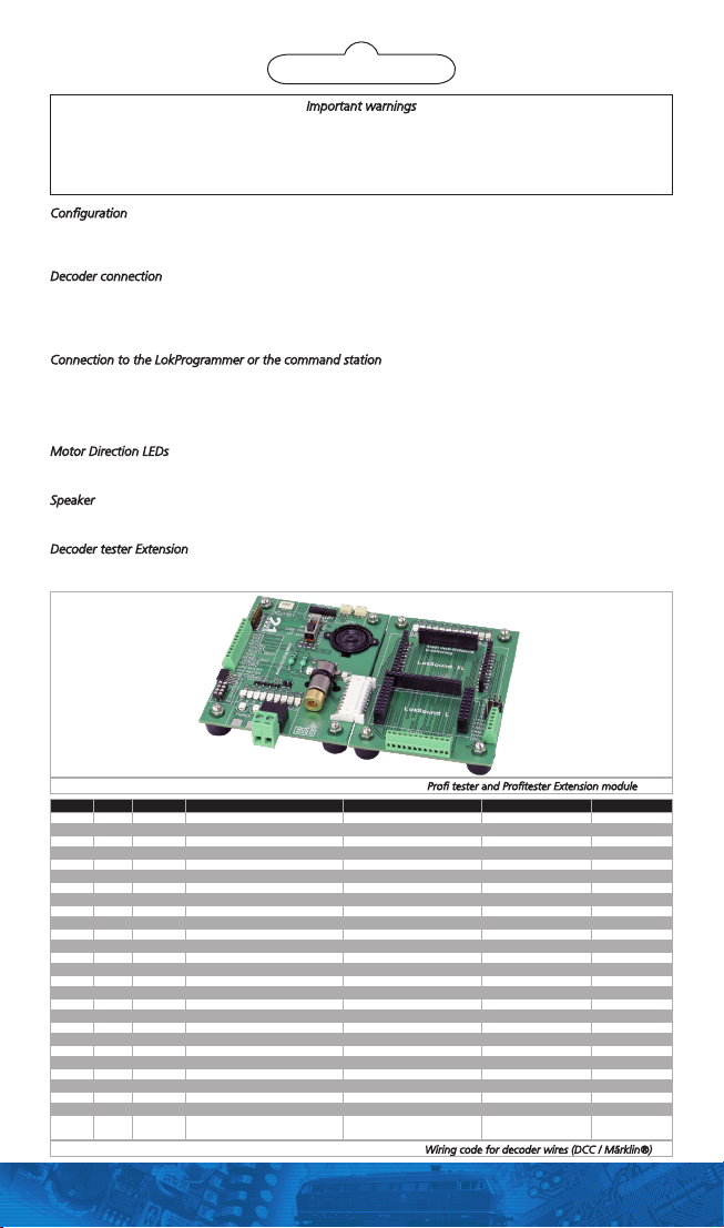
Anschluss für ProfiPrüfstand Extenion
Connector for decoder tester extension module
Abb. 4: Verschiedene Anschlüsse am Profi-Prüfstand // Different types for connenction
Table of contents
Languages: