ETAS ES4455.1 User manual

ES4455.1 Load Board
User’s Guide

2
Copyright
The data in this document may not be altered or amended without special
notification from ETAS GmbH. ETAS GmbH undertakes no further obligation in
relation to this document. The software described in it can only be used if the
customer is in possession of a general license agreement or single license.
Using and copying is only allowed in concurrence with the specifications
stipulated in the contract.
Under no circumstances may any part of this document be copied, repro-
duced, transmitted, stored in a retrieval system or translated into another
language without the express written permission of ETAS GmbH.
© Copyright 2008 ETAS GmbH, Stuttgart
The names and designations used in this document are trademarks or brands
belonging to the respective owners.
R1.0.1 EN - 09.2008 TTN F 00K 106 170

Contents 3
Contents
1Introduction . . . . . . . . . . . . . . . . . . . . . . . . . . . . . . . . . . . . . . . . . . . . . . . . . . . . . 5
1.1 Applications . . . . . . . . . . . . . . . . . . . . . . . . . . . . . . . . . . . . . . . . . . . . . . . 6
1.2 Features . . . . . . . . . . . . . . . . . . . . . . . . . . . . . . . . . . . . . . . . . . . . . . . . . . 6
1.3 Load Modules . . . . . . . . . . . . . . . . . . . . . . . . . . . . . . . . . . . . . . . . . . . . . . 8
1.4 Taking the Product Back and Recycling . . . . . . . . . . . . . . . . . . . . . . . . . . . 9
2Hardware . . . . . . . . . . . . . . . . . . . . . . . . . . . . . . . . . . . . . . . . . . . . . . . . . . . . . . 11
2.1 Numbering the Loads on an ES4455.1 Load Board . . . . . . . . . . . . . . . . . 11
2.1.1 Load Signals to the Backplane . . . . . . . . . . . . . . . . . . . . . . . . . 12
2.1.2 Connecting Loads and Measuring the Signals. . . . . . . . . . . . . . 12
2.2 Current Transducers . . . . . . . . . . . . . . . . . . . . . . . . . . . . . . . . . . . . . . . . 13
2.2.1 Configuring the Current Transducers . . . . . . . . . . . . . . . . . . . . 13
2.2.2 Calibration . . . . . . . . . . . . . . . . . . . . . . . . . . . . . . . . . . . . . . . . 15
2.2.3 Overcurrent Protection of the Measure Outputs . . . . . . . . . . . . 15
2.3 Digital Current Signals . . . . . . . . . . . . . . . . . . . . . . . . . . . . . . . . . . . . . . . 15
2.3.1 Configuring Current Measuring . . . . . . . . . . . . . . . . . . . . . . . . 16
2.3.2 LED Display. . . . . . . . . . . . . . . . . . . . . . . . . . . . . . . . . . . . . . . . 16
2.3.3 Acoustic Signals . . . . . . . . . . . . . . . . . . . . . . . . . . . . . . . . . . . . 16
2.4 Settings in LABCAR-RTC . . . . . . . . . . . . . . . . . . . . . . . . . . . . . . . . . . . . . 17

Contents4
3Pin Assignment and Display Elements . . . . . . . . . . . . . . . . . . . . . . . . . . . . . . . . . 19
3.1 “Threshold Calibration Connection” Connector . . . . . . . . . . . . . . . . . . . 19
3.2 LEDs for Status Display . . . . . . . . . . . . . . . . . . . . . . . . . . . . . . . . . . . . . . 20
4Accessories. . . . . . . . . . . . . . . . . . . . . . . . . . . . . . . . . . . . . . . . . . . . . . . . . . . . . 21
4.1 PB4451CR Piggyback for 2 RB CRS Injectors . . . . . . . . . . . . . . . . . . . . . . 21
4.2 PB4451GDI Piggyback for 2 RB GDI Injectors . . . . . . . . . . . . . . . . . . . . . . 22
5Technical Data . . . . . . . . . . . . . . . . . . . . . . . . . . . . . . . . . . . . . . . . . . . . . . . . . . 23
6ETAS Contact Addresses . . . . . . . . . . . . . . . . . . . . . . . . . . . . . . . . . . . . . . . . . . . 25
Index . . . . . . . . . . . . . . . . . . . . . . . . . . . . . . . . . . . . . . . . . . . . . . . . . . . . . . . . . 27

Introduction 5
1 Introduction
This User’s Guide describes the ES4455.1 Load Board. It consists of the
following chapters:
• "Introduction" on page 5
This chapter – here you will find general information on the ES4455.1
Load Board.
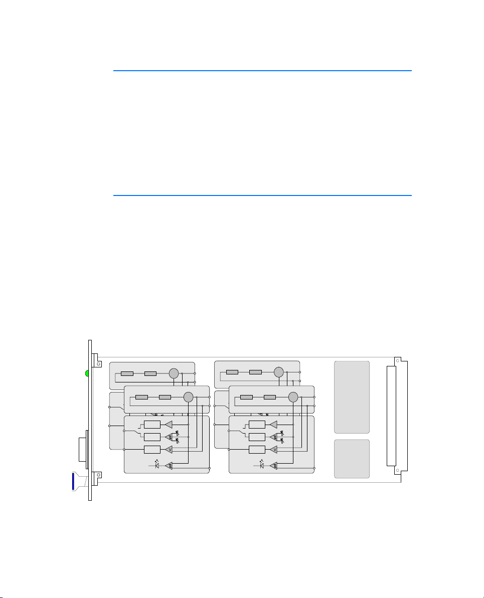
• "Hardware" on page 11
This chapter describes the individual function units of the ES4455.1
Load Board in more detail.
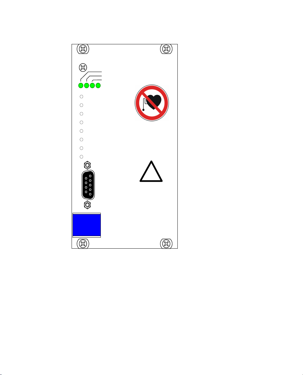
• Pin Assignment and Display Elements
This chapter contains a description of the pins and LEDs on the front
panel of the ES4455.1 Load Board.
• "Accessories" on page 21
This chapter describes the dummy loads available to date which are
assembled as piggybacks on the board of the ES4455.1 Load Board.
• "Technical Data" on page 23
This chapter contains the technical data of the ES4455.1 Load Board.
CAUTION!
Some components of the ES4455.1 Load Board may be damaged
or even destroyed by static discharge. Leave the board in its
transport package until you want to install it.
The ES4455.1 Load Board should only be taken from its package,
configured and installed at a working place that is protected
against static discharge.
WARNING!
The components, connectors and conductors of the ES4455.1
Load Board may carry dangerous voltages. These voltages may
even exist if the ES4455.1 is not installed in the ES4408.1 Load
Chassis or the ES4408.1 Load Chassis is powered off.
Make sure the ES4455.1 is protected against contact during
operation. Disconnect all connectors to the ES4455.1 before
removing the board.

Introduction6
1.1 Applications
The ES4455.1 Load Board is a carrier board for accommodating two modules
(each with two channels) for simulating high-current loads (to 90 V and to
20 A), such as injection loads.
In the ES4408.1 Load Chassis there are three 14 HP slots for accommodating
ES4455.1 Load Boards or pre-assembled variants (see "“Pre-Assembled
Solutions” with Integrated Load Modules" on page 8).
When fully assembled, the injection loads of a 12-cylinder engine can be
simulated.
1.2 Features
The ES4455.1 Load Board has the following features:
• 3 U plug-in board (14 HP, 3400 mm x 100 mm)
• Four channels for load simulations to 20 A
• Four galvanically isolated analog or digital channels for current
measuring
• Four galvanically isolated analog channels for voltage measuring
• To date, modules for the Bosch Common Rail System (two modules
each with two loads) and Bosch GDI (two modules each with two
loads) are available
Fig. 1-1 shows the block diagram of the ES4455.1 Load Board.
Fig. 1-1 Block Diagram of the ES4455.1 Load Board
PLD
EEPROM
Load 1
I
Output
Protection
Output
Protection
Output
Protection
DAC
I_Ana_Out
I_Dig_Out
V_Out
Load 2
I
Output
Protection
Output
Protection
Output
Protection
DAC
I_Ana_Out
I_Dig_Out
V_Out
Load 3
I
Output
Protection
Output
Protection
Output
Protection
DAC
I_Ana_Out
I_Dig_Out
V_Out
Load 4
I
Output
Protection
Output
Protection
Output
Protection
DAC
I_Ana_Out
I_Dig_Out
V_Out

Introduction 7
The following figure shows the front panel of the ES4455.1 Load Board.
Fig. 1-2 Front Panel of the ES4455.1 Load Board
The elements of the front panel are:
• The „Loadn“ LEDs indicating load current
• The LEDs which light up when the currents exceed a threshold set in
the (LABCAR-RTC) software
• The potentiometers for setting the lower and upper thresholds for
digitizing the output signal
• The “Threshold Calibration” connector at which the thresholds set
using the potentiometers are output
ETAS
ES4455.1
Load0
Load1
Load2
Load3
Threshold high Load 0
Threshold low Load 0
Threshold high Load 1
Threshold low Load 1
Threshold high Load 2
Threshold low Load 2
Threshold high Load 3
Threshold low Load 3
Threshold
calibration
connection
!

Introduction8
1.3 Load Modules
The following load modules are currently available for the ES4455.1 Load
Board:
• PB4451CR Piggyback for 2 RB CRS Injectors
Simulation for injectors of the Bosch Common Rail System
• PB4451GDI Piggyback for 2 RB GDI Injectors
Simulation for injectors of the Bosch HDEV GDI system
For more information on the modules, refer to the chapter "Accessories"
on page 21.
“Pre-Assembled Solutions” with Integrated Load Modules
The ES4455.1 Load Board can also be supplied as an assembled version with
these modules under the following names:
• ES4450.2 Load Board for 4 RB CRS Injectors
The ES4450.2 enables the simulation of four injectors of the Bosch
Common Rail System (CRS). It consists of the ES4455.1 Load Board and
two piggybacks of the type “PB4451CR Piggyback for 2 RB CRS
Injectors”.
• ES4451.3 Load Board for 4 RB GDI Injectors
The ES4451.3 enables the simulation of four injectors of the Bosch
gasoline direct injection system. It consists of the ES4455.1 Load Board
and two piggybacks of the type “PB4451GDI Piggyback for 2 RB GDI
Injectors”.
Order Data
Tab . 1 -1 Order Data for Load Modules and Pre-Assembled Solutions
Order Name Short Name Order Number
PB4451CR Piggyback for 2 RB CRS
Injectors
PB4451CR F-00K-106-323
PB4451GDI Piggyback for 2 RB GDI
Injectors
PB4451GDI F-00K-106-324
ES4450.2 Load Board for 4 RB CRS
Injectors
ES4450.2 F-00K-106-167
ES4451.3 Load Board for 4 RB GDI
Injectors
ES4451.3 F-00K-106-171

Introduction 9
1.4 Taking the Product Back and Recycling
The European Union has passed a directive called Waste Electrical and
Electronic Equipment, or WEEE for short, to ensure that systems are setup
throughout the EU for the collection, treating and recycling of electronic
waste.
This ensures that the devices are recycled in a resource-saving way representing
no danger to health or the environment.
Fig. 1-3 WEEE Symbol
The WEEE symbol on the product or its packaging shows that the product
must not be disposed of as residual garbage.
The user is obliged to collect the old devices separately and return them to the
WEEE take-back system for recycling.
The WEEE directive concerns all ETAS devices but not external cables or
batteries.
For more information on the ETAS GmbH Recycling Program, contact the ETAS
sales and service locations (see "ETAS Contact Addresses" on page 25).

Introduction10

Hardware 11
2 Hardware
This chapter describes the individual function units of the ES4455.1 Load
Board in more detail.
These are:
• "Numbering the Loads on an ES4455.1 Load Board" on page 11
– "Load Signals to the Backplane" on page 12
• "Current Transducers" on page 13
– "Configuring the Current Transducers" on page 13
– "Calibration" on page 15
– "Overcurrent Protection of the Measure Outputs" on page 15
• "Digital Current Signals" on page 15
– "Configuring Current Measuring" on page 16
– "LED Display" on page 16
– "Acoustic Signals" on page 16
• "Settings in LABCAR-RTC" on page 17
2.1 Numbering the Loads on an ES4455.1 Load Board
The following figure shows the power supply to the load modules via the
standoffs, the corresponding current transducers and the jumper strip for
configuring an analog/digital current signal (JP200).
Fig. 2-1 Names of the Load Connectors and Numbering of the Loads
(Component Side without Assembled Loads)
Load 1+
Load 1-
Load 4+
Load 4-
Load 2+
Load 2-
Load 3+
Load 3-
I/I
Load 2
I/I
Load 3
I/I
Load 1
I/I
Load 4
JP200

Hardware12
2.1.1 Load Signals to the Backplane
Slots 1 - 3 of the ES4408.1 Load Chassis are intended for the integration of the
injection loads (for more details, refer to the ES4408.1 Load Chassis) User’s
Guide. The supply of the signals from the backplane connectors of the
ES4408.1 Load Chassis is as follows:
Tab . 2 -1 Current Signals of the Backplane Connectors Slot 1...Slot 3
2.1.2 Connecting Loads and Measuring the Signals
The loads are connected via connectors on the rear of the ES4408.1 Load
Chassis - next to them are the connectors for the measure signals.
Tab . 2 -2 Assignment of Slots to Connectors
For details of the individual pin assignment, refer to the ES4408.1 Load Chassis
User’s Guide.
18 20 22 24 26 28 30 32
zLoad 1+ Load 1- Load 2+ Load 2- Load 3+ Load 3- Load 4+ Load 4-
bLoad 1+ Load 1- Load 2+ Load 2- Load 3+ Load 3- Load 4+ Load 4-
dLoad 1+ Load 1- Load 2+ Load 2- Load 3+ Load 3- Load 4+ Load 4-
Board in Slot Connect Load to Measure Signals at
1 Load 8-2 Meas 8-2
2 Load 8-1 Meas 8-1
3 Load 7 Meas 7

Hardware 13
2.2 Current Transducers
The load current is measured in galvanic isolation by the current transducers.
Internally, the entire current range is mapped to a voltage range of 0..10 V.
2.2.1 Configuring the Current Transducers
The range of currents to be measured is configured using solder straps (on the
solder side of the ES4455.1 Load Board) at the current transducers (see Fig. 2-1
on page 11).
Fig. 2-2 Current Transducer Pins seen from the Solder Side (Front Panel,
Right)
Note
Use only the two inner rows for the solder straps as the voltage converter is
soldered to the outer ones.
Note
Please note that changing the current ranges makes recalibration necessary
(see "Calibration" on page 15)!
Front
106
51
789
234

Hardware14
The solder straps necessary for the relevant primary current ranges are listed in
the following table.
Tab . 2 -3 Configuring the Current Ranges using Solder Straps
Nominal Current Max. Current Solder Straps
25 A 36 A
12 A 18 A
8A 12A
6A 9A
5A 7A
106
51
106
51
106
51
106
51
106
51

Hardware 15
2.2.2 Calibration
ETAS provides a calibration service for correcting any current converter and
threshold offsets for the front panel LEDs.
The order data is as follows:
2.2.3 Overcurrent Protection of the Measure Outputs
The outputs (Ianalog, Idigital and Uanalog) of theES4455.1 Load Board are
protected against shorts to +UBatt and against ±60 V.
2.3 Digital Current Signals
The current signal over a load can also be output digitally – the upper and
lower thresholds are set via the potentiometers “Threshold high Load_n” and
“Threshold low Load_n”.
Once the upper threshold has been reached, the digital signal assumes the
value “High” and retains this until the lower threshold is crossed.
The settable ranges are:
• 0...2.5 V for the lower threshold in accordance with 0 A...Imax
• 0...2.5 V for the upper threshold in accordance with 0 A...Imax
Fig. 2-3 Digitizing an Injection Signal
The thresholds set are verified at the front-facing connector (see "“Threshold
Calibration Connection” Connector" on page 19).
Order Name Short Name Order Number
Calibration Service for ES4455 K_ES4455 F-00K-106-386
Calibration Service for ES4450 K_ES4450 F-00K-106-174
Calibration Service for ES4451 K_ES4451 F-00K-106-385
Threshold_high
Threshold_low

Hardware16
2.3.1 Configuring Current Measuring
Current measuring (for all loads installed on the carrier board) is configured
using the “JP200” jumper strip.
Fig. 2-1 on page 11 shows the position of the jumper strip on the board – this
is only accessible when the rear load is removed.
The possible settings are shown in Fig. 2-4 on page 16.
Fig. 2-4 Current Measuring Configurations: Digital (Top) and Analog
(Bottom)
The configuration can also be queried in LABCAR-RTC. Select the ES4455-
Load-Carrier Device there, and then the “Data” tab. When an experiment is
running, the “JumperSetting” signal contains the configuration: 0 = digital,
1 = analog.
2.3.2 LED Display
The LED display on the front panel (see "LEDs for Status Display" on page 20)
shows when a specific current value has been reached – if the current over a
load is over this value, the relevant LED lights up.
The thresholds are set in the software; this is described in the section "To set
thresholds for LEDs" on page 17.
2.3.3 Acoustic Signals
An acoustic signal can be emitted when the above-mentioned thresholds have
been attained. The section "To set the beeper" on page 17 describes how to
enable/disable this function.
Digital
Analog
JP200
Digital
Analog
JP200

Hardware 17
2.4 Settings in LABCAR-RTC
The software settings for the ES4455.1 Load Board are described below.
To set the beeper
• To enable/disable the acoustic signal to
indicate when a threshold has been exceeded
(see "To set thresholds for LEDs" on page 17),
select the option “Beeper” “ON” or “OFF”.
•ClickAccept.
The settings are accepted.
To set thresholds for LEDs
• To configure the thresholds for the optical (via
LEDs) and acoustic signals, select the
“Signals” tab.

Hardware18
• Enter a value (for the relevant channel) for
“LED Switching Level [A]”.
•ClickAccept.
The settings are accepted.
For more detailed information on LABCAR-RTC, refer to the LABCAR-RTC V4.1
- User’s Guide

Pin Assignment and Display Elements 19
3 Pin Assignment and Display Elements
This chapter contains a description of the pins and LEDs on the front panel of
the ES4455.1 Load Board.
3.1 “Threshold Calibration Connection” Connector
The thresholds for digitizing the current signal, which can be set on the front
panel using potentiometers, can be tapped at the “Threshold Calibration
Connection” connector.
Type: 9-pin DSUB (female)
Fig. 3-1 “Threshold Calibration Connection” Connector
The pin assignment is as follows:
Tab . 3 -1 “Threshold Calibration Connection” Pin Assignment
Pin Signal Pin Signal
1 Threshold high Load 0 6 Threshold low Load 1
2 Threshold high Load 1 7 Threshold low Load 2
3 Threshold high Load 2 8 Threshold low Load 3
4 Threshold high Load 3 9 AGND
5 Threshold low Load 0 Housing Protective earth
54321
9876

Pin Assignment and Display Elements20
3.2 LEDs for Status Display
There are four LEDs on the front panel of the ES4455.1 Load Board which light
up when the thresholds set in the software are exceeded.
Fig. 3-2 LEDs on the Front Panel
The LEDs have the following meaning:
LED Display Meaning
LoadnShowing
green
Current over load nis greater than the threshold
value set (see "LED Display" on page 16)
Tab . 3 -2 Meaning of the LEDs
Load0
Load1
Load2
Load3
Other manuals for ES4455.1
1
Table of contents
Other ETAS Carrier Board manuals