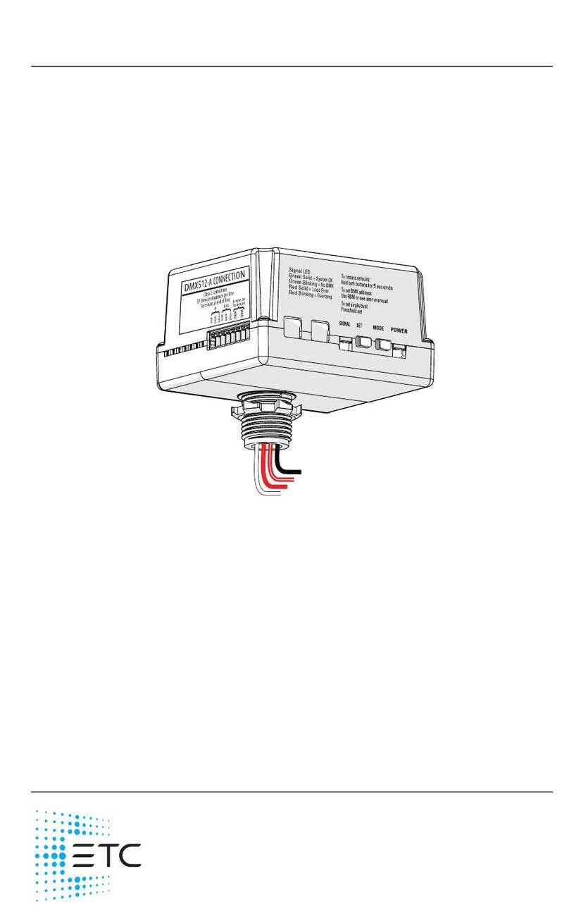
ETC Unison Foundry User manual

ETC Installation Guide
Unison Foundry 0–10 V Controller
Corporate Headquarters
Middleton, WI, USA | +1 608 831 4116
Global Offices
London, UK | Rome, IT | Holzkirchen, DE | Paris, FR | Hong Kong
Dubai, UAE | Singapore | New York, NY | Orlando, FL | Los Angeles, CA | Austin, TX
Web etcconnect.com | Support support.etcconnect.com
Contact etcconnect.com/contactETC | © 2023 Electronic Theatre Controls, Inc.
Trademark and patent info: etcconnect.com/ip | Product information and specifications
subject to change. ETC intends this document to be provided in its entirety.
7179M2160 Rev A Released 2023-02
Overview
The Unison Foundry 0–10 V Controller provides fully-rated 20 A relays for
switched power control with 0–10 V dimming for compatible fluorescent
ballasts and LED drivers. The 0–10 V Controller provides two outputs of
control that can be wired to individual fixtures or used for zone control.
Each output can be configured to a separate DMX address, or both outputs
can be controlled in unison by setting the 0–10 V Controller to single-
channel mode (see
Channel Mode
on
page 8
).
Control connected loads from any DMX control device. Configure the
0–10 V Controller either remotely via RDM (using a tool like Concert) or
locally on the controller. See
Configure the 0–10 V Controller
on
page 8
.
Specifications
Ambient Environment
For indoor use only. Rated for plenum use.
• 0°C to 50°C (32°F to 122°F) operating temperatures in 5%–95%
non-condensing humidity.

ETC Installation Guide
0–10 V Controller
0–10 V Controller Page 2 of 16 ETC
Electrical Specification
The 0–10 V Controller Supports:
• Power input 120–277 VAC, 60 Hz
• Load rating:
- 20 A general purpose, tungsten, or resistive
- 16 A electronic ballast
• Independent control for 0–10 V fluorescent ballasts and/or LED
drivers, each is capable of sinking 100 mA
Compliance
• cULus listed
• Conforms to UL 508 (Industrial Control Equipment), UL 916 (Energy
Management Equipment) and UL 2043 (Plenum rated)
• Certified to CSA C22.2 No. 14 (Industrial Control Equipment) and
No. 205 (Signal Equipment)
Note:
The maximum load on the 0–10 V Controller can be
split between the two relay outputs in any
combination required for the installation, but cannot
exceed the maximum load as specified above.
FCC Compliance
Unison Foundry 0–10 V Controller
(For any FCC matters):
Electronic Theatre Controls, Inc.
3031 Pleasant View Road
Middleton, WI 53562
+1 (608) 831-4116
etcconnect.com
This device complies with Part 15 of the FCC Rules. Operation is subject to the following two
conditions: (1) this device may not cause harmful interference, and (2) this device must accept
any interference received; including interference that may cause undesired operation. Visit
etcconnect.com/products
for current and complete compliance information including FCC
compliance.
Note:
This equipment has been tested and found to comply with the
limits for a Class A digital device, pursuant to Part 15 of the FCC
rules. These limits are designed to provide reasonable protection
against harmful interference when the equipment is operated in
a commercial environment. This equipment generates, uses, and
can radiate radio frequency energy and, if not installed and used
in accordance with the instructions, may cause harmful
interference to radio communications. Any modifications or
changes to this product not expressly approved by Electronic
Theatre Controls, Inc. could void the user’s authority to operate
the product. Operation of this equipment in a residential area is
likely to cause harmful interference, in which case the user will be
required to correct the interference at their own expense.

ETC Installation Guide
0–10 V Controller
0–10 V Controller Page 3 of 16 ETC
Prepare for Installation
The 0–10 V Controller is designed for mounting directly to an electrical
junction box or panel (provided by others) at the electrical lighting load,
upstream of the load in the circuit.
DMX Control Wiring
The 0–10 V Controller connects to a DMX512-A source (provided by ETC or
others) for control.
DMX wiring runs can be daisy chains of up to 32 devices with no Y’s or
loops. Each DMX daisy chain must be terminated for proper control
performance (see
Terminate DMX
on
page 5
).
ETC recommends using Belden 9729 (or approved equivalent) Class 2 wire.
Belden 1583A or equivalent Cat5, Cat5e, or Cat 6 UTP wire is also acceptable
when properly shielded or installed in grounded metal conduit.
A voltage barrier installation box (part number 7187A1000) is available for
installations where DMX control wiring is installed in grounded metal
conduit. Contact ETC to purchase voltage barrier installation boxes if
required.
The total combined length of a DMX wire run (using Belden 9729 or
equivalent) may not exceed 300 m (1,000 ft).
Note:
If your installation requires Class 2 wiring to be
installed in separate conduit, a voltage barrier
installation box is available from ETC. Order ETC part
number 7187A1000.
Note:
All control wiring should be installed and terminated
by a qualified installer and should follow standard
wiring installation practices.
Leave approximately 20 cm (8 in) of wiring available for
connection and to allow slack for future service needs
.
Note:
For more information on DMX control wiring
requirements, see these and other Support Articles at
etcconnect.com:
• support.etcconnect.com/ETC/FAQ/DMX-512-Info
• support.etcconnect.com/ETC/FAQ/DMX_Over_Cat5

ETC Installation Guide
0–10 V Controller
0–10 V Controller Page 4 of 16 ETC
Installation
Installation should follow all local codes and standard electrical practices.
Ensure that the junction box is clean and free of obstructions and that all
wiring is installed correctly.
1. Locate the circuit breaker panel and turn off the power to the lighting
circuit.
2. To gain access to the line voltage wiring, remove the cover plate and
other hardware from the junction box at the load.
3. Mount the 0–10 V Controller to the exterior of the junction box or
panel using the 1/2 in threaded nipple. Use the provided 1/2 in conduit
locknut to secure the 0–10 V Controller to the junction box or panel.
WARNING:
Risk of electric shock! This device utilizes high
voltage and should only be installed by a qualified
installer or electrician. Follow all local codes for
installation. Before terminating the AC power
wiring verify that the main breaker is in the off
position and follow the proper lockout/tag out
procedures per NFPA Standard 70E.
AVERTISSEMENT :
Risque de décharge électrique! Cette appareil
utilise une haute tension et ne doit être installé
que par un installateur qualifié ou un électricien.
Suivez tous les codes locaux pour l'installation.
Avant de raccorder le câblage du courant
alternatif, vérifiez que le disjoncteur principal est
en position d'arrêt et suivez les procédures de
Consignation/Déconsignation prescrites par la
norme NFPA 70E.
WARNING:
For indoor use only! Must install to an electrical
junction box or wireway.
AVERTISSEMENT :
Uniquement pour usage d'intérieur! Doit être
installé sur une boîte de raccordement électrique
ou un chemin de câbles.

ETC Installation Guide
0–10 V Controller
0–10 V Controller Page 5 of 16 ETC
Connect DMX
1. Pull wiring to the junction box.
2. Terminate the DMX cable by following the steps in the termination kit
supplied with the unit.
Terminate DMX
Terminate the last device in the DMX data run for proper control
performance. To terminate the DMX data run at the 0–10 V Controller,
connect the last two pins on the termination connector with a wire jumper
(not included).
Note:
Follow all local code requirements for terminating
wire.
• Notice that the harness wires on the controller are
pre-stripped for your installation convenience.
• Use appropriately sized wire nuts (not provided) to
secure each termination.
Note:
Because resistance is built into the 0–10 V Controller,
no additional resistor is required to terminate the last
device in the DMX data run.

ETC Installation Guide
0–10 V Controller
0–10 V Controller Page 6 of 16 ETC
Connect Power Input and Relay Output
The power input and relay output wiring exits the 0–10 V Controller
through the knockout mount on the enclosure.
1. Connect the power input wiring.
a. Connect the white wire (14 AWG) to the incoming neutral wire
from the breaker panel and the neutral wire of the lighting load.
b. Connect the black power input wire (12 AWG) to the line input
feed wire (hot) from the breaker panel.
2. Connect the relay output wiring. The 0–10 V Controller has two relay
output wires (12 AWG): Zone 1 is red and Zone 2 is red/white.
a. Connect the Zone 1 relay output wire (red) to the hot input of the
first load.
b. Connect the Zone 2 relay output wire (red/white) to the hot input
of the second load.
Note:
When configured to single-channel mode, a single
DMX address controls both relays. If you are using only
one output, cap off the unused wires with wire nuts
(not included).
DMX-512A
Black
Line In
White
Neutral
Load 1
Red
Load 2
Red/White
Dimming
Ballast 1
Dimming
Ballast 2
Gray
0–10 V
Violet Gray/White
0–10 V
Violet/White

ETC Installation Guide
0–10 V Controller
0–10 V Controller Page 7 of 16 ETC
Connect 0–10 V Dimming Output
The 0–10 V dimming output wiring exits the 0–10 V Controller through the
top nipple of the enclosure with the power wiring.
1. Connect the 0–10 V dimming output wiring. The 0–10 V Controller
has two pairs of 0–10 V output wires (18 AWG): Zone 1 is gray and
violet, and Zone 2 is gray/white and violet/white.
a. Connect the Zone 1 output wires, gray (-) and violet (+), to the
control input of the connected load.
b. Connect the Zone 2 output wires, gray/white (-) and
violet/white (+), to the control input of the second connected
load.
2. Reinstall the junction box cover plate.
WARNING:
RISK OF DEATH OR INJURY BY ELECTRIC SHOCK!
0–10 V wiring may not be fully isolated from high
voltage AC power. Do not assume that 0–10 V
wiring is safe to touch, even when run as an NEC
Class 2 signal. Test for AC voltage to ground before
terminating any 0–10 V control wiring to the
device.
AVERTISSEMENT :
RISQUE DE MORT OU DE BLESSURE PAR
ÉLECTROCUTION! Le câblage 0–10 V peut ne pas
être complètement isolé du courant alternatif
haute tension. Ne supposez jamais que le câblage
0–10 V peut être touché en toute sécurité, même
s'il est utilisé avec un signal NEC de Classe 2. Testez
la tension alternative par rapport à la terre avant
de raccorder tout câblage de commande 0–10 V à
l'appareil.
CAUTION:
The 0–10 V control outputs must be treated as
NEC Class 1 control signals, in the same manner as other
high voltage connections.

ETC Installation Guide
0–10 V Controller
0–10 V Controller Page 8 of 16 ETC
Configure the 0–10 V Controller
You can use RDM to set the DMX address and data loss behavior for the
0–10 V Controller. You can set other parameters using RDM, too. See
RDM
Parameters
on
page 15
.
Channel Mode
You can configure the 0–10 V Controller to single-channel or dual-channel
mode using Concert or another RDM controller.
• Single-channel mode: Both relays are assigned to a single DMX
address and function in unison.
• Dual-channel mode: Each relay is assigned a separate DMX address
for control. The second DMX address is always the next sequential
address after the first DMX address, and this cannot be changed. The
0–10 V Controller ships from the factory in dual-channel mode. See
RDM Parameters
on
page 15
.
You can also switch between single-channel mode and dual-channel mode
using the SET button on the 0–10 V Controller. Press and hold the SET
button to switch modes. The POWER LED will blink once for single-channel
mode or twice for dual-channel mode.
DMX Address
You can assign DMX addresses to an entire daisy chain of Unison Foundry
devices using Concert or another RDM controller. If you cannot assign the
DMX addresses using RDM, you can manually set the DMX start address on
the device. The default factory-set DMX address is 1, and the range of
available addresses is 1–512.

ETC Installation Guide
0–10 V Controller
0–10 V Controller Page 9 of 16 ETC
Manually Set the DMX Address
If you cannot assign the DMX addresses using RDM, use the MODE and SET
buttons to set the value of each digit in the three-digit DMX address in
sequence.
Task What to do What you will see
1: Put the controller
into DMX addressing
mode.
Press and hold the MODE
button.
•ThePOWER LED indicator blinks
3 times to indicate that you can set the
100s digit of the DMX address.
•TheSIGNAL LED indicator blinks the
100s digit in the current DMX address.
For example, if the current DMX
address is 201, the SIGNAL LED
indicator blinks 2 times. (If the 100s
digit is a 0, the indicator remains lit and
does not blink.)
2: Set the 100s digit
of the DMX address.
Press the SET button to
set the 100s digit. For
example, press the button
once for 1, twice for 2,
and so forth up to five
times for 5. Press and hold
the SET button for 0.
If the 100s digit in the
new DMX address is the
same as in the current
DMX address, you can
keep the digit by skipping
to step 3.
•ThePOWER LED indicator continues to
blink 3 times to indicate that you are
setting the 100s digit of the DMX
address.
•TheSIGNAL LED indicator blinks the
value that you set for the 100s digit in
the DMX address.
SIGNAL LED
POWER LED
MODE button
SET button
201
10s 1s100s

ETC Installation Guide
0–10 V Controller
0–10 V Controller Page 10 of 16 ETC
3: Set the 10s digit of
the DMX address.
Press the MODE button to
advance to the 10s digit.
•ThePOWER LED indicator blinks
2 times to indicate that you are setting
the 10s digit of the DMX address.
•TheSIGNAL LED indicator blinks the
10s digit in the current DMX address.
For example, if the current DMX
address is 201, the SIGNAL LED
indicator remains lit and does not blink.
•IftheSIGNAL LED indicator rapidly
blinks red, this means that you set the
100s digit to an invalid value (for
example, 6). When this occurs, the
0–10 V Controller exits DMX
addressing mode without saving.
Press the SET button to
set the 10s digit. For
example, press the button
once for 1, twice for 2,
and so forth up to nine
times for 9. Press and hold
the SET button for 0.
If the 10s digit in the new
DMX address is the same
as in the current DMX
address, you can keep the
digit by skipping to step 4.
•ThePOWER LED indicator continues to
blink 2 times to indicate that you are
setting the 10s digit of the DMX
address.
•TheSIGNAL LED indicator blinks the
value that you set for the 10s digit in
the DMX address.
Task What to do What you will see
201
10s 1s100s

ETC Installation Guide
0–10 V Controller
0–10 V Controller Page 11 of 16 ETC
4: Set the 1s digit of
the DMX address.
Press the MODE button to
advance to the 1s digit.
•ThePOWER LED indicator blinks once
to indicate that you are setting the 1s
digit of the DMX address.
•TheSIGNAL LED indicator blinks the 1s
digit in the current DMX address. For
example, if the current DMX address is
201, the SIGNAL LED indicator blinks
once.
•IftheSIGNAL LED indicator rapidly
blinks red, this means that you set the
10s digit to an invalid value. When this
occurs, the 0–10 V Controller exits
DMX addressing mode without saving.
Press the SET button to
set the 1s digit.
If the 1s digit in the new
DMX address is the same
as in the current DMX
address, you can keep the
digit by skipping to step 5.
•ThePOWER LED indicator continues to
blink once to indicate that you are
setting the 1s digit of the DMX
address.
•TheSIGNAL LED indicator blinks the
value that you set for the 1s digit in the
DMX address.
5: Save the new DMX
address.
Press the MODE button. • The POWER LED indicator and SIGNAL
LED indicator return to their normal
functions (see
LED Indicators and
User Interface
on
page 13
).
•IftheSIGNAL LED indicator rapidly
blinks red, this means that you set the
1s digit to an invalid value. When this
occurs, the 0–10 V Controller exits
DMX addressing mode without saving.
Note:
The 0–10 V Controller will exit DMX addressing mode
after 1 minute of inactivity. When this occurs, the
controller retains the DMX address that was saved
before you entered DMX addressing mode.
Task What to do What you will see
10s
201
1s100s

ETC Installation Guide
0–10 V Controller
0–10 V Controller Page 12 of 16 ETC
Data Loss Behavior
You can use RDM to set the behavior of the 0–10 V Controller when DMX
is lost, or you can manually toggle between two options. The 0–10 V
Controller has three options for data loss behavior:
• Go to Full (default data loss behavior)
• Hold Last Look
• Wait and Fade
Manually Set the Data Loss Behavior
You can toggle between “Go to Full” (default option) and “Hold Last Look”
by pressing and holding both the MODE and SET buttons simultaneously.
When both LEDs blink rapidly, release both buttons.
Power Up and Test
1. Restore power to the circuit. The 0–10 V Controller will power up and
turn on all connected loads to full output.
2. Verify that DMX input is present. The green signal LED on the unit
should be lit steadily. If it is blinking, check the DMX wiring.
3. Configure the controller. If additional configuration is required, use an
RDM controller such as Concert software to configure the appropriate
properties. For more detailed information, see the Concert integrated
help system.
4. Test the controller response. Use the DMX control system to alter the
control level, and make sure the 0–10 V Controller responds.
Power-Up Behavior
In the event of a power loss to the 0–10 V Controller (after the initial power
up), the controller will return to the DMX level when power is restored if
DMX is present. If DMX is not present when power is restored, the 0–10 V
Controller will follow the data loss behavior setting, either going to full (for
“Go to Full”) or remaining off (“Hold Last Look” or “Wait and Fade”).
Note:
The “Go to Full” data loss behavior does not meet the
requirements of UL924 for emergency lighting control.
Note:
If you press and hold both buttons too long (past the
rapid blinking into the slow blinking), you will reset
the 0–10 V Controller to factory defaults. See Restore
Defaults on page 14.

ETC Installation Guide
0–10 V Controller
0–10 V Controller Page 13 of 16 ETC
LED Indicators and User Interface
LED Indicator Color State Description
SIGNAL Green
Solid DMX present, system OK.
Slow blinking
DMX absent. Verify that the DMX wiring is
correct, and verify that the DMX source is
functioning correctly.
Rapid blinking
DMX errors. Verify that the DMX wiring is
correct, and verify that the DMX source is
functioning correctly.
POWER Blue Solid Power is OK.
SIGNAL LED
POWER LED
MODE button
SET button

ETC Installation Guide
0–10 V Controller
0–10 V Controller Page 14 of 16 ETC
Update the Software
You can update the software for the 0–10 V Controller using ETC
UpdaterAtor software and an ETC Gadget II or Gateway. Both LED
indicators on the 0–10 V Controller blink during software updates.
Restore Defaults
1. Press and hold both the MODE and SET buttons simultaneously. Both
LEDs will blink rapidly.
2. Continue to hold the buttons until the blinking rate slows.
3. Release the buttons when the blinking rate slows, and the factory
defaults are restored. For factory default values, see
RDM Parameters
on
page 15
.
Note:
If you release both buttons too quickly (during the
rapid blinking), you will change the data loss behavior.
See Manually Set the Data Loss Behavior on page 12.

ETC Installation Guide
0–10 V Controller
0–10 V Controller Page 15 of 16 ETC
RDM Parameters
You can set the following RDM parameters on the 0–10 V Controller using
Concert or another RDM controller.
Parameter ID and Number Description Default Value
Device Label E120_DEVICE_LABEL
0x0082
User-configurable name
for the device
ETC DMX Dual Relay
0–10 V
DMX Start
Address
E120_DMX_START_ADDRESS
0x00F0
DMX address,
range = 1–512 1
DMX
Personality
E120_DMX_PERSONALITY
0x00E0
Sets the channel mode:
• Dual-channel mode
• Single-channel mode
Dual-channel mode
DMX Fail
Mode
(Data Loss)
E137_1_DMX_FAIL_MODE
0x0141
Configures the behavior
when DMX is lost:
•GotoFull
• Hold Last Look
• Wait and Fade
Go to Full
Packet Delay ETC_E120_PACKET_DELAY
0xB000
Requires any change of
level to be present for at
least this number of
packets before action is
taken (open/close the
relay or change 0–10 V
output). Range = 0–50.
0

ETC Installation Guide
0–10 V Controller
0–10 V Controller Page 16 of 16 ETC
Table of contents
Other ETC Controllers manuals

ETC
ETC Echoflex ELED3 User manual

ETC
ETC F-Drive W1 Series User manual

ETC
ETC Unison Mosaic User manual

ETC
ETC Echoflex ELED1H User manual

ETC
ETC EA07 User manual

ETC
ETC Foundation HD User manual

ETC
ETC echoflex ELED2-BCL User manual

ETC
ETC QuickTouch Preset User manual

ETC
ETC Unison Aero Relay Controller User manual

ETC
ETC DMX DEBC-1 User manual

ETC
ETC echoflex ELEDR User manual

ETC
ETC Echoflex ELED1-BUN User manual

ETC
ETC ALiEn2 User manual

ETC
ETC echoflex ELED1 User manual

ETC
ETC ION User manual

ETC
ETC ArcSystem Pro D4 Series User manual

ETC
ETC echoflex ELEDR User manual

ETC
ETC Unison Aero User manual

ETC
ETC Echo Inspire Station Operating instructions
ETC
ETC EchoDIN Power Control Processor Mk2 User manual