ETC Irideon AR250 User manual

instructions
manual

Index
1. Packaging Page. 4
2. Transportation ,, 4
3. Important safety information ,, 5
4. Opening up the projector ,, 6
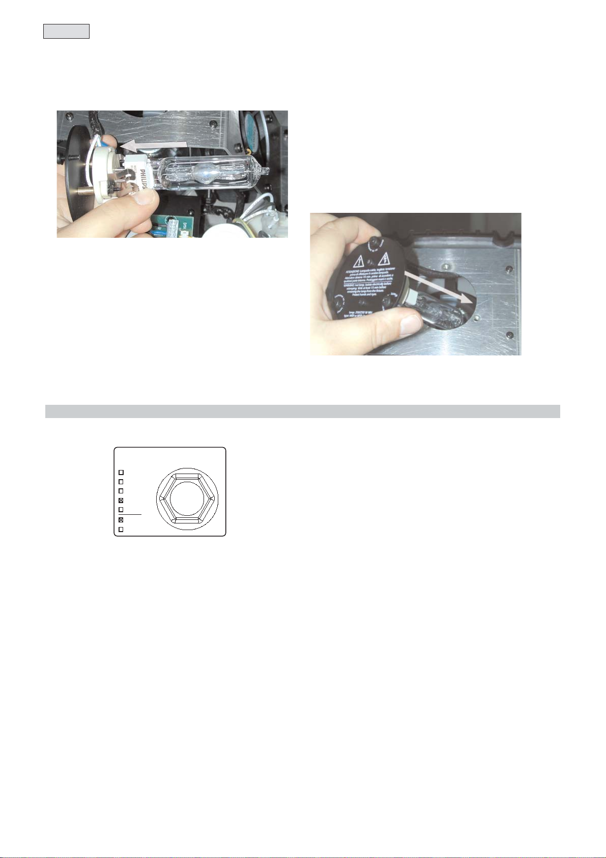
5. Lamp: installation and replacement ,, 7
6. Operating voltage and frequency ,, 8
7. Installation ,, 9
7.1 Installing the unit in weather-protected areas ,, 9
7.2 Installing the unit in exposed areas ,, 9
7.3 Warning ,, 9
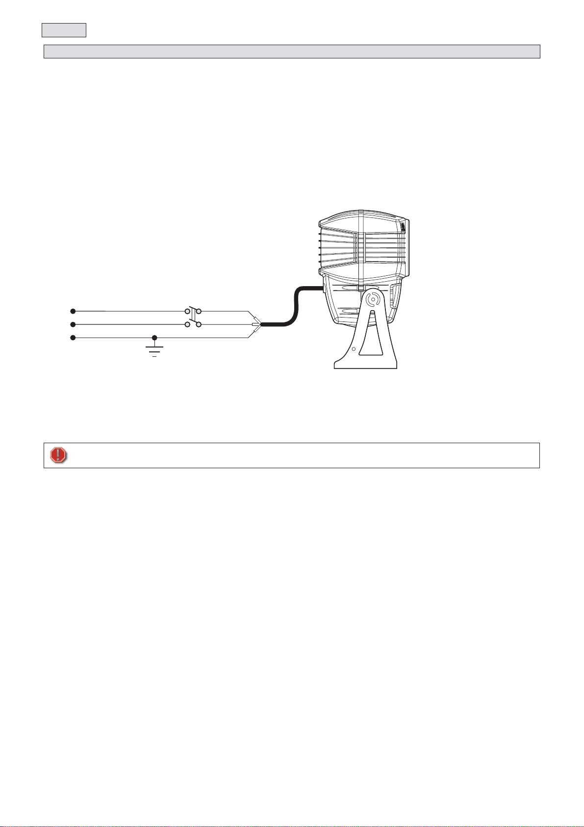
8. Mains connection ,, 10
9. Signal connection ,, 11
9.1 Automated operation - “solo” ,, 11
9.2 Operation via DMX 512 ,, 11
9.3 Synchronising multiple AR 250 fixtures without DMX signal ,, 12
10.Powering up ,, 13
11.DMX addressing ,, 14
12.Display panel functions ,, 15
12.1 Operating modes “mode” ,, 15
12.2 Functions “func” ,, 16
12.3 Parameters and testing “meas” ,, 17
12.4 Quick guide to menu navigation ,, 18
12.5 Rapid scrolling ,, 18
12.6 Double pressing the menu button ,, 18
13.Setting the unit to function automatically “solo” ,, 19
14.DMX 512 functions ,, 20
15.Operating multiple AR 250 fixtures wiyhout DMX 512 ,, 20
15.1 “Master” unit ,, 21
15.2 “Slave” units ,, 21
16.Resetting the counter ,, 22
17.Mechanical adjustments ,, 22
17.1 Tilt adjustment ,, 22
17.2 Altering beam angles by using lenses ,, 23
18.Altering the operating voltage and frequency ,, 25
18.1 Selecting the operating voltage on the autotransformer ,, 25
18.2 Selecting the operating frequency on the power supply ,, 26
19.Opening the front of the projector (Reserved for technical staff) ,, 27
20.Thermal protection ,, 28
21.Servo-controlled fans ,, 28
22.Maintenance ,, 28
23.Electronic motor alignment ,, 29
24.Error messages ,, 30
25.Spare parts ,, 30
3
English

Congratulations on having purchased an ETC product. You have assured yourself of a fixture of the highest quality, both in compo-
nentry and in the technology used.
Following the instructions and procedures outlined in this manual will ensure the maximum efficiency of this product
for years to come.
Open the packaging and ensure that no part of the equipment has suffered damage in transit. In case of damage to the equipment,
contact your carrier immediately by telephone or fax, following this with formal notification in writing.
packing list
Ensure the packaging contains:
1 AR 250
1 owner and installation manual
3 optional prismatic lenses
1. lamp ETC PN RT172 Lamp MSD250W/2
The AR 250 should be transported in its original packaging or in an ETC approved flight case.
During transportation, the packaging or flight case should ensure no movement of the unit.
Failure to do so may result in damage to the unit.
2. Transportation
1. Packaging
English
4

Fire prevention:
1. AR 250 utilizes a Philips MSD 250W/2 lamp or equivalent; the use of any other lamp is not recommended and will null and void
the fixture’s warranty.
2. Never locate the fixture on any flammable surface.
3. Minimum distance from flammable materials: 0.5m (1.6’).
4. Minimum distance from the closest illuminable surface: 2.0m (6.6’).
5. Replace any blown or damaged fuses only with those of identical values. Refer to the schematic diagram if there is any doubt.
6. Connect the projector to mains power via a thermal magnetic circuit breaker.
Prevention against electric shock
1. High voltage is present in the internals of the unit. Isolate the projector from mains supply prior to performing any function which
involves touching the internals of the unit, including lamp replacement.
2. For mains connection, adhere strictly to the guidelines outlined in section 7 of this manual.
3. The level of technology inherent in the AR 250 requires the use of trained technicians
4. A good earth connection is essential for proper function of the projector.
Never operate the unit without proper earth connection.
Protection against ultraviolet radiation
1. Never turn on the lamp if any of the lenses, filters, or the housing is damaged; their respective functions will only operate efficiently
if they are in perfect working order.
2. Never look directly into the lamp when it is operating.
Safety:
1. The projector should always be installed with bolts, clamps, and other fixings which are sufficiently rated to support the weight
of the unit.
2. Always use a secondary safety chain of a sufficient rating to sustain the weight of the unit in case of the failure of the primary
fixing point.
3. The external surface of the unit, at various points, may exceed 150°C (302ºF).
Warning: Never handle the unit until at least 10 minutes after the lamp is turned off.
4. Never install the fixture where unauthorised and untrained personnel may tamper with it.
5. Always replace the lamp if any physical damage is evident.
6. Never install the fixture in an enclosed area lacking sufficient air flow; the ambient temperature should not exceed 35°C (95.0ºF).
7. A hot lamp may explode. always wait for at least 10 minutes to elapse after the unit has been turned off prior to attempting to
replace the lamp.
Always wear suitable hand protection when handling the lamp.
Protection rating of the body against liquids and solids:
1. The fixture has an IP 44 protection rating; this indicates that a particle larger than 1mm (.04”) cannot penetrate the unit and that it
is totally protected against showers of water.
The protection rating allows the fixture to be utilized in an exposed location in inclement weather as long as it is installed according
to the instructions located in section 7.2 “Installing the unit in exposed areas”.
3. Important safety information
5
English

Many of the operations described later in this manual can only be performed with the projector housing opened.
To access the internals of the projector, proceed as follows:
1) Using a Philips head screwdriver, loosen and remove the 11 screws (A) which affix the rear housing (B) of the projector body.
2) Remove the cover (B) from the central seal.
3)You should now have access to the internals of the unit and may carry out the instructions detailed below.
Attention!
Turn off the power prior to opening up the unit.
The fixture’s internal temperature may reach 250°C (482ºF) after 5 minutes, with a maximum peak of 350°C (662ºF).Ensure the
lamp is cold prior to attempting removal. The fixture should be allowed to stand and cool for 10 minutes prior to its removal.
4. Opening the projector
English
6

The AR 250 utilizes a Philips MSD 250W/2 or Philips MSD 250W lamp or equivalent.
The lamp is available from your authorised ETC sales agent:
MSD 250/2
power 250 w
luminous flux 18.000 lm
color temperature 8.500° K
base GY 9,5
approximate lamp life 2000 hours
MSD 250
power 250 w
luminous flux 18.000 lm
color temperature 6.700° K
base GY 9,5
approximate lamp life 2000 hours
To access the lamp, you should proceed as described in section 4 of this manual.
MSD are part of the mercury vapour family of discharge lamps and must be handled with great care. the lamp operates at high pres-
sure, and the slight risk of explosion of the lamp exists if operated over its recommended life.
We recommend, therefore, that the lamp be replaced within the manufacturer’s specified lamp life.
3) Locate the lamp assembly and, using a Philips head screwdriver, loosen the three screws (C) which affix the assembly.
4) Remove the lamp assembly (D).
5) Locate the lampholder (E)
5. Lamp: installation and replacement
7
English

6) Insert the lamp into the lampholder (E).
The lamp used is manufactured from quartz glass and should be handled with care. Always adhere to the instructions supplied in
the lamp’s packaging. Do not touch the glass directly, use the cloth provided with the lamp.The GY 9,5 lampholder is asymme-
trical in construction, with one pin larger than the other. Ensure that the pins are correctly aligned with the appropriate socket.
DO NOT USE UNDUE FORCE. Incase of difficulty, re-read the instructions and repeat the procedure.
7) Replace the lamp assembly into its original position and replace
and retighten the screws
Do not close the unit until all the operations have been performed on the display panel internal to the AR 250.
The fixture may operate at voltages ranging from 100, 115, 208, 230 or 240V .at 50 or 60 Hz. Factory preset voltage is indicated
on the sticker located on the base of the projector, as indicated in the following diagram.
If the specified voltage and frequency do not match those of the country in which you are operating, follow the instructions in sec-
tion 18 of this manual. “Altering the operating voltage and frequency”
Incorrect voltage and frequency selection will detrimentally affect the operation of the projector.
factory set
main at:
100V
115V
208V
230V
240V
50Hz
60Hz
6. Operating voltage and frequency
English
8

Due to its high protection rating AR 250 may be installed in a variety of locations, both indoors and in areas exposed to the ele-
ments.
7.1 Installing the unit in weather protected areas.
AR 250 may be situated in any mounting position when operated in sheltered areas.
In order to allow it to be installed in a variety of locations, the AR 250 is provided with 5 mounting holes (A) of 13mm (0.51”) on
its base; for permanent and secure mounting on any surface.
If hanging the unit from ceiling or a structure, you may utilize the holes (A)which allow for the attachment of a “c” clamp at any posi-
tion through 360°. The structure from which the unit is hung should be of sufficient rating to hold the weight of the unit, as should
any clamps used to hold the unit.
7.2 Installing the unit in exposed areas
The AR 250 may be situated in several mounting positions when installed in an exposed area, thanks to its IP 44 protection rating.
To ensure proper installation, however, there is a simple guideline to follow:
Installing the unit incorrectly may cause damage to occur and will immediately void the warranty.
7.3 Warning
safety chain
When hanging the AR 250 we recommend the use of a safety chain affixed to the appropriate hole (B) on the yoke of the AR
250 and to the suspension device.
This secondary safety attachment should be done using either a metal wire rope or a metal chain, both suitably rated for the pur-
pose.
risk of fire
Every projector produces heat, and should therefore be installed in a well-ventilated position. The minimum distance from flamma-
ble materials: 0.5m (1.64’). The minimum distance from the object being illuminated: 2 m (6.6’).
Attention!
As shown in the diagram, base of the unit must always be facing the ground.
The AR 250 may be adjusted from -45° to +90°.without having to move any other component except the head of the fixture..
Installation in any position other than with the base down, will cause the projector to not perform with its maximum protection rating.
325mm
12
,
80”
185mm
7,3”
140mm
5,51”
==
A
7. Installation
9
English

cabling
The mains cable provided is thermally resistant, complying to the most recent international standards.
In case of cable replacement, similar cable with comparable thermal resistant qualities must be used exclusively (cable 3x1.5 ø external
10mm (.04”), rated 300/500V, tested to 2KV, operating temperature -40°C (-40ºF) +180°C (356ºF))
mains connection
AR 250 can operate at voltages from 100V-115V-208V-230V-240V at 50 or 60Hz (operating voltage and frequency can be selec-
ted as described in section 6 and 18 of this manual). Prior to connecting the unit to your mains supply, ensure that the model in
your possession correctly matches the mains supply available to you.
For connection purposes, ensure your plug is of a suitable rating:
at 230 V: 2 Amps on startup, 1,6 amps constant draw in normal operation
a 115 V: 4,2 Amps on startup, 3,2 amps constant draw in normal operation
Locate the mains cable which exits the base of the unit and connect as shown below:
protection
The use of a thermal magnetic circuit breaker is recommended for each AR 250.
A good earth connection is essential for the correct operation of the fixture. Strict adherence to regulatory norms is strongly recom-
mended.
AR 250 must be earthed; never install the unit unless
the yellow/green earth cable is securely connected.
ground
neutral
live brown
blue
yellow/green
main
8. Mains connection
English
10

AR 250 may operate in 3 different modes:
9.1 Automated operation
9.2 Using DMX 512 signal
9.3 Synchronising AR 250 without DMX 512 signal.
Follow the instructions below which relate to your particular application:
9.1 Automated operation “solo”
AR 250 may operate in stand alone mode in the absence of control signal, using pre-programmed color changing sequence
which can be activated by the multi-function panel on the unit.
9.2 Using DMX 512 signal
Control signal is digital, and is transmitted via two pair screened ø0.5mm cable.
Connection is serial, utilising the data cable sockets located on the base of the AR 250.
signal connection
Connection is to international standards:
Pin 1 gnd = shield
Pin 2 data - = black
Pin 3 data + = white
Connection
Box
Controller
DMX 512
OUT
factory set
main at:
100V
115V
208V
230V
240V
50Hz
60Hz
made in italy by
coemar spa
Castel Goffredo(mn)
Attenzione!
Altatensione all'interno dell'apparecchio. Togliere
tensioneprima di effettuare qualsiasi operazione.
Unabuona connessione di terra e' essenziale.
Contenitoremolto caldo. Non installare su alcuna
superficieinfiammabile. Distanza minima da
materialeinfiammabile: 0,5m. Prima di accendere
l'apparecchioe' indispensabile leggere il manuale
diistruzioni; importanti
informazionidi
sicurezza.
Warning!
Highvoltage inside.
Caution:hot lamp. Disconnect
frompower supply before opening.
Agood ground connection is essential.
Caseis very hot. Do not install on flammable
surfaces.Min. Distance from flammable materials
toall exterior surfaces:0,5m. Important safety
information,see instruction manual before use.
DMX OUT DMX IN
230v
iemax: 2A
ie: 1,6A
max temp ext:
150°C
ta max:
35°C
cos
ϕ:
0,85
IP 44
2 m
2 m
alto/top
115v
iemax: 4,2A
ie: 3,2A
Weight: Kg 16,5
outin
1- shield - GND
2- black - data --
3- white - data +
Connect
to other
AR 250
factory set
main at:
100V
115V
208V
230V
240V
50Hz
60Hz
made in italy by
coemar spa
Castel Goffredo(mn)
Attenzione!
Altatensione all'interno dell'apparecchio. Togliere
tensioneprima di effettuare qualsiasi operazione.
Unabuona connessione di terra e' essenziale.
Contenitoremolto caldo. Non installare su alcuna
superficieinfiammabile. Distanza minima da
materialeinfiammabile: 0,5m. Prima di accendere
l'apparecchioe' indispensabile leggere il manuale
diistruzioni; importanti
informazionidi
sicurezza.
Warning!
Highvoltage inside.
Caution:hot lamp. Disconnect
frompower supply before opening.
Agood ground connection is essential.
Caseis very hot. Do not install on flammable
surfaces.Min. Distance from flammable materials
toall exterior surfaces:0,5m. Important safety
information,see instruction manual before use.
DMX OUT DMX IN
230v
iemax: 2A
ie: 1,6A
max temp ext:
150°C
ta max:
35°C
cos
ϕ:
0,85
IP 44
2 m
2 m
alto/top
115v
iemax: 4,2A
ie: 3,2A
Weight: Kg 16,5
in out
3
2
11 - shield - GND
2 - black - data --
3 - white - data +
1 - shield - GND
2 - black - data --
3 - white - data +
9. Signal connection
11
English

9.3 Synchronising AR 250 without DMX 512 signal.
Multiple AR 250 units may be interconnected in the absence of DMX 512 signal, operating simply via the programs within
the AR 250.
All AR 250s thus connected will operate simultaneously with one unit acting as MASTER and all subsequent units as SLAVES.
Determine which of the AR 250’s will act as master.
Connect the projectors using the data cable (DMX OUT) of the master first unit to connect to the data cable socket (DMX IN) of the
first slave, the out of this slave (DMX OUT) to the in of the second slave (DMX IN) and so on to a maximum of 10 units.
Should you need to connect more than 10 units we recommend that you use a suitable dmx splitter box to achieve this.
These units are usually opto-isolated and may amplify and repeat the signal as required.
Attention! We recommend that the two data cables which remain unconnected should be isolated; the data cable (DMX IN) soc-
ket of the master and the data cable (DMX OUT) socket of the last slave.
Only by suitably isolating these cables will the protection rating of the unit be maintained.
Connection should be to international
standards:
Pin 1 gnd = shield
Pin 2 data - = black
Pin 3 data + = white
Ensure that all data conductors are
isolated from one another and the
metal housing of the connector.
Pin 1 should never be connected to
mains power.
master slave
Connection
Box
factory set
main at:
100V
115V
208V
230V
240V
50Hz
60Hz
made in italy by
coemar spa
Castel Goffredo (mn)
Attenzione!
Altatensione all'interno dell'apparecchio. Togliere
tensioneprima di effettuare qualsiasi operazione.
Unabuona connessione di terra e' essenziale.
Contenitoremolto caldo. Non installare su alcuna
superficieinfiammabile. Distanza minima da
materialeinfiammabile: 0,5m. Prima di accendere
l'apparecchioe' indispensabile leggere il manuale
diistruzioni; importanti
informazionidi
sicurezza.
Warning!
Highvoltage inside.
Caution:hot lamp. Disconnect
frompower supply before opening.
Agood ground connection is essential.
Caseis ver y hot. Do not install on flammable
surfaces.Min. Distance from flammable materials
toall exterior surfaces:0,5m. Important safety
information,see instruction manual before use.
DMX OUT DMXIN
230v
iemax: 2A
ie: 1,6A
max temp ext:
150°C
ta max:
35°C
cos
ϕ:
0,85
IP 44
2 m
2 m
alto/top
115v
iemax: 4,2A
ie: 3,2A
Weight: Kg 16,5
out Connect
to other
AR 250
(slave)
factory set
main at:
100V
115V
208V
230V
240V
50Hz
60Hz
made in italy by
coemar spa
Castel Goffredo (mn)
Attenzione!
Altatensione all'interno dell'apparecchio. Togliere
tensioneprima di effettuare qualsiasi operazione.
Unabuona connessione di terra e' essenziale.
Contenitoremolto caldo. Non installare su alcuna
superficieinfiammabile. Distanza minima da
materialeinfiammabile: 0,5m. Prima di accendere
l'apparecchioe' indispensabile leggere il manuale
diistruzioni; importanti
informazionidi
sicurezza.
Warning!
Highvoltage inside.
Caution:hot lamp. Disconnect
frompower supply before opening.
Agood ground connection is essential.
Caseis ver y hot. Do not install on flammable
surfaces.Min. Distance from flammable materials
toall exterior surfaces:0,5m. Important safety
information,see instruction manual before use.
DMX OUT DMXIN
230v
iemax: 2A
ie: 1,6A
max temp ext:
150°C
ta max:
35°C
cos
ϕ:
0,85
IP 44
2 m
2 m
alto/top
115v
iemax: 4,2A
ie: 3,2A
Weight: Kg 16,5
in out
1 - shield - GND
2- black - data --
3- white - data +
1 - shield - GND
2- black - data --
3- white - data +
English
12

To perform the operations which follow, from sections 10 to 18, with the exception of 17, the projector housing should be open. If you
have since closed the unit up, reopen the housing as described in section 4.
After having followed the preceding steps, turn on the power to the unit.
If you have chosen to control the AR 250 using a DMX 512 controller, you should always turn on the power to the controller first.
The fixture will perform a reset function on its internal motors. This will last some few seconds, after which it will be subject to the
external signal from the controller.
Software version
On powering up, the led display of the projector will display the currently installed software version for a few seconds.
For example, it may show:
R 2.01 (software version 2.01).
Ventilation
The projector is fitted with 2 fans for forced cooling of the unit.
The two fans are directly controlled by the onboard software and may be switched off after powering up, depending upon the set-
tings shown in the display. They may never be switched off when the lamp is turned on.
To turn on the fans, you will need to either alter the settings via the display panel, as described in section 11.2, or turn the lamp on.
DMX 512 signal reception
After the software version has been displayed, the projector will proceed with its reset function. On completion of this, the display
will remain static on, indicating that the projector is correctly receiving DMX 512 signal.
A001 (dmx address 001).
If the display flashes, the projector is not receiving signal correctly. Check the cabling and the functioning of the controller.
turning on the power with no dmx signal connected
After the display has shown the software version, the projector will perform a reset. When completed, the display will flash to indi-
cate the absence of DMX 512 control signal.
messages other than A001
On powering up, the AR 250 may display values other than A001, the ETC default setting.
The display may show:
DMX 512 operation
1) A001 DMX 512 operation, address 1 (for example)
automated master/slave or automated “solo”
2) PRG.1 master projector, program 1,auto memory stepping, adjustable.
3) -SL- slave projector, operation determined by the “master” unit attached
Advanced operation information on each of these modes is contained in the sections which follow.
10. Powering up
Important Information
13
English

Each AR 250 utilizes 6 channels of DMX 512 signal for complete control.
To ensure that each unit accesses the correct signal, it is necessary to correctly address each fixture. Any number between 1 and 506
can be generated via the multifunction panel of the unit AR 250.
This procedure must be carried out on every unit being utilized.
When powered up initially, each projector will show A001 which indicates DMX address 1; a projector thus addressed will respond
to commands on channels 1to 6from the DMX 512 controller. A second projector should be addressed as 7a third as 13 and
so on until the final unit has been addressed.
DMX 512 should be carried out so that there is no overlap in the assigned addresses. This will allow your controller to accurately
address each individual parameter of your AR 250s.
altering dmx addresses
1) Press the + or - buttons until the display shows the DMX address required. The characters in the display panel will flash to indicate
that the selection is not stored in memory.
2) Press the enter button to confirm your selection; the display will stop flashing and the projector will now respond to the new
DMX 512 settings.
3) To better understand the functions of each DMX 512 we refer you to section 14 “Operation via DMX 512”.
Important Note: Keeping the + or - button pressed will cause the display to alter at increase speed, allowing a faster selection to be
effected.
Note: Channel order and function table can be found on page 20.
A
001
menu enter +
11. DMX addressing
English
14

The display panel of the AR 250 is used to display and set function information and alter various parameters.
Altering the ETC factory settings may vary the functioning of the projector, causing it to not respond to external DMX 512 signal.
Please read and familiarize yourself with the following information very carefully before altering any selections.
NOTE: the +symbol is used in these instructions to indicate the action of pressing a button as described in the text.
12.1. Operating mode (MODE)
AR 250 allows the user to select one of several operating modes:
A detailed description about altering these settings may be found in sections : 13,14,15.
DMXDMX mode
the fixture operates with DMX 512 ☞
enter
--MA-- master mode
master fixture
MODEfunctioning mode
to select the functioning mode
☞
menu
AOO1
-– S L -–
see chapter 13
☞
enter
☞
+
PRG1
P.L.RM
random programs
playback
to
PROGprogram
to select a given program for
playback
☞
enter
PRG.1
program 1 ☞
enter
☞
+
☞
+
☞
+
☞
enter 0.1
to
460.0
☞
+
WAIT tempo d’attesa
wait time between
programs (in seconds) ☞
+
P.ALL
all programs ☞
enter
PRG9
☞
enter
☞
enter
☞
+
☞
+
☞
enter ☞
enter
☞
enter
-– S L -– slave
slave fixture
12. Display panel functions
15
English

12.2. Functions (FUNC)
The projector allows the altering of several functions and select personalized settings.
Settings available via the “FUNC” menu are able to be altered at any time regardless of the operating mode “MODE” selected.
AA
on the ground
suspended
FUNC
menu funzioni
Ithe fixture allows you to
modify some of the settings
in order to customize its
functioning according to
your needs
☞
menu
☞
+
AOO1
LAMPlamp control
lamp control vi aDMX signal or lamp
always on.
FANSfans control
fans always on or electronically controlled.
DISPdisplay direction
to reverse the display’s reading direction
LED display control
turns the display off
SH.PRshow program
the display shows the selected programs
through channel 5 and not the DMX ad-
dress
☞
enter
☞
enter
☞
enter
☞
enter
☞
+o–
☞
+o–
☞
+o–
☞
+o–
☞
+o–
☞
+o–
STRD
automatic control
ON
fans always on
☞
enter ☞
+o–
☞
+o–
☞
enter
AA
☞
enter
☞
enter
☞
enter
☞
enter
☞
enter
☞
enter
☞
enter
☞
enter
☞
enter
☞
enter
☞
+o–
☞
+
-– -– -– -–
reset
SURE
blinks
MODE
☞
enter ☞
+o–☞
enter
☞
enter
☞
+
☞
enter ☞
+o–☞
enter
keep pressed
☞
enter
keep pressed
☞
+
STRD
lamp control
via DMX 512
ON
lamp always on
OFF
turns the display off (☞any
key to turn it back on)
OFF
function inhibition
ON
function activation
LAMP
lamp test
FANS
fans manual test
☞
+
☞
+
☞
+
☞
enter
☞
+
☞
enter
☞
+o–
☞
+o–
DFSE default settings
brings all settings back to default (except for
recorded programs and alignment)
RESE reset
all motors reset
EXAMexam
lamp and fans individual tests
English
16

12.3. Parameters and testing (MEAS)
The internal microprocessor of the AR 250 allows for several diagnostic and output parameters to be displayed.
The TEST function may record, in this menu, information regarding settings to be adopted when starting up without dmx signal.
TEMP temperature
internal temperature
VOLTmains voltage
measures the mains voltage.
Consider abnormal values lower than 26V and
higher than 36V.
DMIN DMX value on every channel
reading of the DMX value of each of the 6 chan-
nels used by AR 250 on the DMX 512 line.
RATE DMX rate
DMX 512 rate reading
S.FAN fans speed
fans speed
HOUR hours of functioning
reading of the fixture’s life (in hours)
TEST test
tests
MEAS
☞
menu
☞
+o–
AOO1
10
value reading
589
value reading
1230
value reading
24.S0
value reading
58C
temperature reading
CH01
channel 1
CH06
channel 6
30.0V
tension reading
10
DMX value
reading
255
DMX value
reading
☞
enter
☞
enter
☞
enter
☞
enter
☞
+o-
☞
enter
☞
enter
☞
+
☞
enter
☞
enter
☞
enter
☞
+
DIMM
test dimmer
CYAN
test cyan
MAG
test magenta
YELL
test yellow
STOR
to record the position in which
the fixture stops at the end of the reset
procedure with no signal
☞
+
☞
+
☞
+
☞
+
☞
+☞
enter
☞
+
☞
+
LIFE
lamp’s life after
last test
LIFS
all lamps’
life
UNIT
fixture’s life
☞
enter
☞
+RIGH
right fan
LEFT
left fan
☞
enter
☞
enter
☞
+
☞
+
☞
+o-
☞
enter
☞
enter
3400
DMX value
reading
3400
DMX value
reading
17
English

12.4. Quick guide to menu navigation
For your convenience, the following is a guide to navigating the menu system of the projector.
12.5. Rapid scrolling
Via the AR 250 display, it is possible to rapidly scroll through the various numbers displayed in the menu which apply to the follo-
wing 3 uses:
1) Pressing down and holding the + or - buttons will cause the numbers to scroll more quickly than by simply pressing buttons repea-
tedly
2) Pressing down the + button and then the - button and holding them down simultaneously will cause the numbers to jump to
the highest possible value available in the particular function.
3) Pressing down the - button and then the + button and holding them down simultaneously will cause the numbers to jump to
the lowest possible value available in the particular function.
12.6. Double pressing the menu button
Pressing the menu button twice, at any level in the navigation menu, will immediately return you to the last function in which chan-
ges were confirmed (saved).
P.L.RM
☞
+P.ALL
MEAS
LED
☞
+
☞
+
☞
+
LAMP
☞
+
FANS
☞
+
DISP
RESE
DFSE
AOO1
FUNC
A007
A007
MODE
☞
enter
☞
enter
☞
menu
PRG.1
AOO1
☞
enter
☞
enter
--
SL
--
☞
enter
☞
+
☞
enter LIFE
VOLT
DMIN
RATE
HOUR
TEMP
LIFS
UNIT
☞
+
☞
+
☞
+
☞
+
TEST
☞
+
DIMM
CYAN
MAG
YELL
STOR
☞
+
☞
+
☞
+
☞
+
☞
enter
--
MA
--
DMX
☞
+
☞
+
☞
+
PRG.1
--
SL
--
☞
enter
☞
+
☞
+
☞
+
☞
+
WAIT
PROG
to
☞
+PRG.9
☞
enter
☞
+
☞
enter
AU.DL
☞
enter
S.H.PR
S.FAN
☞
+
☞
+o–
☞
enter
English
18

AR 250 may operate automatically, carrying out pre-recorded color changes.
No cables should be connected to the data input sockets, as described in section 9.1 “automated operation “solo”.
1) Press the menu button, the display will show MODE.
2) Press the enter button, the display will show DMX (for dmx function).
3) Press the +button until the display shows-MA- (for master).
4) Press the enter button to confirm you selection; the letters-MA- will flash momentarily and then the display will show the pro-
gram detailsPRG., for program,, with the relevant number (9 available programs from 1to9 sequentially).
You may now alter the preset parameters:
Altering the delay between color changes in a program.
1) The display shows PRG. 1 (program 1 is running, for example).
2) Press the enter button.
3) Press the +button until the display shows WAIT (wait).
4) Press the enter button. The display will show a numerical value which corresponds to the current delay between color changes
5) Press the +button to obtain the required time delay (between 0,1 and 460 seconds).
6) Press the enter button to confirm your selection. The display will flash and then return automatically to the original PRG.1 dis-
play, recording the time delay you have selected.
Selecting an alternative program to that currently running.
1) The display shows PRG.1 (program 1, for example)
2) Press the enter button.
3) Press the +button until the display shows PROG (program).
4) Press the enter button. The display will show a numerical value which corresponds to the currently running program PRG 1 (for
example, program 1).
5) Press the +button to select the number of the required program.
The AR 250 provides numerous color change combinations in the internal memory of the projector, grouping them with conside-
ration to the tonality and speed of the color changes:
Program 1: all possible color combinations in a smooth, slow sequence
Program 2: saturated colors in a smooth, slow sequence
Program 3: pastel colors in a smooth, slow sequence
Program 4: bright colors in a smooth, slow sequence
Program 5: all possible color combinations at a faster speed with respect to programs 1 to 4.
Program 6: saturated colors at a faster speed with respect to programs 1 to 4.
Program 7: pastel colors at a faster speed with respect to programs 1 to 4.
Program 8: bright colors at a faster speed with respect to programs 1 to 4.
Program 9: a sequence of color changes of varying tonality and speed.
6) Press the +button further and the AR 250 will display P.ALL (all programs, played back in order) and P.L.RM (all programs,
played back randomly).
N.B. Note that prior to recording, the decimal point will not appear preceding the program number.
7) Press the enter button to confirm your selection. The display will flash and display, for example, PRG.2 recording the change
you have made
NOTE: the -button has the effect of returning the display to the previous function.
13. Setting the unit to function automatically “solo”
19
English

AR 250 may be controlled using the DMX 512 control protocol. Connection should be as described in section ”9.2 Operation
via DMX 512”.
If you have correctly followed all the steps described up to this point, your DMX5 512 controller will allow you complete control
of all the functions of the AR 250 as described in the following table.
Turning on the lamp
Note that the table above indicates that to turn on the lamp channel number 7 of your DMX 512 controller should be set to between
(241 and 255), to turn it off, channel 4 must have a value between 11 and 30.
You may force the lamp to turn on automatically on startup using the display panel, as described in section ”11.2 Display panel
functions” in the text describing the “Func”, lamp ON” function.
channel function type of control effect decimal percentage
1dimmer step closed 0-7 0-2.75
proportional from close to open 8-255 3.14-100
2cyan step
white clear 0-7 0-2.75
proportional
proportional cyan control from white to cyan 8-255 3.14-100
3magenta step
white clear 0-7 0-2.75
proportional
proportional magenta control from white to magenta 8-255 3.14-100
4Yellow step
white clear 0-7 0-2.75
proportional
proportional yellow control from white to yellow 8-255 3.14-100
5
Auto function step No effects 0-9 0-3.53
step Auto program 1 (all colors, slow color fade) 10-33 3.9-13
step Auto program 2 (saturated colors, slow color fade) 34-56 13.3-22
step Auto program 3 (pastel colors, slow color fade) 57-79 22.3-31
step Auto program 4 (light colors, slow color fade) 80-102 31.3-40
step Auto program 5 (all colors, medium speed color fade) 103-125 40.3-49
step Auto program 6 (saturated colors, medium speed color fade) 126-148 49.3-58
step Auto program 7 (pastel colors,medium speed color fade) 149-171 58.3-67
step Auto program 8 (light colors, medium speed color fade) 172-194 67.3-76
step Auto program 9 (mixed color sequence, color fade at different speed 195-217 76.3-85
step Random program 218-240 85.3-94
step All programs 241-255 94.3-100
6
Lamp on/off/ reset step lamp off 0-10 0-3.92
step Park (no function) 11-30 4.3-11.7
step cmy and dimmer reset (only once) 31-45 12-17.6
step cmy reset (only once) 46-60 18-23.5
step Program stop 61-80 23.9-31.3
proportional Selected auto-program pause time control (1 sec/8 min) 81-241 31.7-94.5
step lamp on 242-255 95-100
Date: 05/2002
Release: 1
Display panel can inhibit lamp off function
note 1: Channel 6 has a delay time of 6 second to prevent accidental activation.
note 2 :on/off lamp mode is not affected unless an opposite value is received
Chart name: DMX 512
Fixture type: AR 250
14. DMX 512 functions
English
20

Multiple AR 250 fixtures can operate in the absence of control signal by executing internally stored, pre-recorded programs
Projectors correctly connected together may operate in synchronised mode, the AR 250 receiving signal being denominated as
“slave” units and those generating control signal designated as “master” units.
To activate this automated function, projectors must be connected together as described in the section entitled 9.3.
“Synchronising multiple AR 250 fixtures without using DMX512”; No signal cables should be connected to
the external data input sockets.
Power up the projector and use the 4 button menu system and the display panel to set the units correctly.
15.1 “Masters”
AR 250 may operate automatically with output in the form of pre-recorded programs, as described in section “9.3.
Synchronising multiple AR 250 fixtures without using DMX512” Only one unit may be designated as “master”.
Selecting a master unit is simply a matter of convenience and accessibility to the display panel:
1) Press the menu button, the display will show MODE.
2) Press the enter button, the display will show DMX (for dmx function).
3) Press the +button until the display shows -MA- (for master).
4) Press the enter button to confirm you selection; the letters -MA- will flash momentarily and then the display will show the pro-
gram details PRG., for program,, with the relevant number (9 available programs from 1to 9sequentially).
You may now alter the preset parameters:
Altering the delay between color changes in a program.
1) The display shows PRG. 1 (program 1 is running, for example).
2) Press the enter button.
3) Press the +button until the display shows WAIT (wait).
4) Press the enter button. The display will show a numerical value which corresponds to the current delay between color changes
5) Press the +button to obtain the required time delay (between 0,1 and 460 seconds).
6) Press the enter button to confirm your selection. The display will flash and then return automatically to the original PRG.1 dis-
play, recording the time delay you have selected.
Selecting an alternative program to that currently running.
1) The display shows PRG.1 (program 1, for example)
2) Press the enter button.
3) Press the +button until the display shows PROG (program).
4) Press the enter button. The display will show a numerical value which corresponds to the currently running program PRG 1 (for
example, program 1).
5) Press the +button to select the number of the required program.
The AR 250 provides numerous color change combinations in the internal memory of the projector, grouping them with conside-
ration to the tonality and speed of the color changes:
Program 1: all possible color combinations in a smooth, slow sequence.
Program 2: saturated colors in a smooth, slow sequence.
Program 3: pastel colors in a smooth, slow sequence.
Program 4: bright colors in a smooth, slow sequence.
Program 5: all possible color combinations at a faster speed with respect to programs 1 to 4.
Program 6: saturated colors at a faster speed with respect to programs 1 to 4.
Program 7: pastel colors at a faster speed with respect to programs 1 to 4.
Program 8: bright colors at a faster speed with respect to programs 1 to 4.
Program 9: a sequence of color changes of varying tonality and speed.
6) Press the +button further and the AR 250 will display P.ALL (all programs, played back in order) and P.L.RM (all programs,
played back randomly).
Note that prior to recording, the decimal point will not appear preceding the program number.
7) Press the enter button to confirm your selection. The display will flash and display, for example, PRG.2 recording the change.
15.2 “slaves”
All projectors which are connected to a “Master” unit should be set to “Slave”. Connections should be as described in section “9.3
Synchronizing multiple AR 250 fixtures without DMX 512”.
“Slave” units are recognisable since they have connections made to both XLR sockets in their base, except for the final unit in the
chain which has only one connection to its “DMX IN”.socket.
Once this is complete, you may proceed to set up units as “Slave”.
1) Press the menu button, the display will show MODE.
2) Press the enter button, the display will show DMX(for dmx function).
3) Press the +button until the display shows -SL- (for slave).
4) Press the enter button to confirm you selection; the letters -SL- will flash momentarily and then remain static.
When the display shows -SL- it confirms that it has accepted the setting as Slave and is ready to accept input instructions from a
Master unit.
15. Operating multiple AR 250’s in synchronized mode without DMX 512
21
English
Table of contents
Other ETC Lantern manuals

ETC
ETC ArcSystem Navis 100 User manual

ETC
ETC Source Four jr User manual

ETC
ETC High End Systems SolaFrame Studio User manual

ETC
ETC ARCP1 User manual

ETC
ETC IRIDEON AR500 Assembly instructions

ETC
ETC IRIDEON AR500 Installation instructions

ETC
ETC IRIDEON AR500 User manual

ETC
ETC ETC 405 User manual

ETC
ETC TURBO RAY User manual
Popular Lantern manuals by other brands

Coleman
Coleman CONQUER SPIN 550L manual

DreamLED
DreamLED COSY QI WDL-200 quick start guide

Prilux
Prilux Egea XL PLAY instruction manual

Lumiglas
Lumiglas USL06-Ex Installation and operating instructions

brennenstuhl
brennenstuhl SOL SV0805 P1 IP 44 Instructions for installation and use

Vector
Vector TOUGH BRITE VEC146 Owner's manual & warranty