ETC Echo Keyswitch Station User manual

ETC Installation Guide
Echo Keyswitch Station
Corporate Headquarters nMiddleton, Wisconsin, USA nTel +608 831 4116
Service (Am er icas) nservice@etcconnect.com
London, UK nTel +44 (0)20 8896 1000 nService: (UK) service@etceurope.com
Rome, IT nTel +39 (06) 32 111 683 nService: (UK) service@etceurope.com
Holzkir c hen, DE nTel +49 (80 24) 47 00-0 nService: (DE) techserv-hoki@etcconnect.com
Hong Kong nTel +852 2799 1220 nService: (Asia) service@etcasia.com
© 2018 Electronic Theatre Controls, Inc. nTrademark and patent info:etcconnect.com/IP
Web: etcconnect.com nProduct information and specifications subject to change.
ETC intends this document to be provided in its entirety.
7140M2120 nRev B nReleased 2018-11
Overview
Unison Echo Keyswitch Station enables security for
stations within a space by preventing unwanted control-
activation from all stations within the space while the
keyed lockout is enabled.
The Keyswitch Station is designed for use with any
EchoConnect-enabled system including Echo Zone
Controllers, Echo Relay Panels, Sensor3 and Unison DRd
with Echo architectural control processor.
For use with ETC dimming and relay products.
Prepare for Installation
Keyswitch Stations ship with station electronics, faceplate,
termination kit, (2) keys, and installation hardware.
The station installs into an industry standard single-gang back box (RACO 690
or equivalent - provided by others) or an optional surface mount back box (part
number 7081A2004-1) sold separately and available from ETC.
Environmental
For indoor installation only - 0-50° C, 5-95 % non-condensing humidity.
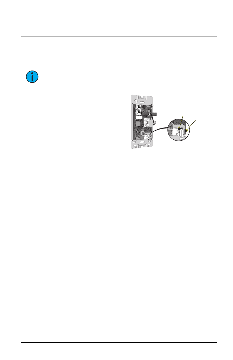
Installation
Installation should follow all local codes and standard electrical practices. The
back box should be installed level and square for best results. Ensure that the
back box is clean and free of obstructions.
Note: NEC Class 2 product to be wired in accordance to NEC Article
725 and local jurisdiction requirements.

ETC Installation Guide
Keyswitch Station
Note: When using Category 5 (or equivalent) cable on the EchoConnect
communication bus, please note the following:
•
Cat5 wiring must be terminated using EchoConnect Cat5
Termination Kit and must be installed using a bus topology.
Refer to the installation guide that is provided with the Cat5
Termination Kit (7186A1207) for information to terminate
Cat5 wiring.
•
Not all topologies are supported using Cat5; careful planning
is required to ensure the proper termination kits are available
and the wire is pulled appropriately.
Set Space and Address
The Keyswitch Station participates in an Echo system using the configured
Space and Address which are selectable using the rotary switches on the back
of the station.
Each station must be set to a unique
station address for the assigned space. By
default, these switches are set to Space 1,
Address1. Commands are shared by all
devices within an assigned space.
1. Set the Space rotary switch to the
desired number (1 through 16) for
the space you want the station to
provide lockout.
2. Set the Address rotary switch to
the desired address (1 through 16)
for the station identification in the
assigned Space.
CAUTION: Each station must have it station address set to a unique
number (1 through 16) for the space it controls. If two or more stations
use the same address for the same space, the system will not function
properly.
DIP Switches
DIP switches are located on the rear panel of the station. The default position
for all DIP switches is Off which provides space lockout. To enable the
Keyswitch Station for custom configuration using EchoAccess, set DIPswitch
2 On. Reference the mobile app integrated help system for information to
configure custom actions available to the Keyswitch Station.
Echo Keyswitch Station Page 2 of 4 Electronic Theatre Controls, Inc.

ETC Installation Guide
Keyswitch Station
Connect the Wiring
1. Pull all required wiring (data+, data-) and an additional 14AWG
(2.5mm2) ESDground wire into the back box.
Note: A ground connection is required between every station and back
box, even when installed with grounded metal conduit.
EchoConnect
ESD
ground
2. Connect station ESD ground
wire pigtail.
a. Strip 7/16” (11 mm) of
insulation from the
ends of the station
ground wire pigtail,
provided in the
termination kit, and
the incoming ground
wire.
b. Use one WAGO 221 Series LEVER-NUTS®provided in the
termination kit to connect the station ESD ground pigtail and the
incoming ground. For stations using grounded metal conduit,
connect the ground pigtail to the metal back box ground location.
c. Install the ESD ground wire pigtail FASTON connector to the
mating receptacle on the station electronics.
3. Terminate EchoConnect wires. EchoConnect is topology free, you may
install the wires in any combination of bus, star, loop, or home-run.
a. Strip 7/16” (11 mm) from the ends of each power pigtail wire
provided in the termination kit and the installed control wires.
b. Use the WAGO connectors provided to connect the power pigtail
wires and the installed Belden 8471 control wires. One WAGO
should be used for the white wire pair (data +) and one for the
black wire pair (data -). Open the terminal levers on the WAGO
connector and insert the installed Belden 8471 wire and the lead
from the power pigtail into the terminals then close the levers.
c. Install the two pin connector from the power pigtail to the
mating receptacle on the station electronics.
Echo Keyswitch Station Page 3 of 4 Electronic Theatre Controls, Inc.

ETC Installation Guide
Keyswitch Station
Installing the Station in the Back Box
1. Insert the station
electronics and wiring into
the back box. The arrow on
the mounting plate must
point up.
2. Use receptacle spacers as
needed to provide a flush
mounted station. These
spacers are not required for
a surface mount
installation.
a. Fold the spacer in a zig-zag fashion and press them together to
achieve the required thickness to fill the gap between the
station, wall surface, and the back box.
b. Cut off and discard the excess.
c. Place the stack between the station electronics and the flush
mounted back box.
3. Secure the station with two screws. If using spacers, insert the screws
through the spacers as well.
Installing the Faceplate
The faceplate is secured to the station with two magnets that are located on
the bottom edge of the faceplate.
1. Align the top of the faceplate approximately 20
degrees to the station.
2. Hook the top of the faceplate on the tabs located on
the top of the station electronics assembly. Toensure
the faceplate is hooked properly on the top hook,
wiggle it slightly side to side while the bottom is
angled about 20 degrees from the wall.
3. Swing the bottom of the faceplate down until the
magnets engage.
4. If the faceplate does not fully attach, wiggle the
bottom of the plate until the magnets are seated
properly to the station and the faceplate is secure.
Using the Keyswitch
Turn the provided key to perform the configured event. Space lockout toggle
is the default action. Turn the key again to toggle the event off. Reference
DIP
Switches on page2
for information to configure custom events.
Echo Keyswitch Station Page 4 of 4 Electronic Theatre Controls, Inc.
Table of contents
Popular Security System manuals by other brands

Bentel Security
Bentel Security KRP10 operating instructions

ADEMCO
ADEMCO 4130XM user manual

Fireboy- Xintex
Fireboy- Xintex DU-RBH-01 Owner's Manual & Installation Instructions

Mobeye
Mobeye PowerGuard CM2100 user manual

Risco
Risco SecuSafe EL4855PI quick start guide

Compu-TTY
Compu-TTY KA300TX instruction manual