ETCR 2800B User manual


1

2
Content
Attention Items:..........................................................................................................................................................3
I. BriefIntroduction....................................................................................................................................................3
II. ModelDifference...................................................................................................................................................3
III.TechnicalSpecifications.......................................................................................................................................4
IV. DetectorStructure.................................................................................................................................................5
V.Network Structure..................................................................................................................................................5
VI.The Principle andApplication ofDetection.........................................................................................................6
VII.Wiring Instructions.............................................................................................................................................9
VIII.Install Caution ...................................................................................................................................................9
IX. PowerSupply WayChoice...................................................................................................................................9
X.Basic Equipment....................................................................................................................................................9

3
Attention Items:
Thank you forpurchasing ETCR2800seriesproducts Non-ContactGroundResistance Online Detector
ofthe companyIn orderto make betteruse ofthe productplease be certain:
To read thisusermanualcarefully.
To complywith the operating cautionspresentedin thismanual.
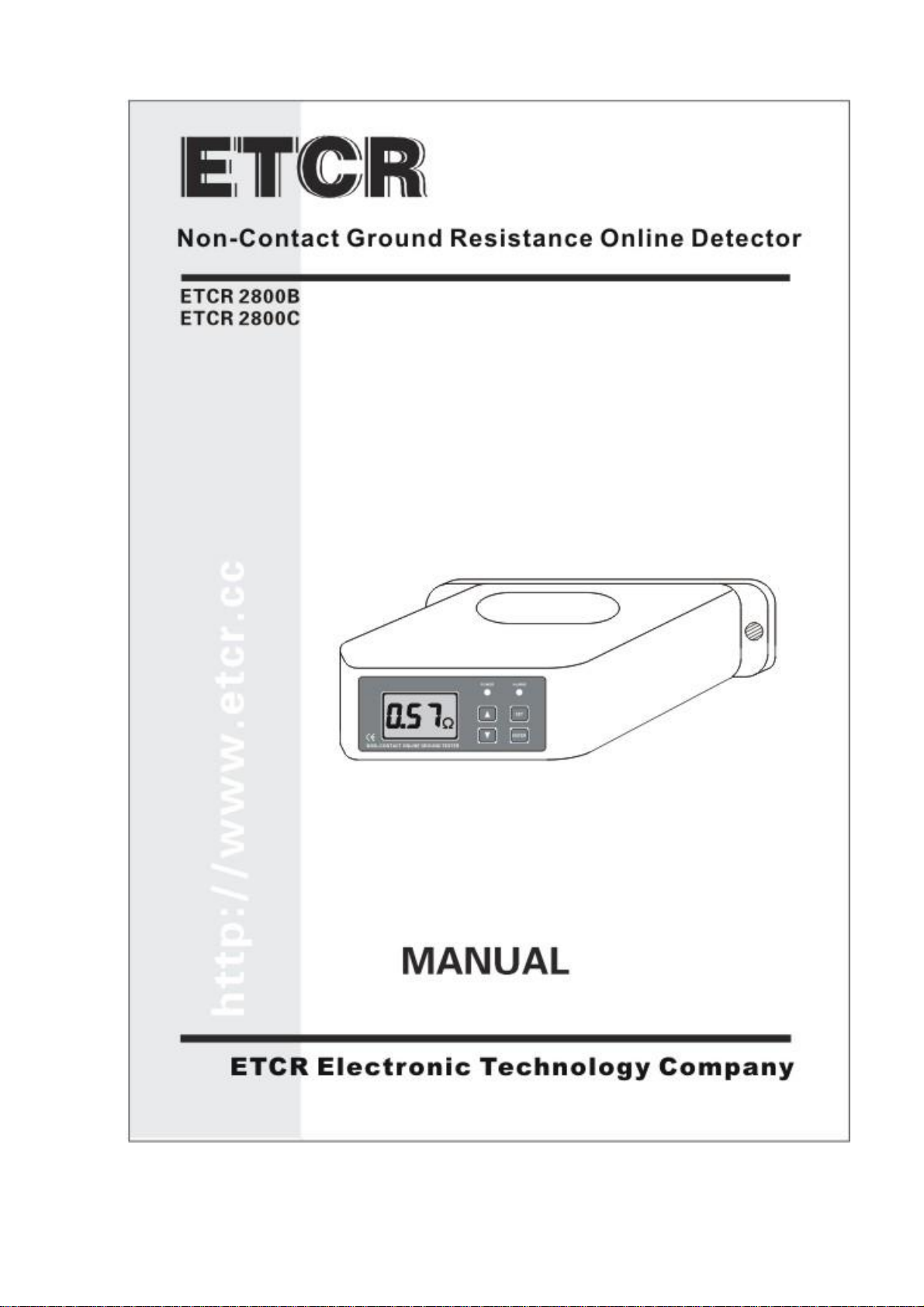
lApplytoreturncircuit ground resistance, metallicreturnconnection resistance,grounding conditions
on-line monitoring.
lSinglepointgroundingsystem,needstoincreaseassistance afterthe endsofthe earthformaloop, then
install detector.
lNote thatthisdetectorspecified measuring range and using the environment.
lProtection againstrain showerand waterlogging ofinstallation.
lInstallwaterproofand rainproofofdevice atoutdoors.
lDetectorsignalline connected port towardsthe ground.
lThe dismantling, calibration and maintenance the Detectorshall be operated bythe authorized staff.
lIfthe continuing useofit wouldbedangerous,theDetectorshouldbestoppedusing immediately,and
immediatelysealed forthe treatmentbythe authorized agencies.
I. BriefIntroduction
Non-ContactGrounding Resistance Online Detector isourcompanydevotesourselvestoGrounding
resistance testtechnicalresearch sanothernewhigh-tech productformorethanten years,built foronline
monitoring grounding downlead connection status,returncircuit grounding resistance and metalreturncircuit
connectionresistance well-designed manufactured.on-line testing, non-contactmeasurement, groundingwire
pass through the hole, definitelynotinfluence grounding forlightening effectand facilities normaloperation, real
timeon-line testing. Detectorprovidespowersupplyand RS485 signalinterface, providesstandard
MODBUS-RTU communication protocol,which isconvenientfordoingseconddevelopment.Detectorcan
install and usesingly,and alsosetup anetwork, realize long-distance on-line monitoring. Detectorinternally
installssensorand circuit board, completelyseals,possessesfeaturesofprotection againstrain, dustprevention,
resistance tohigh lowtemperature, corrosionprevention, inflaming retarding etc.,ensurehigh-accuracy,high
stabilityand high reliabilityoflong time on-line monitoring outdoors, underground mine and indoors.
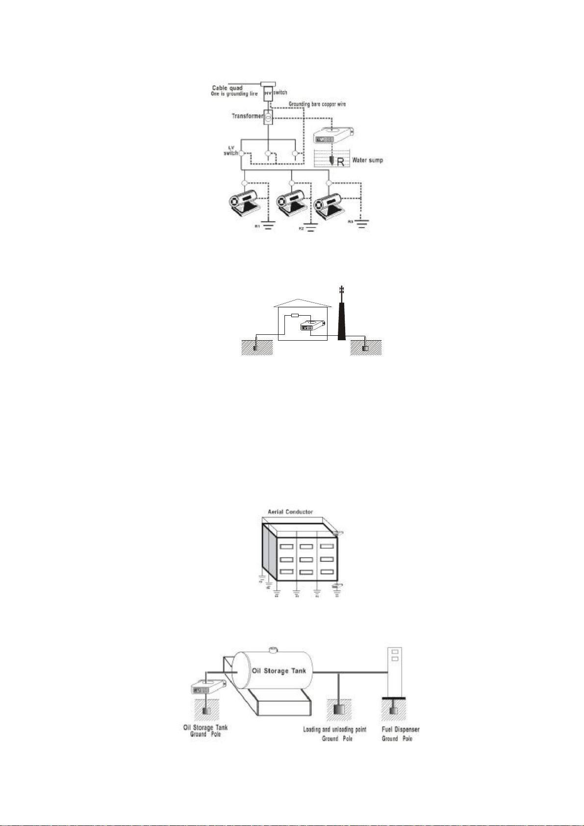
Non-ContactGroundingResistanceOnline Detector appliestoelectrictransmission line poleground
connection, underground mine device groundconnection,Meteorologicallightning protection ground connection,
petrochemicalengineering ground connection,communication groundconnection, rail facilityground connection,
building the warehouseground connection, electricalequipmentground connection etc..
II. ModelDifference
Model Difference Explanation
ETCR2800B Detectorwithoutdisplay,userneedstodosecondarydevelopmentaccording tooffered
RS485 communication protocol, to monitorthe detection data.
ETCR2800C DetectorownsLCD display,Alarmsetting, audibleandvisualalarminstructionsand
can be independentinstallation and use, andalsodoessecondarydevelopment
according to offered RS485 communication protocolandorganizesa network.

4
III. TechnicalSpecifications
Function Returncircuit grounding resistance on-line monitoring, metalreturn
resistance connection online monitoring, grounding condition monitoring.
PowerSupply Detector: DC6V DC9V,50ma Max.
Resistance Range 0.01Ω200Ω
Resolution 0.001Ω
Indication Range 0.00Ω500Ω
Accuracy ±2%rdg±3dgt(20 ±5, below70%RH)
Grounding Wire
Perforation Size
60mm×30mm,closed mode (60mm×4mmsteelflatorexternal
diameterФ30mmelectric cable)
OverflowIndication When showvalue isbeyond 500Ω, systemssoftware and LCD show “OLΩ”
sign.
Connecting Line Aonemeterlong wire(5coresshielded wire)
Connection Identifier
Red/brown---powersupplyinputanode;
Black---powersupplyinputcathode;
Blue---RS485 signalanode;
Grey---RS485 signalcathode;
White---analog grounding (powersupplyinputcathodecanconnectswith
analog grounding byshort circuit connection)
ProtocolStandard RS485 standard MODBUS-RTU communication protocol
AlarmIndication ETCR2800C:DetectorAudible and visualalarminstructions
AlarmSetting ETCR2800C:Detectorpanelsetting
DataDisplay ETCR2800C:4digitsLCD directindication
LCD Dimensions 47mm×28.5mm
DetectorDimensions 175mm×170mm×130mm
Installing ScrewHole Size
Φ8mm
Quality Detector: 960g
Working TemperatureAnd
Humidity -20 55 ;20%RH 90%RH
Humiture Error Within 5%
Shift Automatic shift
GNDInterference CurrentProhibited
ExternalMagnetic Field <40A/m
ExternalElectric Field <1V/m
SingleMeasurementOf
Time About0.5 second
PowerConsumption Detector: 50ma Max.
Installation Grounding wire through Detectorcentre bore
LevelOfProtection IP65
Installation Requirements Avoid rain and waterlogging
PowerSupplyMode Externalpowersupply(Equipped byuser)

5
IV. DetectorStructure
1.Grounding wire perforation size:60mm×30mm.
2.LCD displayer.
3.Up and downcoverconnecting screws(6 pieces).
4.Installscrewholes.
5.Button and the indicatorlight.
6.Powersupply, RS485 communication interface.
PowerSupplyIndicatorLight Working indication when powersupplyswitcheson.
AlarmIndicatorLight Alarmlightswitcheson when measured value isbeyond pre-set
criticalvalue.
SETKey Entersetup
Up and DownArrowKey Press SETkeytoenterthe alarmsetting, press up and downarrow
keyto setvalue.
EnterKey Aftersetting up alarmcriticalvalue, press ENTER keytoensure
saving.
Note: ETCR2800B mode withoutLCD displayand press keyfunction.
V. NetworkStructure
1. IndependentInstallation and Use.
ETCR2800C can be installed and used independently,alsocan develop systemsoftwareon their own
according tooffered RS485communication protocol,organizesanetworkmonitor.LCD showsmeasured value
directly,alsosetsup Detector salarmcriticalvalue, and possess audibleandvisualalarming function. When
independentinstallation itcan use2batteriesinstead ofpowersupply,orusesolarcell paneltocharge batteries,
batteriesneed placing in the protection box.
2. Reference ofNetworkOrganization.
Users candevelop systemsoftwareon their ownaccording tooffered communication protocol,organize
wired network, asthe picturebelow.
CableNetwork SystemWireless Network System

6
VI. The Principle and Application ofDetection
1. Testing Principle.
Non-ContactGrounding Resistance Online Detector’sfundamentalismeasuring returncircuit resistance.
firstlySensorsendoutadrivepulsesignaltobe measured ground returncircuit,then measured groundreturn
circuit responsesapulseelectromotiveforce E,underthe influence ofelectromotiveforce Etherewill generate
currentIinthebemeasured groundreturncircuit.SensormeasuresEandI,andimmediatelygetsresistance ofbe
measured ground return circuit through the formula:R=E/I.
2. ReturnCircuit Resistance Definition.
Aspicture:returncircuit isacompositevalue includesAspotgroundingresistance,grounding downlead
metallicconductor sresistance, metaloverhead line sresistance, connection resistance(contactresistance)between
groundingdownlead and metaloverhead line, Bspotgrounding resistance.Forthe formativeabove-mentioned
returncircuit sgroundingsystem,Detectorcan be installed directlyformonitoring, if the grounding systemnot
formareturncircuit,it needaddingauxiliarygroundingelectrodetoformareturncircuit,furtherinstall the
Detector,see the after-mentioned singlepointgroundingsystem.Ifthe Detectormeasured outreturncircuit s
compositevalue ofgrounding networkAand grounding networkBis5.0Ω,thatis:RA+RB+RC+RD=5.0Ω(RC
and RD respectivelyrepresentresistance ofmetaloverhead line and groundingdownlead ),actualgrounding
resistance value ofgroundingnetworkAand grounding networkB sinparallelresistancesless than orequalto
2.5Ω,accordinglyjudge actualgrounding resistance value ofgrounding networkAand groundingnetworkB
parallelconnection whetherqualified. Ifgrounding networkAand grounding networkB sinparallelresistances
less than engineering standard required value, so grounding networkAand groundingnetwork Bareall qualified.
3. MetalReturnCircuit Connection Resistance Testing.
Ifgrounding networkAand grounding networkBup anddownareconnected togetheron the ground, then
Detectormeasuresoutmetalreturncircuit resistance svalue isverysmall generalspeaking, onlyfewofan Ohm,
thisisthe connection resistance ofmetalreturn circuit, namelyequipotentialresistance, isn tgrounding resistance.
Therefore the Detectorisalso convenientto testmetalreturn circuit sconnection resistance.
Inthe large-scalegrounding grid, such asconverting station ground connection, oil depotground connection,
building construction groundconnection andsoon, they areallan integrallarge-scalegrounding gridunderthe
ground, meanwhiletherearemanygrounding downleadextendstothe ground, andconnectsthe otheron the
ground,asthefollowing picture. Tosuchlarge-scalegrounding grid, itsgroundinggrid smaximumdiagonal
distance isabouta fewhundred meters to thousandsofmeters, testing itsgrounding resistance isverydifficultand
troublesome. Ifitexistunqualified groundingresistance,thatproblemisappearingatthe connection position of
grounding downlead and grounding grid(direction ofarrowofthe welding position inthe picture),engineering
reformistoexcavategrounding downlead sposition, then againweldgroundingdownlead.Actuallyit s

7
impossibletoreformthe wholegroundinggrid, orthe wholegrounding gridand surface facilitiesneed topull
down and rebuild, thisisimpossible.
Therefore, forthe large-scalegrounding grid, wecan install Detectoron the primarygrounding downlead
and secondarygrounding downlead tomonitorconnection statusbetween the grounding downlead andthe
grounding grid, judge the grounding downlead sgrounding conditionsbytesting metalreturncircuit connection
resistance.
4. SinglePointGrounding System.
Ifgrounding networkAand grounding networkBiswithoutoverhead line, and doesn tconnecttogetheron
the ground,then groundingnetworkAand groundingnetworkBcanregardasstandalone singlepointgrounding
connection.Detectorcannottestsinglepointgroundingsystem sgrounding resistance directly.Thismomentit
needsadding one ormoreauxiliarygrounding electrode, toformmultipointreturncircuit,then toinstall Detector.
In the small range, if there are two ormore single pointgrounding system, it can use metallic conductorto connect
all singlepointgrounding system sgrounding downlead togetheron the ground, toformareturncircuit,then
install the Detectorto monitor.
5. Application.
(1).PowerTransmission SystemPole Ground Connection.
Itforms multipointgrounding systemthrough overhead groundwireconnection;testconveniently,its
equivalentcircuit asthe following picture on the right.
illustration:R1ispredicted grounding resistance, R0isthe equivalentresistance ofall the otherpole s
groundingresistance parallelconnection, thatisR0=R2∥R3∥R4∥…∥Rn,if the greaternis(themoregrounded
junction),the closerR0getsto0,farsmallerthan R1,fromengineering pointofview,R0=0,so, the dataDetector
receivesshould be R1svalue.
(2). Underground Mine PowerTransformation Ground Connection.
respectively,primarygrounding electrode R,R1R3…Rnisa independentgrounding bodyunderthe ground,
don tconnecttogether,aremultipointgrounding system,convenienttotest.Detectorisinstalled on the primary
grounding electrode, the Detector sindication isR
r
=R+R1∥R2∥R3∥…∥Rn.Ifthe morepart grounded
junctionsare, soR1∥R2∥R3∥…∥Rn≈0,then Rr=R.It sthe four-code cableinthepicture, onecodeisground
lead among it,all the devicesandpart grounding connection areconnected tobeanetworkbycablegrounding
connection, dotted line isbare copperwire ofgroundingconnection.

8
(3). GeneratorRoomand Launch TowerGrounding Connection.
GeneratorRoomand Launch Towerisindependentoutdoors generally,connectbothtogethertoformsecond
return circuit, then install detector, asthe picture below.
(4). Construction Grounding Connection.
IfR1
R6
…Rn
isaindependentgrounding bodyunderthe ground, don tconnecttogether,aremultipoint
groundingsystem,convenienttotestgrounding resistance. IfR
1
R
6
…R
n
areconnectedtogetherunderthe
ground,forthesinglepointgroundingsystem,testinggrounding resistanceinaccordancewithsinglepoint
grounding system, directinstallation testreturn circuit resistance, can judge groundingconnection condition.
Forthe large-scaleconstruction groundinggrid,it istomonitoritsequipotentialvalueofgroundingcondition
between grounding downlead and grounding network.Ifproblemsoccur,it wouldbe located attheconnection
pointbetween groundingdownlead andgroundingnetwork, and judging thatwhetheritsequipotentialvalue
qualified ornot.
(5).Oil Storage Tank sloading and Unloading PointGrounding Connection.

9
VII. Wiring Instructions
Wire Color Introductions
Red/Brown PowerSupplyAnode
Black PowerSupplyCathode(GND)
Blue RS485 SignalPositive Electrode
Grey RS485 SignalNegative Electrode
White Signalgrounding electrode can short connectGND.
When organize a network, it needsconnecting Detectorinaccordance with wire color.
VIII. Install Caution
SpecialExplanation:onlyifit forms areturncircuit grounding connection system,it coulddirectlyinstall
and use.Otherwise, firstlyitneedstosetupanauxiliarygrounding connection nearbytoformareturncircuit,
then to install the Detector.
1. Install the Detectortogrounding downlead, andgrounding downlead needstounbucklebuckle,
convenientforproductmaintenance latterly.Installation mustbe waterproof,rainproof,anti-theft and
breakage-proofand so on inthe open air.
2. Notice direction, tryto be verticaland wire port downwards.
3. Notice height.
4. Deploypowersupplyand communication wire on the basisoffield and distance.
5. Powersupplywire spolaritiesconnectproperlyorDetectordoesn twork.
IX. Power SupplyWayChoice
1. ACadapterconverts powersupply s220VACinto 6-9VDC, which can supplyDetector.
2. 2 piecesstandbybatteriesforalternate use.
3. Asthe picturebelow,solarcell panelsupplyissuitableforthe placeswherecan'tgetelectricity.Solarcell
panel sanode and batteries anode needsafastrecoveryrectifierforwardconnection inseries(asIN5817),when
using ETCR2800C isconvenient.
X. Basic Equipment
Detector 1Set
ConnectorWire 1PCS
Packing Box 1 Set
User'sManual,WarrantyManual, Certification 1 Set

10
This manual suits for next models
1
Table of contents
Other ETCR Measuring Instrument manuals