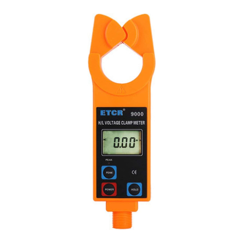
ETCR 9200 User manual


CONTENT
Warning.................................................................................................1
. BriefIntroduction.............................................................................3
III.SeriesModel..................................................................................4
IV.TechnicalSpecification..................................................................5
V. Structure...........................................................................................7
VI.LCD Display...................................................................................8
VII.Operation....................................................................................10
A. TesterOperation...........................................................................10
1. PowerOn/Off..............................................................................10
2. GeneralTest................................................................................ 11
3. PEAKTest...................................................................................13
4. DataMaintenance.......................................................................13
5. DataMemory..............................................................................13
6. DataReference...........................................................................14
7. DataDeletion..............................................................................14
*8. DataTransmission.....................................................................14
B.Operation ofReceiver..................................................................14
1. PowerOn/Off...........................................................................14
2. DataReception...........................................................................15
3. DataMaintenance.......................................................................15
4. DataMemory..............................................................................15
5. DataReference...........................................................................15
6. DataDeletion..............................................................................16
VIII. ReplacingBatteries..................................................................16
IX.Accessories...................................................................................17


1
Warning
Thanks foryourpurchaseof ETCR9200 H/LVoltageClamp
CurrentMeter ofourcompany.Inordertomakebetteruseofthis
product, pleasemakesureto:
Readthismanualindetail and theoperatormust
totallyunderstand thismanualand beinproficientin
operation ofthismeterbeforemaking teston spot.
Strictlycomplywiththesecurityrules and notice
itemslistedon thismanual.
uInanycase, it shouldpayspecialattention tosafetyinuseof
thismeter, particularlyinmeasurement ofcircuitrywithmorethan
AC100Vand abovevoltages.
uIfthe voltageoftested circuitryhasexceeded 600V, it must
beused byconnectingwithan insulation rod.
uAsit isverydangerousofhighvoltagetransmission line, the
operatormustget strict trainingand the relevant certification on
high-pressureoperation ofthe statebeforeusingthismeterand
makingafieldtest.
uIt isforbidden tousethe metertestvoltagemorethan 35 kV
convergenceofbarewireorbus
uPleasepayattentiontomarked wordsandsymbolson panel
orbackboardofthismeter.
uPleasedonotputorstorethismeterinthe placeofhigh
temperature,withmoisture,withfrozen deworwithdirect
daylight irradiation foralongtime.
uPleasenotethe batterypolaritywhen replacingbattery,and
removethe batteryif youexpectnottousethismeterforalong
time.
uIt mustbeoperated byqualified staffthathasthe
authorizationon tearingdownorrepairingthismeter.
uPleasedo notuseitwhen thereisanydamageon the
transducerclamporotherpartsofthismeter.

2
uToavoidthe impactof transducerclamp,itneedstomaintain
thismeterregularly. Donotusecorrosiveorcoarsematerialsto
clean,butusesoft cloth(suchasglassescloth),dippingclean
anti-rustdesiccantlubricant(suchasWD-40),and makinga
gentlewiping.
uForthe reason ofthismeter,incasethatanydangermay
occurifcontinue touseit, stopusingitimmediatelyand sealit
upforkeepingatonce,whichshall bedealtwithbyqualified
authorizationagency.
uThe dangersymbol on the meterand the manual,the
usermustmakesafeoperation accordingtothe indication.
uThe extremelydangeroussymbol ”, the usermust make
safeoperation accordingtotheindication.
uIt suggeststhatthismetershall bemade insulation intensity
test atleastonceannually.(AC100kV/rms 5sectionsinsulating
rod allconnections, betweenbothends)
uAstothe partwith *”markinthismanual,itisonlylimited to
ETCR9200B (wireless Transmission data).

3
. BriefIntroduction
ETCR9200 Series H/LVoltageClampCurrentMeter hasbroken
throughthetraditionalstructure,whichisspeciallywell-designed
formeasuringhighvoltagecurrent, adoptlatestCTtechnology
and integrated mask digitaltechnology,composedofspecial
clampcurrentmeterand highvoltageinsulation rods.Without
insulation rods,itcan used ashigh-precision low-voltageclamp
meterand leakage currentmeter,can accuratelymeasurethe
current orleakagecurrent of0.01mA.
ETCR9200 Series H/LVoltageClampCurrentMeter adopt
hooktypestructureof innovation,whichcan hooktheline totest,
savethe physicalpowerofuser,toensurethe highprecision ,
highstabilityandhighreliabilityofperennialuninterrupted
measurement.
ETCR9200SeriesH/LVoltageClampCurrentMeterconnected
withinsulation rod,canbeusedtomeasurethehighvoltage
currentofthe cableunder 60KV (withan insulating).orbarewire
cable(≤35kV ).on-line currentmeasurement, alsohavingpeak
maintenance,datapreservation,datastorage,wireless
transmission and otherfunctions.anditsspecial ClampLeaker
can makeiteasierforclampingorevacuatingthe tested wire
throughpressingorpullingback the insulation rod,time-saving
and fast, widelyusedintransformersubstation,powerplant,
industrialandminingenterprisesaswellastheinspection station
and electrician maintenancedepartmentsforelectricalcurrent

4
detectionand fieldelectricaloperations.It can alsoreplacethe
H/Lvoltagetransformingratiotester,thatis,todetectthehighand
lowcurrentforprimarycircuitand secondarycircuitseparately,
and thencalculatetoconclude thechangeofhighand low
pressure.The insulationrod islightand convenient, withthe
advantagesofanti-moisture,hightemperatureresistance,
anti-impact, bendingresistance,highinsulation,flexibilityand
othercharacteristics.
II. Electrical Symbols
ExtremelyDangerous!The operatormust strictlyabide by
the safetyrules. Otherwise, thereiselectricinjurydanger,
causingpersonaldamageorcasualtyaccident.
Dangerous!Theoperatormust strictlyabide bythesafety
rules.Otherwise,thereiselectricinjurydanger,causing
personaldamageorcasualtyaccident.
Warning!It muststrictlyabidebythesafetyrules.
Otherwise,itmaycausepersonaldamageorcasualty
accident.
AlternatingCurrent (AC)
Direct Current (DC)
III.Series Model
Model Rangeof
measurement
Accuracy
Jaw
Specification
Description
ETCR 9200 0.00mA-1000
A 0.01mA Φ68mm Base
ETCR 9200B
Wireless

5
IV.Technical Specification
Function
HighvoltageACcurrentmeasurement, low
voltageACcurrent, leakagecurrent
measurement, on-line ACcurrent supervision.
PowerSupply
DC6VAlkaline DryBattery(1.5VAAAX4)
TestMethod
ClampCT, IntegralMethod
*Transmission
MethodETCR9200B433MHzWireless Transmission
*transmission
distance 30m
Clampsize φ68mm
Rangeof
measurement 0.00mA~1000A(50Hz/60Hz
AutoIdentification)
Resolution 0.01mA
Shift 0.00mA~1000AAutomaticShift
TestAccuracy
(23 ±5,
80%RH)
0.00mA~299mA:±1%±3dgt
300mA~49.9A:±1.5%±5dgt
50.0A~199.9A:±2%±5dgt
200A~600A:±3%±5dgt
601A~1000A:±4%±5dgt
Sampling Speed
About 2times/second
Display Mode
4digitalLCD display
LCD Dimension
TesterLCD:35mm×21.5mm
ReceiverLCD:47mm×28.5mm
MeterDimension
Tester:218mm×135mm×60mm
Receiver:170mm×75mm×30mm
DataStorage 99 Groups,duringstorage,thesymbol MEM”
givesindication, FULL”markwill flashto
indicatethememoryhasbeen full.

6
Peak
Maintenance
Automaticallymaintainthe heightofthe tes
tvalue,usuallyinthe testmode press PE
AK key,LCD top rightcornerwilldisplay “PE”,
thatis,tokeepopen thePEAK function,th
en press PEAK keytocancelthisfunction
CircuitVoltage Testinsulatingsheathwires(≤60kV )orbare
wiret(≤35kV )(operated withinsulation rod)
Data
Preservation
Undergeneraltestmode,press HOLD button
topreservedata, DH”symboldisplay.then
press HOLD Keytocancel( HOLD”symbol
display)
DataAccess MR ”symbolindicates,itcan read the stored
databyturningupwardsand downwards.
OverflowDisplay
Exceedmeasurementrangeoverflowfunction:
OLA”symboldisplay
*
Nosignal
Indication When the receiverhasnotreceived transmit
signal, itwilldisplay no--”symbol
AutoShutDown
About15minutesafterbooting,themeterwill
shutdownautomatically,inordertodecrease
the batteryconsumption.
BatteryVoltage When the batteryvoltageisbelow4.8V,the
symbolofbatteryvoltage ”will showto
remind toreplacebattery.
Weight
Tester:About 620g(Includingbattery)
receiver:About 220g(Includingbattery)
Totalqualityofmeter:about2.3kg(including
insulation rod and battery)
Work
Temperatureand
Humidity -10 ~40 ;≤80%Rh

7
Storage
Temperatureand
Humidity -10 ~60 ; ≤70%Rh
Interference Avoidsamefrequencyinterfere(315MHz&
433MHz)
InsulatedRod
Dimension φ32mm, 1m/ Section(5Sections)
Insulation
Intension
Tester/receiver:AC2kV/rms(Between coreand
shell)
Insulatingrod:AC100kV/rms(5sections
insulatingrod all connections, between both
ends)
Structure Anti-DrippingTypeII
V. Structure
1. Insulatingrod connectinghead
2. clamp(boot sector)
3. LCDdisplay
4. PEAK key(start LCD display PE”)
5. HOLDkey
6. POWER key
7. POWERlight
8. Insulatingrod (5sections)

8
testtest(wireless)receiver
VI.LCD Display
1.Explanation forSpecial Symbols
⑴.Lowbatterysymbol,when the voltageofbatteryis
lowerthan 4.8V,thissymboldisplay,pleasereplacebattery
intime.
⑵.OLA”Thissymbolindicatesthatthecurrentontesthas
exceededthemaximummeasurement limit ofthe meter.
⑶.MEM”Memorymode,itwill displayduringthedatastorage
process.
⑷.Full”symbol,when the storagememoryhasbeen filled
with99 groupsofdata,itwill display FULL”symbolby
flash,whichmeansit cannot continue tostoredata.

9
⑸.MR”dataaccess symbol,whichisdisplayed duringlooking
updata, meanwhile, itwilldisplaythe serialnumberofdata
instorage.
⑹.End”exit symbol, itwill displayduringthe exit.
⑺.dEL”datadeletesymbol, itwilldisplaywhen deletingdata.
*⑻.no--”None received signalinstructions,dynamicdisplay,it
maynotintestmode,oradjustthe location anddistance
fromreceiver.
(9). PE”symbol,press PEAK”display,IndicatesstartPEAK
test.
HOLD”, DH”symbol,press HOLD”display,lock the data.
2.Display Demonstration
⑴. ——The current on test
is0.002A(2mA)
⑵. ——Locked displayData
——The dataisautomatic
stored asgroup3
——The current on test is: 160.5A
⑶.——The current on test is: 571A
——Lowbatterysymbol
pleasereplace.
⑷.——Lookupdataofgroup3instorage
——The current on test is: 160.5A
⑸.—— FULL”flashdisplay:
Storageisfull of99 groups

10
——It can’t storemoreunless
deletestorage
⑹.——“dEL”Indication ofdatadelete
⑺.—— End”Indication ofexit
*⑻.—— no--”Dynamicdisplay: none
received signal
VII.Operation
Pleasecheck all partsof the metercarefullybefore
usage,toseewhetherthereisanydamage.And
makesureno damagebeforeusage.
Accordingtomanualinstructionstoinstall the
battery
A. TesterOperation
1. PowerOn/Off
Press POWER button topoweron, the instrument will displaysthe
LCD screen,enteringnormaltestingmode.IfLCD displayis
relativelydarkafterpoweron, it ispossiblethat batteryvoltageisa
bitlower.Pleasereplacebattery.15minutesafterpoweringon the
meter,ifitremainsidle,an auto-poweroffprocedurestartsto
preservethe batterylifeand LCD will continue flashuntil the
completeswitchofftakesplaceafter30 seconds.IncaseofLCD
continuousflash,press POWER button,then the meterwill
continuetowork.
UnderHOLDmode, press POWER button forpoweroff.
Undergeneraltest mode, press POWER button topoweroff.

11
Under PEAK testingmode,press POWE button topoweroff.
Underdatareferencemode, firstlypress POWER button formore
than3secondstoexitfromdatareferencemode,returningto
normaltestmode,thenpress POWER button topoweroff.During
the exit fromdataaccess, it will display End”symbol.
2. GeneralTest
Highvoltage,extremelydangerous!It mustbeoperated
byqualified staffthathasacquired authority. Theoperator
must strictlyabide bythesafetyrules. Otherwise, thereis
electricinjurydanger,causing personaldamage or
casualtyaccident.
uDangerous! It isforbidden tousethemetertest
voltagemorethan 35 kVconvergenceofbarewireor
bus. Otherwise,thereiselectricinjurydanger,causing
personaldamageorequipment damage.
Dangerous!It cannotbeused tomeasurethe circuit over
600Avoltage.Otherwise,thereiselectricinjurydanger,
causingpersonaldamageorequipment damage.
GeneralTest: Inthe process oftest, LCD willdisplaythe tested
currentvalue realtime,andLCD datawill varywiththecurrent
change. When thetesterisremoved awayfromthe lead on test, it
doesnot preservethe test result, LCD displaywill returntozero.
Innormaltestingmode,itissuitableforclosedistance
measurement, convenientforcircuittestbydirectread ofLCD
data.

12
Beforetest,firstlytoconnectinsulationrod,which
mustbeconnectedinrightposition,andthento
connecttester,avoidingthe impactof metertoground
surface.
Makesuretousespeciallyequipped insulation rodto
connect withthe meter.
Aftertest, itshouldincline theinsulationrod
accordinglyon drawingin.Firstlytoteardownthe
testerandthentheinsulationrod, avoidingthe impact
ofmetertoground surface.
Afternormalboot,placethe leadinthemiddleof clamptransducer
domain, The drop-downinstrumentclamped conductortobe
tested,showingtheresultonLCD display.Ifshowing "OLA",it
meanstheleadcurrentontesthasexceededthe maximum
volumeon the level.Pleaseselectahighergearlevelorameter
withgreatermeasurementlimit. Pushthe instrumentcan be
evacuated beforeconductortobetested

13
Under HOLD mode,press HOLD button tocancelHOLDfunction,
and returntonormaltestingmode.
Underdatareferencemode, press POWER button formorethan 3
secondstoexitfromdatareferencemode,returningtonormal
testingmode.
Under PEAK testingmode,press POWER buttontoexitfrom
PEAK testingmode, returningtonormaltestingmode.
Afterdatadeletion,itwillreturntonormaltestingmode
automatically.
Attention!Forthe sakeofsafety, when test hasbeen
finished,pleaseremovethe meterawayfromthe
lead ontest
3. PEAKTest
PEAK test: the maximumcurrenttest. the meterwill make
automaticcomparison on thechangesinmeasured current,
indicatingthe maximumvalue and maintainit, when the meteris
removed awayfromthe leadontest, thetestresultwill bekept
consistently,suitableforthe circuitteston thoseLCD datahardto
beread directly
Underthe normaltestingmode,press PEAK button,LCD display
PE”,enterPEAKtestingmode.That meansthe meterwill display
and automaticallykeepthemaximumvalue inthe test.
Underanyothermode,itmustbereturnedtonormaltestingmode,
and then makePEAK testingaccordingtotheaboveoperation.
Press POWER button toexitfromPEAK testingmode,returningto
normaltestingmode.
4. DataMaintenance
Undernormaltestingmode,press HOLD button tokeepLCD
display.Press HOLD button againtoreleasedatalock,returningto
normaltestingmode.
5. DataMemory
Undernormaltestingmode,press HOLD tostorage data,atthe
sametime,Meterwillautomaticallyformserialnumbers,and
memorythe currentpreserved data.Thismetercan memory99

14
groupsofdata,incaseoffullstorage, FULL”symbolwill display
byflashcontinuously,anditcannotcontinuetomemoryuntil
cleaningout the previousmemory.
6. DataReference
Undernormaltestingmode,press PEAK + POWER button to
enterdatareferencemode, meanwhile,it willautomaticallydisplay
datasaved inthegroup01.Thenpress PEAK or POWER button
toread the stored databyturningupwardsordownwardsincycle.
It willreturntothe group1’sdataautomaticallyafterreachingthe
last group’sdatainstorage.
Press HOLD button toexitfromdatareferencemode,returningto
normaltestingmode. Duringthe exit, it will display End”symbol.
7. DataDeletion
Underdatareferencemode,press PEAK + POWER button to
deleteall thedatainstorage,and returntonormaltestingmode.
Duringthe deletion ofdata, it will display dEL”symbol.
*8. DataTransmission
ETCR9200B: hasthefunctionofwireless datatransmission.
When the Meterundertestingmode,the testresultwillbe
transferred toreceiverbywireless transmission andthe receiver
will displaytest result realtime, beingclearat aglance.
Onlyundertestingmode,the meterwill transmit, Ifthe receiverhas
notreceived emission signals,itwill display no--”symbol
dynamically.
BType: Transferred
ETCR9200B: Wireless transmission testdata,astraight-line
distanceofabout30 meters,can penetratethe floortoreceive
data.
B.Operation ofReceiver
(Note: ForETCR9200Bonly)
1.PowerOn/Off
Press POWER button topoweron, the instrument will displaysthe
LCD screen,enteringnormaltestingmode.IfLCD displayis
relativelydarkafterpoweron, it ispossiblethat batteryvoltageisa

15
bitlower.Pleasereplacebattery.15minutesafterpoweringon the
meter,ifitremainsidle,an auto-poweroffprocedurestartsto
preservethe batterylifeand LCD will continue flashuntil the
completeswitchofftakesplaceafter30 seconds.IncaseofLCD
continuousflash,press POWER button,then the meterwill
continuetowork.
Under HOLD mode, press POWER topoweroff.
Underdatareference,first, press POWER button(for3seconds)
toexitdatareferencemode,then comeback todatareceivemode,
press POWER button onceagaintopoweroff.Duringexitfrom
datareference, it will displaythe symbolof End”.
2. DataReception
Afternormalpoweron,the receiverwill underreceivingmode.If
thereareemission data, thereceiverwill displaythe test result real
time.Ifithasnotreceived anysignal,the receiverwill search
signalsconstantly, anddisplay no--”symboldynamically.
3. DataMaintenance
UnderDataReceptionmod,press HOLD button,keepLCD
display, HOLD”symbolindication.Press HOLD button once
againtorelievedatalock,returntodatareception mode, HOLD”
symboldisplay.
4. DataMemory
UnderDateReception mode,press HOLD button tomaintaindata,
meanwhile,the receiverwill automaticallyformserialnumbers,
andmemorythecurrentpreserved data.During thestorage,
MEM”symbolwill displayoncebyflash.Thereceivercan memory
99 groupsofdata,incaseoffull storage, FULL”symbolwill
displaybyflashcontinuously,anditcannotcontinue tomemory
until cleaningoutthe previousmemory.
5. DataReference
UnderDataReception mode,press HOLD+POWER button to
enterDataReferencemode, MR”symboldisplay,meanwhile,it
will automaticallydisplaydatasaved inthegroup1.Thenpress

16
HOLD button or POWER button toreadthestoreddatabyturning
upwardsordownwardsincycle.It willreturntothe group1’sdata
automaticallyafterreachingthe lastgroup’sdatainstorage.
Press POWER button formorethan 3secondstoexitfromdata
referencemode,returningtoreceivingdatamode.Duringthe exit,
it will show End”symbol.
6. DataDeletion
Underdatareferencemode,press HOLD + POWER button to
deleteall the datainstorage, andreturntoDataReception mode.
Duringthe deletion ofdata, it will display dEL”symbol.
VIII.ReplacingBatteries
Warning!Incasethatthebattery’scoverboardisnot
wellclosed,itisforbidden tomaketest. Otherwise,itis
dangerous.
Payattention tothe polarityofbattery,incaseof
damagetothe meter.
Donot mixinthe useofnewand oldbatteries.
1.When the batteryvoltageisbelow4.8V,themeterwill display
” symbol,indicatingthe batterieshaveno sufficient
powercontent. Pleasereplacebatteries.
2.Poweroff, tomakesurethe meterisunderthestateofpower
off.Toloosentwoscrewsofthe batterycoverboard, open the
coverboardtoreplacebrand-newqualified batterieson.It
shouldpayspecialattentionon the batteryspecification and
polarity, coverthe boardwell and fasten the twoscrews.
3.Press POWER button tocheck whetherthe metercan be
powered on normally.Ifnot, pleaserepeattheoperation
accordingthe step2.
This manual suits for next models
1
Table of contents
Other ETCR Measuring Instrument manuals
Popular Measuring Instrument manuals by other brands

Promax
Promax MZ-505C user manual

B+K precision
B+K precision BK603B user manual

In-situ
In-situ RuggedReader Operator's manual

Electronics International Inc
Electronics International Inc M-1 Operating and installation instructions

Microgate
Microgate RACETIME 2 manual

foc.us
foc.us Firestore FS-100 quick start guide