ETI NETCOM ADH Use and care manual
MODEL ADH
ADH NETCOM AUTOMATIC AIR DEHYDRATOR
AC POWER SUPPLY MODULE REPLACEMENT PROCEDURE
Replacement Kit Part Number 24094
Document Part Number 24106

AC POWER SUPPLY MODULE
REPLACEMENT PROCEDURE
MODEL ADH
Lethal Voltages Present
Lethal voltages are present inside the ADH
NETCOM. Service should be performed by
qualified personnel only. There are no user
serviceable components inside the chassis.
Abnormal Odor or Smoke
In the event of smoke or a burning or abnormal
odor, immediately interrupt power to the ADH
NETCOM with the POWER switch at the rear of the
unit, unplug the unit, or turn off the circuit breaker
controlling the outlet. Note that only the AC model
of the ADH NETCOM has an ON / OFF switch.
Pneumatics
Each of the air pumps inside the ADH NETCOM
automatic air dehydrator is capable of generating
as much as 24 psig (1,655mbar). Other attached
dry air sources may be capable of generating even
higher pressures. Proper safety practice requires
treating all pneumatic components with care.
Always vent the system to atmospheric pressure
before servicing pneumatic components.
Rack Mounting
Before and after rack mounting the ADH
NETCOM, ensure that the rack is stable. Mounting
of the ADH NETCOM into a rack should be such
that a hazardous condition is not created due to
uneven mechanical loading. Verify that adequate
air flow and power source capacity is available to
the unit. Ensure that the ADH NETCOM maximum
operating temperature of 130°F (55°C) will not be
compromised by other components in the rack.
Ensure reliable earthing of the ADH NETCOM.
ADH NETCOM HUMIDITY SENSOR ASSEMBLY
REPLACEMENT PROCEDURE
This procedure addresses the removal and replacement of
the AC Power Supply Module in an ADH NETCOM Automatic
Air Dehydrator with AC Power. It is recommended to read
the entire procedure prior to beginning work.
INVENTORY LIST
Identify the following items in this kit prior to beginning
work.
TOOLS REQUIRED
The following tools are needed to perform this procedure:
• Needle nose pliers
• 5/16” Nut driver
• Philips screwdriver
2
PART NO. DESCRIPTIONQTY.
23450
24106
Humidity Sensor Assembly
Instruction Manual (this document)
1
1
AC POWER SUPPLY MODULE REPLACEMENT PROCEDURE | PART NO. 24106 REV B.0
3
Shut off machine power by placing power switch in the OFF
(O) position. With the power switch in the off position,
unplug the power cord. If possible, move the dehydrator to
a work table.
Remove both top machine panels. Retain the mounting
hardware.
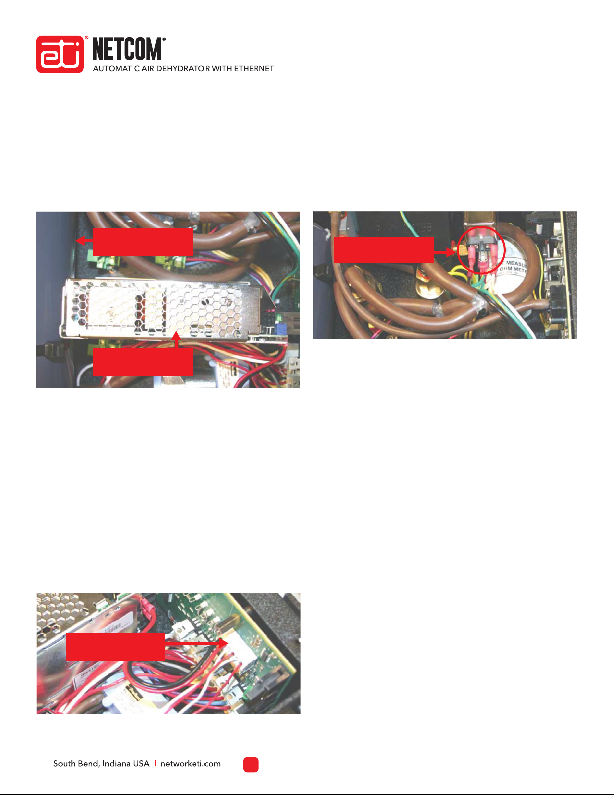
Disconnect the two wires (red and black) running from the
AC power supply module to the terminal block on the PC
board. Refer to Figure 2. Using a small screwdriver, press in
on the orange release tab under the lead then gently
remove the lead. Repeat for the other lead.
To replace the AC Power Supply Module (23450) in an ADH
NETCOM with AC power, perform the steps below. Refer to
Figure 1.
AC POWER SUPPLY MODULE REMOVAL AND
REPLACEMENT
1.
2.
3.
Using a needle nose pliers, carefully disconnect the three
leads (white, black, and green/yellow) running from the AC
power supply module to the back of the power filter
module. Refer to Figure 3. To avoid damaging the leads,
hold the leads by the spade lugs, not by the wires.
4.
Using the 5/16” nut driver, loosen and remove the two nuts
and lock washers securing the existing AC power supply
module to the chassis. Refer to Figure 4. Retain the
mounting hardware.
Once all five AC power supply module leads have been
disconnected and the mounting hardware removed, take
the existing AC power supply module out of the dehydrator.
Install the new AC power supply module in the same place
from which the original module was removed. Secure the
module in place using the two nuts and lock washers
removed in step 5. Torque to 5.5 in/lb.
Install the set of three leads (white, black, yellow/green) to
the terminals from which the original leads were
disconnected on the back of the power filter module in step
4. Connect them as the similar colored leads had been
connected originally: the black lead on the left, the white
lead on the right, and the yellow/ green lead in the middle.
Connect the set of two leads (red and black) to the same PC
board terminal block locations from which the original
leads were disconnected in step 3. Connect them as the
similar colored leads had been connected originally: the
black lead on the left and the red lead on the right.
Reinstall the machine top panels using the hardware
removed in step 2.
Restore machine power.
5.
6.
7.
8.
9.
10.
11.
Figure 1. THE ADH NETCOM AUTOMATIC AIR DEHYDRATOR AC POWER SUPPLY MODULE.
Figure 2. THE PC BOARD TERMINAL BLOCK.
Figure 3. THE POWER FILTER MODULE TERMINALS.
AC POWER SUPPLY MODULE REPLACEMENT PROCEDURE | PART NO. 24106 REV B.0
AC POWER SUPPLY MODULE
REPLACEMENT PROCEDURE
MODEL ADH
Air Drying Canister #2
(reference)
AC Power Supply
Module
Leads from AC Power
Supply Module
Leads from AC Power
Supply Module

For technical help, questions or comments concerning this
product or any ETI product contact Customer Service 8:00 a.m. -
5:00 p.m. Eastern Time.
networketi.com
ETI
1850 North Sheridan Street
South Bend, IN 46628
Email:
Web:
Mail:
CONTACTING CUSTOMER SERVICE
ETI’s two year limited warranty covering defects in workmanship
and materials applies. Contact Customer Service for complete
warranty information.
LIMITED WARRANTY
ETI makes no representations or warranties, either expressed or
implied, with respect to the contents of this publication or the
products that it describes, and specifically disclaims any implied
warranties of merchantability or fitness for any particular
purpose. ETI reserves the right to revise this publication, and to
make changes and improvements to the products described in
this publication, without the obligation of ETI to notify any person
or organization of such revisions, changes or improvements.
DISCLAIMER
4AC POWER SUPPLY MODULE REPLACEMENT PROCEDURE | PART NO. 24106 REV B.0
AC POWER SUPPLY MODULE
REPLACEMENT PROCEDURE
MODEL ADH
Other manuals for NETCOM ADH
8
Other ETI Industrial Equipment manuals

Popular Industrial Equipment manuals by other brands

Panasonic
Panasonic CM202 Series Maintenance manual

McElroy
McElroy Hornet XL Series Operator's manual

Telesis
Telesis NOMAD 4000 manual

Dungs
Dungs GB 053 Customer's operating and assembly instructions

Global
Global WF 1767-70 Series Instruction & parts manual

Banner
Banner A-GAGE MINI-ARRAY MACNXDN-1 instruction manual


