ETI ERM Series User manual

Optional Bracket
Regular Installation L-bracket for narrow
frame (optional)U-bracket for frameless
glass door (optional)LZ-bracket for inswing
door (optional)
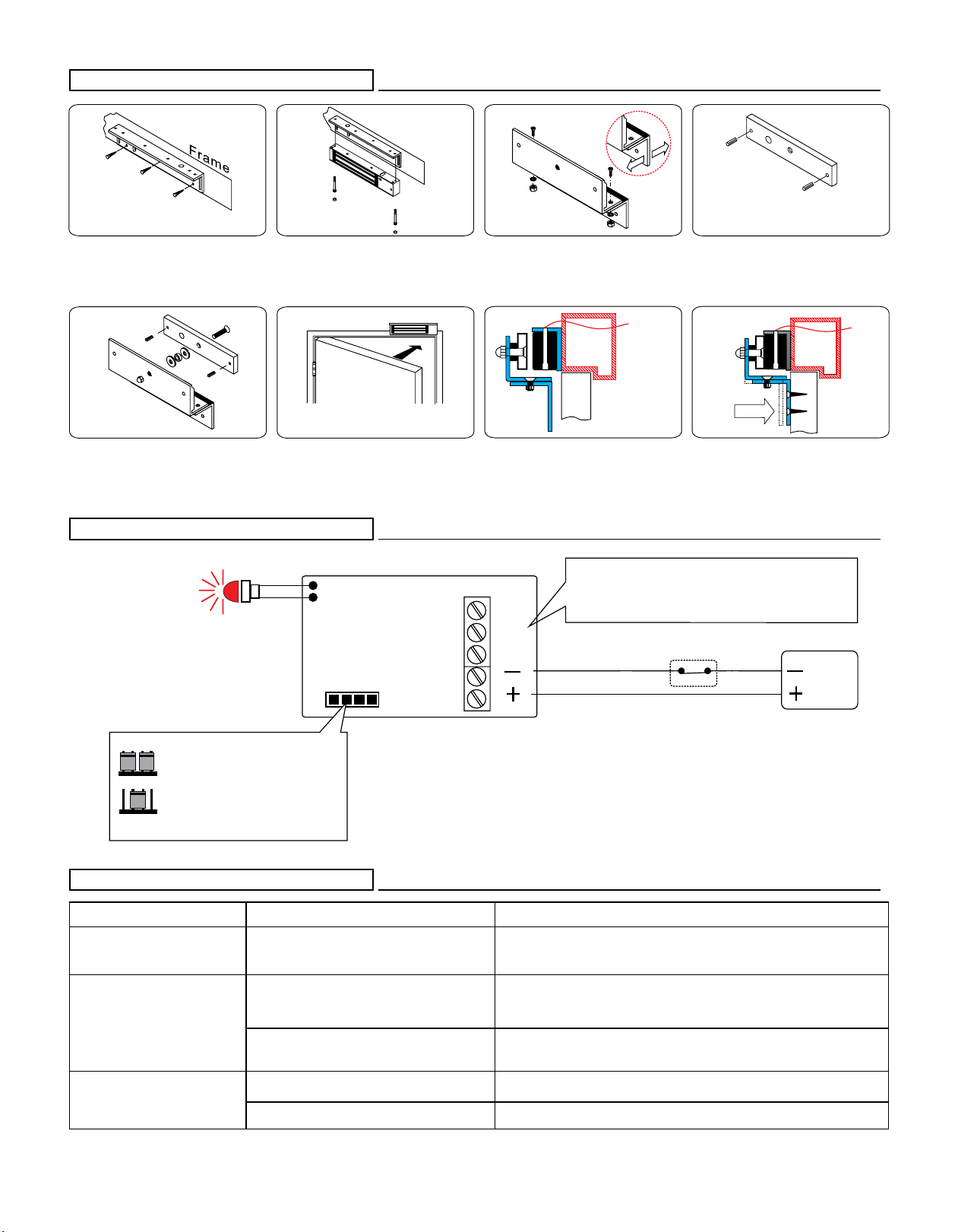
Bracket installation is according to door swing direction and door frame type ,e. g. narrow frame door , frameless glass door, inswing door , etc.
Regular Installation
1
2
3
Template
Fold the mounting template 90°.
Place the template to the proper
position of the door and frame. Mark
the hole positions of the template on
the door and frame.
Drill the holes according to the
marks.
7
Fix the mounting plate on the door
with mounting screws.
Cable
8
Use the Allen wrench and fixing bolts
to tighten the electromagnetic lock to
mounting plate.
Allen wrench
9
Connect the power and test the unit.
Outdoor
Power
6
Fasten the mounting plate with the
mounting screws. The position of the
mounting plate should be adjustable.
5
The rubber washer makes the
surface of the armature plate
adjustable in order to completely fit
the surface of magnetic lock.
Rubber Washer
(outswing door)
4
Please install the armature plate as
illustrated here. (Dimensions of the
holes are depending on the door
types as illustrated below.)
Armature Plate
3/8” 5/16”
Hollow Metal Door
3/8” 5/16”
Solid Door
1-7/16”
Outdoor
Outdoor
Drill a 5/16” hole
through door,
on closing side
enlarge to 3/8”
by a sex nut bolt
on the opening
side.
Electromagnetic Lock Installation Instruction
ERM SERIES
LZ bracket for Inswing doors
Connecting Diagram
+
+
-
-
N.O.
COM.
N.C.
Power
Input
Power
supply
SPDT relay
0.5A/125VAC
1A/24VDC
12VDC
24VDC
Voltage Selection Jumpers
Check jumper settings before
connecting the lock to 24 VDC
input power. Damage to the
lock may result from incorrect
jumper settings.
Problem Possible Cause Solution
Door does not lockNo power
Poor contact between electromagnet and
armature plate
Low voltage or incorrect voltage setting
A secondary diode was installed across
the electromagnetic lock
Misalignment between the armature plate
and electromagnetic lock
Make sure the wires are connected properly
Check that the power supply is connected and works properly
Make sure the lock switch is wired correctly (N.C.)
Make sure if the armature plate is not misaligned
Make sure the contact surfaces of the electromagnet and armature plate are clean
and free from dust
Make sure the armature plate and electromagnetic lock are aligned correctly
Make sure if the rubber washer was used between the bracket lock and armature plate
Check the electromagnet lock is set for the correct voltage.
Check the voltage at the of input electromagnetic locks. If low, determine if the
correct wire gauge is being used to prevent excessive voltage drop.
Remove any diode installed across the magnet for "spike"
suppression. (The magnet is fitted with a metal oxide varistor to prevent back EMF)
Low holding force
Sensor output is not functioning
Trouble Shooting
2
Use the fixing bolt to tighten the
electromagnetic lock on L bracket.
1
Find a mounting location on the
door frame for the L bracket. Make
sure that the door is still closeable.
6
Close the door and connect the
power.
4
Insert the guide pins into the
armature plate.
5
3
N.C. c ontact output: open s tatus
N.O. c ontact output: l ocked status
Relay r ating output needs t o meet t he i nstruction o f PCB
7Power
Outdoor
FinishPower
Outdoor
Assemble the Z bracket, and
make sure t hat the position o f the
Z bracket is a djustable.
Fasten the armature plate to the
Z bracket (Rubber washer must
be added).
After the maglock attracts the
armature plate, adjust the
position between Z bracket and
the door. Then f ix t he Z b racket.
Connect the power, close the
door a nd t est the unit.
Control Device N.C. contactor Access Relay
Bonds sensor output
Popular Lock manuals by other brands


AMSEC
AMSEC ESL15 operating instructions

Motormate
Motormate Yamaha 10-301 installation instructions

Gemini
Gemini 2700 installation instructions

Burg Wächter
Burg Wächter secuENTRY ENTRY 7710 RFID manual

Gianni Industries
Gianni Industries PBT-900 Series Specification sheet

Lockwood
Lockwood 3578 Series Mounting instructions