EtiamPro HAA52N User manual

HAA52N
V. 03 –08/06/2020 2 ©Velleman nv
-------------------
Side view
Top view

HAA52N
V. 03 –08/06/2020 3 ©Velleman nv
USER MANUAL
1. Introduction
To all residents of the European Union
Important environmental information about this product
This symbol on the device or the package indicates that disposal
of the device after its lifecycle could harm the environment. Do
not dispose of the unit (or batteries) as unsorted municipal
waste; it should be taken to a specialized company for recycling.
This device should be returned to your distributor or to a local
recycling service. Respect the local environmental rules.
If in doubt, contact your local waste disposal authorities.
Thank you for choosing EtiamPro! Please read the manual
thoroughly before bringing this device into service. If the device
was damaged in transit, do not install or use it and contact your
dealer.
2. Safety Instructions
Read and understand this manual and all safety signs before
using this appliance.
Indoor use only.
•This device can be used by children aged from 8 years and
above, and persons with reduced physical, sensory or
mental capabilities or lack of experience and knowledge if
they have been given supervision or instruction concerning
the use of the device in a safe way and understand the
hazards involved. Children shall not play with the device.
Cleaning and user maintenance shall not be made by
children without supervision.
•Refer to the Velleman®Service and Quality Warranty on the
last pages of this manual.
•All modifications of the device are forbidden for safety
reasons. Damage caused by user modifications to the device
is not covered by the warranty.
•Only use the device for its intended purpose. Using the
device in an unauthorised way will void the warranty.
•Damage caused by disregard of certain guidelines in this
manual is not covered by the warranty and the dealer will

HAA52N
V. 03 –08/06/2020 4 ©Velleman nv
not accept responsibility for any ensuing defects or
problems.
•Nor Velleman nv nor its dealers can be held responsible for
any damage (extraordinary, incidental or indirect) –of any
nature (financial, physical…) arising from the possession,
use or failure of this product.
•Keep this manual for future reference.
3. Coverage Pattern
Refer to the illustration on page 2 of this manual.
4. PCB Description
Refer to the illustrations on page 2 of this manual.
1
PCB fixing screw
5
test/alarm
indicator
2
alarm output
jumper
6
pyro sensor (do
not touch!)
3
pulse mode jumper
7
connection
terminal block
4
LED on/off jumper
8
tamper switch
4.1 Connection Terminal Description
ALARM
This is the alarm relay output contact of the detector. It is
selectable as NC or NO via the alarm jumper to match the
requirements of the protection zone.
DC12V
Connect the positive (+) side to an 8V ~ 16V DC power source,
usually from the alarm control panel. Connect the negative (-)
side to the common grounding point of the control panel.
TAMP NC
If a tamper switch is required, connect these terminals to a 24-
hour NC protection zone in the alarm control panel. The tamper
switch contact is closed with the detector’s front cover secured
on the box. The opening of the front cover at any time will make
the contact open and send an immediate alarm signal to the
control panel.

HAA52N
V. 03 –08/06/2020 5 ©Velleman nv
4.2 Jumper Settings
LED
ON
Enables the LED
ON = alarm activated.
FLASH = power-up.
OFF
Disables the LED. Does not affect detection.
MODE
S
Standard alternate polarity signal processing. For
operation within a stable environment.
P
Double alternate polarity signal processing within 10
seconds. For a harsh environment.
ALARM
NC
The alarm relay output contact is NC. The output relay
is normally energized.
NO
The alarm relay output contact is NO. The output relay
is normally de-energized.
5. Operation
5.1 Mounting Location
•The detector can be surface or corner mounted, or mounted
with the supplies swivel bracket. Always mount the unit on a
sturdy surface.
•The detector should be mounted indoors, in areas that do
not have openings constantly exposed to the outside
environment.
•Select the mounting location so that the expected
movement of an intruder will cross the detection beam.
•Do not locate the detector where hot or cold moving air will
blow directly onto the unit.
•Avoid aiming the detector towards heating or air
conditioning vents or ducts, exterior metal walls, exterior
windows or curtains covering windows, refrigerator or
freezer grills or other surfaces that may change temperature
rapidly.
•Avoid putting large objects in front of the detector, which
will cause significant changes in the area or volume
protected.
•Select the mounting location so that the beam patterns are
at a 45° angle to the intruder’s expected path. Installation
height should be 2 ~ 3m.

HAA52N
V. 03 –08/06/2020 6 ©Velleman nv
5.2 Front Cover Removal
Loosen the screw on the bottom of the box to release the front
cover from the rear cover.
5.3 PCB Removal
It is necessary to remove the PCB before mounting the rear cover.
Loosen the PCB fixing screw. Pull out the PCB carefully.
5.4 Rear Cover Mounting
The rear cover is prepared for either surface or corner mounting,
or mounting with the supplied swivel bracket.
•Punch the cable hole at the back of the rear cover, together
with the fixing holes (knockout holes) according to the
mounting (surface or corner mounting, or mounting with the
supplied swivel bracket).
•Mount the rear cover or mount the swivel bracket with
screws (mount the rear cover on the swivel bracket
afterwards).
Refer to the illustrations on page 2 of this manual.
1
rear cover
3
swivel bracket
2
fixing screw
5.5 Wiring and Finishing
•Fix the PCB back onto the rear cover.
•Connect the wiring to the terminal block.
•Place the front cover onto the rear cover and fix with the
screw. Make sure you hear the tamper switch clicking. Align
the detector.
6. Walk Test
•Walk test can be performed after the power-up display
expired - the alarm LED is flashing during the power-up
period - to test the detector over the entire protected area
to verify proper operation of the unit.
•Walk into the protected area at a rate of one step per
second across the protection beams and observe the LED.

HAA52N
V. 03 –08/06/2020 7 ©Velleman nv
•Alarm is triggered when the detector is tripped under
standard alternate polarity signal processing at normal
condition.
•The harsh condition requires the detector to be tripped twice
within ten seconds under double alternate polarity signal
processing.
7. Technical Specifications
current consumption ......................................15 mA @ 12 VDC
operating voltage.............................8-16 VDC, 12 VDC nominal
detection method.....passive IR with alternate polarity processing
power-up delay ...................................2 min. with flashing LED
alarm period ........................................................2-3 seconds
alarm output .............NO or NC contact with 10 Ωin-line resistor
walk test LED ..............alarm indicator, enable-disable selectable
pulse counting............... normal response or 2 pulses within 10 s
tamper switch ....................NC contact with 10 Ω in-line resistor
operating temperature ...................................-10 °C to +55 °C
humidity................................................. 95% non-condensing
dimensions ................................................. 105 x 60 x 42 mm
weight............................................................................82 g
Use this device with original accessories only. Velleman nv
cannot be held responsible in the event of damage or
injury resulting from (incorrect) use of this device. For
more info concerning this product and the latest version of
this manual, please visit our website www.velleman.eu.
The information in this manual is subject to change
without prior notice.
© COPYRIGHT NOTICE
The copyright to this manual is owned by Velleman nv. All
worldwide rights reserved. No part of this manual may be
copied, reproduced, translated or reduced to any electronic
medium or otherwise without the prior written consent of the
copyright holder.

HAA52N
V. 03 –08/06/2020 8 ©Velleman nv
HANDLEIDING
1. Inleiding
Aan alle ingezetenen van de Europese Unie
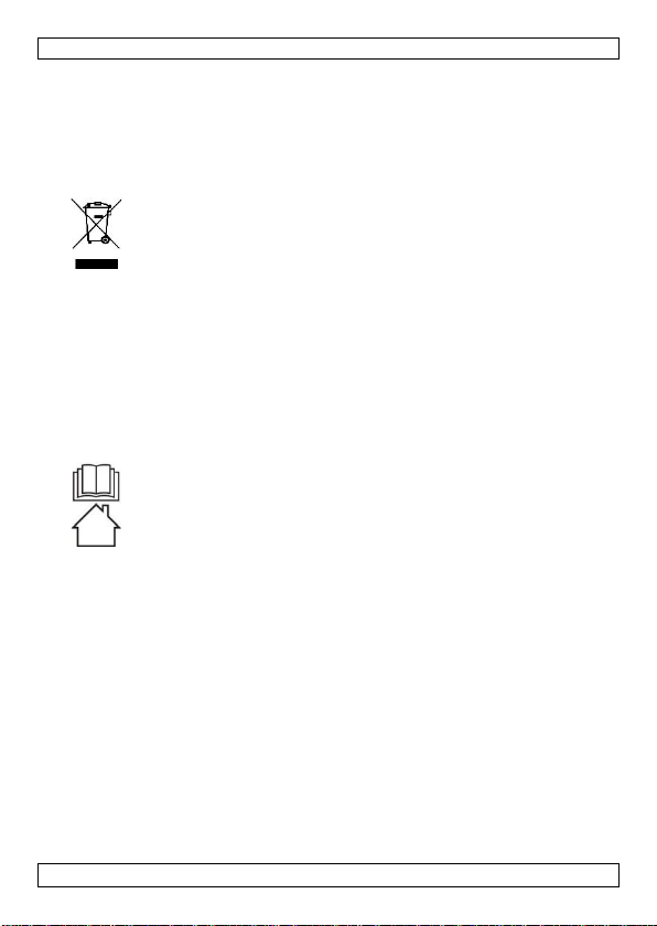
Belangrijke milieu-informatie betreffende dit product
Dit symbool op het toestel of de verpakking geeft aan dat, als
het na zijn levenscyclus wordt weggeworpen, dit toestel schade
kan toebrengen aan het milieu. Gooi dit toestel (en eventuele
batterijen) niet bij het gewone huishoudelijke afval; het moet bij
een gespecialiseerd bedrijf terechtkomen voor recyclage. U moet
dit toestel naar uw verdeler of naar een lokaal recyclagepunt
brengen. Respecteer de plaatselijke milieuwetgeving.
Hebt u vragen, contacteer dan de plaatselijke autoriteiten
betreffende de verwijdering.
Bedankt voor uw aankoop! Lees deze handleiding grondig door
voor u het toestel in gebruik neemt. Werd het toestel beschadigd
tijdens het transport, installeer het dan niet en raadpleeg uw
dealer.
2. Veiligheidsvoorschriften
Lees en begrijp deze handleiding en de veiligheidsinstructies vóór
ingebruikname.
Uitsluitend voor gebruik binnenshuis.
•Dit toestel is geschikt voor gebruik door kinderen vanaf
8 jaar, door personen met fysieke, zintuiglijke of
verstandelijke beperkingen, of door personen met gebrek
aan ervaring en kennis, op voorwaarde dat dit onder
toezicht gebeurt van een persoon die verantwoordelijk is
voor hun veiligheid of hun aanwijzingen heeft gegeven, hoe
zij het toestel moeten gebruiken en zich bewust zijn van de
risico's die het gebruik van het toestel met zich meebrengt.
Kinderen mogen niet met het toestel spelen. De reiniging en
het onderhoud van het toestel mogen niet worden
uitgevoerd door kinderen, tenzij ze onder toezicht staan.
•Raadpleeg de Velleman® service- en kwaliteitsgarantie
achteraan deze handleiding.
•Om veiligheidsredenen mag u geen wijzigingen aanbrengen.
Schade door wijzigingen die de gebruiker heeft aangebracht
aan het toestel valt niet onder de garantie.

HAA52N
V. 03 –08/06/2020 9 ©Velleman nv
•Gebruik het toestel enkel waarvoor het gemaakt is. De
garantie vervalt automatisch bij ongeoorloofd gebruik.
•De garantie geldt niet voor schade door het negeren van
bepaalde richtlijnen in deze handleiding en uw dealer zal de
verantwoordelijkheid afwijzen voor defecten of problemen
die hier rechtstreeks verband mee houden.
•Noch Velleman nv noch zijn verdelers kunnen aansprakelijk
gesteld worden voor schade (buitengewoon, incidenteel of
onrechtstreeks) –van welke aard dan ook (financieel,
fysisch…) voortvloeiend uit het bezit, gebruik of falen van dit
product.
•Bewaar deze handleiding voor verdere raadpleging.
3. Detectiebereik
Raadpleeg de afbeeldingen op pagina 2 van deze handleiding.
4. Omschrijving printplaat
Raadpleeg de afbeeldingen op pagina 2 van deze handleiding.
1
bevestigingschroef
5
test- en alarmled
2
alarmuitgangjumper
6
pyro-elektrische sensor
(niet aanraken!)
3
impulsjumper
7
aansluitblok
4
aan-uitjumper voor
de led
8
antisabotageschakelaar
4.1 Omschrijving aansluitingsterminal
ALARM
Dit is de alarmuitgang van de detector en kan als normaal
gesloten (NC) of normaal open (NO) ingesteld worden via de
alarmjumper om aan de vereisten van de te bewaken zone te
voldoen.
DC12V
Sluit de positieve (+) terminal aan een DC-voedingsbron van
8~16 V aan, doorgaans afkomstig van een bedieningspaneel. Sluit
de negatieve (-) terminal aan de gemeenschappelijke aarding van
het bedieningspaneel.
TAMP
NC
Wenst u een antivandalismeschakelaar, sluit deze terminals dan
aan een normaal gesloten 24-uur beveiligingszone op het
bedieningspaneel. Dit contact is normaal gesloten wanneer het
deksel op de detector gemonteerd is. Bij het openen van de
detector zal dit contact openen en een alarmsignaal naar het
bedieningspaneel sturen.

HAA52N
V. 03 –08/06/2020 10 ©Velleman nv
4.2 Jumperinstellingen
LED
AAN
Led is ingeschakeld
ON = alarm ingeschakeld.
FLASH = inschakelprocedure.
OFF
Led is uitgeschakeld. Heeft geen invloed op de prestaties
van de detector.
MODE
S
Standaard signaalverwerking met wisselende polariteit,
geschikt voor een stabiele omgeving.
P
Dubbele signaalverwerking met wisselende polariteit,
geschikt voor een omgeving met wisselende
eigenschappen.
ALARM
NC
Dit uitgangscontact is normaal gesloten. Het relais trekt
doorgaans aan.
NO
Dit uitgangscontact is normaal open. Het relais valt
doorgaans af.
5. Gebruik
5.1 Montageplaats
•De detector kan op een effen oppervlak of in een hoek
gemonteerd worden. Plaats het toestel echter altijd op een
stevige ondergrond.
•De detector moet binnenshuis gemonteerd worden, in een
ruimte zonder openingen en die niet constant aan invloeden
van de buitenlucht onderhevig zijn.
•Kies de locatie voor de montage van de detector zorgvuldig,
zodat elke beweging van een eventuele inbreker binnen het
detectiebereik valt.
•Monteer de detector niet op plaatsen waar hij blootgesteld
wordt aan warme- of koudeluchtstromen.
•Zorg ervoor dat de detector niet naar het buizenstel van
verwarming- of airconditioningsystemen is gericht, noch
naar metalen buitenmuren, buitenramen of gordijnen die
buitenramen verbergen, de verdamper van een koelkast of
diepvrieskast, of om het even welk ander oppervlak dat aan
temperatuurschommelingen onderhevig is.
•Probeer er eveneens op toe te zien dat men geen grote
voorwerpen vóór de detector plaatst; deze kunnen immers
een belangrijke invloed hebben op de bewakingsruimte, of
althans op het volume ervan.
•Kies een montageplaats die het mogelijk maakt de detector
in een hoek van 45° te plaatsen ten opzichte van de
overtreder. Monteer de detector op een hoogte van 2~3 m.

HAA52N
V. 03 –08/06/2020 11 ©Velleman nv
5.2 Verwijderen van het deksel
Maak de schroef onderaan de detector los en verwijder het deksel.
5.3 Verwijderen van de printplaat
Voor de montage moet u de printplaat verwijderen. Maak de
bevestigingsschroef los en verwijder de printplaat voorzichtig uit
de detector.
5.4 Monteren van het achterste deksel
De detector kan op een effen oppervlak, in een hoek of op de
beugel gemonteerd worden.
•Perforeer de kabelopening en de montageopeningen
achteraan de detector volgens de gekozen montageoptie (op
een effen oppervlak, in een hoek of op de beugel).
•Bevestig de detector of montagebeugel met de schroeven
(bevestig daarna de detector op de montagebeugel).
Raadpleeg de afbeeldingen op pagina 2 van deze handleiding.
1
afdekking
(achterkant)
3
montagebeugel
2
bevestigingsschroef
5.5 Bekabeling en afwerking
•Bevestig de printplaat in de detector.
•Bekabel het aansluitblok.
•Plaats het deksel en bevestig met de schroef. Zorg dat u de
anti-vandalismeschakelaar hoort klikken. Richt de detector.
6. Test
•U kunt de detector testen na de opwarmprocedure - de
alarmled knippert tijdens de procedure.
•Wandel door de bewaakte zone aan een snelheid van een
stap per seconde. Houd de led in het oog.
•De led licht onmiddellijk op indien de standaard
signaalverwerking met wisselende polariteit is ingesteld.
•Werkt de detector echter met de pulsteller, of de dubbele
signaalverwerking met wisselende polariteit, dan dient u
enkele stappen te nemen vooraleer het alarm afgaat.

HAA52N
V. 03 –08/06/2020 12 ©Velleman nv
7. Technische specificaties
stroomverbruik..............................................15 mA @ 12 VDC
werkspanning................................ 8-16 VDC, 12 VDC nominaal
detectiemethode........................... PIR met wisselende polariteit
inschakeltijd................................... 2 min. met knipperende led
alarmperiode...................................................... 2-3 seconden
alarmuitgang............................................... NO- of NC-contact
.................................................met inlineweerstand van 10 Ω
testled................................. alarmaanduiding, in-/uitschakeling
impulstelling ................normale respons of 2 pulsen binnen 10 s
antisabotageschakelaar .......................................... NC-contact
.................................................met inlineweerstand van 10 Ω
werktemperatuur..........................................-10 °C tot +55 °C
vochtigheid ........................................ 95 % niet-condenserend
afmetingen ................................................. 105 x 60 x 42 mm
gewicht ..........................................................................82 g
Gebruik dit toestel enkel met originele accessoires.
Velleman nv is niet aansprakelijk voor schade of
kwetsuren bij (verkeerd) gebruik van dit toestel. Voor
meer informatie over dit product en de laatste versie van
deze handleiding, zie www.velleman.eu. De informatie in
deze handleiding kan te allen tijde worden gewijzigd
zonder voorafgaande kennisgeving.
© AUTEURSRECHT
Velleman nv heeft het auteursrecht voor deze handleiding.
Alle wereldwijde rechten voorbehouden. Het is niet
toegestaan om deze handleiding of gedeelten ervan over te
nemen, te kopiëren, te vertalen, te bewerken en op te slaan op
een elektronisch medium zonder voorafgaande schriftelijke
toestemming van de rechthebbende.

HAA52N
V. 03 –08/06/2020 13 ©Velleman nv
MODE D'EMPLOI
1. Introduction
Aux résidents de l'Union européenne
Informations environnementales importantes concernant
ce produit
Ce symbole sur l'appareil ou l'emballage indique que l’élimination
d’un appareil en fin de vie peut polluer l'environnement. Ne pas
jeter un appareil électrique ou électronique (et des piles
éventuelles) parmi les déchets municipaux non-sujets au tri
sélectif ; une déchetterie traitera l’appareil en question.
Renvoyer l'appareil à votre fournisseur ou à un service de
recyclage local. Respecter la réglementation locale relative à la
protection de l’environnement.
En cas de questions, contacter les autorités locales pour
élimination.
Nous vous remercions de votre achat ! Lire attentivement le
présent mode d'emploi avant la mise en service de l’appareil. Si
l'appareil a été endommagé pendant le transport, ne pas
l’installer et consulter votre revendeur.
2. Consignes de sécurité
Lire et comprendre ce mode d'emploi et toutes les consignes de
sécurité avant d'utiliser l'appareil.
Utiliser cet appareil uniquement à l'intérieur.
•Cet appareil peut être utilisé par des enfants âgés de 8 ans
et plus et des personnes manquant d’expérience et de
connaissances ou dont les capacités physiques, sensorielles
ou mentales sont réduites, si elles ont été formées et
encadrées quant à l'utilisation de l'appareil d'une manière
sûre et connaissent les risques encourus. Ne pas laisser les
enfants jouer avec l'appareil. Le nettoyage et l'entretien ne
doivent pas être effectués par des enfants sans surveillance.
•Se référer à la garantie de service et de qualité Velleman®en
fin de ce mode d'emploi.
•Toute modification est interdite pour des raisons de sécurité.
Les dommages occasionnés par des modifications par le
client ne tombent pas sous la garantie.

HAA52N
V. 03 –08/06/2020 14 ©Velleman nv
•N’utiliser l'appareil qu’à sa fonction prévue. Un usage
impropre annule d'office la garantie.
•La garantie ne se s’applique pas aux dommages survenus en
négligeant certaines directives de ce mode d'emploi et votre
revendeur déclinera toute responsabilité pour les problèmes
et les défauts qui en résultent.
•Ni Velleman SA ni ses distributeurs ne peuvent être tenus
responsables des dommages exceptionnels, imprévus ou
indirects, quelles que soient la nature (financière,
corporelle, etc.), causés par la possession, l’utilisation ou le
dysfonctionnement de ce produit.
•Garder ce mode d'emploi pour toute référence ultérieure.
3. Surface de détection
Se référer aux illustrations en page 2 de ce mode d'emploi.
4. Description du CI
Se référer aux illustrations en page 2 de ce mode d'emploi.
1
vis de fixation du
CI
5
LED
2
cavalier de sortie
d’alarme
6
capteur
pyroélectrique (ne
pas toucher!)
3
cavalier du mode
d’impulsion
7
bloc de connexion
4
cavalier de
(dés)activation de
la LED
8
interrupteur anti-
sabotage
4.1 Description du bloc de connexion
ALARM
Contact du relais de sortie d’alarme. Ce contact est normalement
fermé (NF) ou ouvert (NO) et peut être paramétré depuis le
cavalier de sortie d’alarme afin de répondre aux conditions de la
zone à protéger.
DC12V
Raccorder la borne positive (+) à une source d’alimentation CC
8 V ~ 16 V, généralement provenant du panneau de commande.
Raccorder la borne négative (-) à la masse commune du panneau
de commande.

HAA52N
V. 03 –08/06/2020 15 ©Velleman nv
TAMP NC
Si un contact anti-sabotage est souhaité, raccorder ces bornes à
une zone de protection 24 heures dans le panneau de
commande. Ce contact est un contact NF lorsque le boîtier du
détecteur est fermé. Une ouverture non souhaitée du boîtier
ouvrira le contact et enverra un signal d’alarme vers le panneau
de commande.
4.2 Paramétrage des cavaliers
LED
ON
Activation de la LED
Allumée = alarme amorcée.
Clignotement = processus de chauffe.
OFF
Désactivation de la LED. N’affecte pas les performances
de détection.
MODE
S
Traitement des signaux à polarité alternée standard
pour les environnements stables.
P
Double traitement des signaux à polarité alternée pour
les environnements instables.
ALARM
NC
Contact du relais de sortie d’alarme NF. Le relais de
sortie est généralement activé.
NO
Contact du relais de sortie d’alarme NO. Le relais de
sortie est généralement désactivé.
5. Emploi
5.1 Lieu de montage
•Le détecteur peut se monter en surface, en coin ou sur
support. Installer l’unité sur une surface résistante.
•Monter le détecteur à l’intérieur dans un lieu où les
ouvertures ne sont pas constamment exposées à
l’environnement extérieur.
•Choisir le point de fixation en fonction des mouvements
escomptés de l’intrus, de sorte que ce dernier traverse le
faisceau du détecteur.
•Ne pas placer le détecteur là où l’unité sera directement
exposée à des courants d’air chaud ou froid.
•Éviter de diriger le faisceau du détecteur sur des
canalisations de climatiseur ou des conduits de chauffage,
des parois métalliques externes, des fenêtres extérieures
pourvues ou non de tentures tirées, des calandres de
réfrigérateurs ou congélateurs ou toute autre surface qui
peut changer de température rapidement.
•Éviter de placer des objets encombrants devant le détecteur
car ils modifieraient considérablement la zone ou le volume
de protection.

HAA52N
V. 03 –08/06/2020 16 ©Velleman nv
•Sélectionner le point de fixation de manière à ce que l’angle
de visée soit de 45° par rapport à l’intrus. Installer le
détecteur à une hauteur de 2~3 m.
5.2 Ouverture du détecteur
Desserrer la vis au bas du détecteur et retirer la face frontale.
5.3 Démontage du CI
Le montage implique le démontage du CI. Desserrer la vis de
fixation et retirer le CI avec précaution.
5.4 Montage du détecteur
Le détecteur peut se monter en surface, en coin ou sur le support
inclus.
•Perforer la face arrière de manière à créer une ouverture
pour le câblage et des ouvertures de fixation (selon le mode
de fixation : en surface, en coin ou sur support).
•Fixer la face arrière ou le support et ensuite le détecteur à
l’aide des vis.
Se référer aux illustrations en page 2 de ce mode d'emploi.
1
couvercle arrière
3
support de
montage
2
vis de fixation
5.5 Câblage et finition
•Installer le CI dans le détecteur.
•Câble dûment le bloc de connexion.
•Placer la face avant et refermer le détecteur avec la vis.
Veiller à ce que le contact anti-sabotage s’enfonce avec un
déclic. Aligner le détecteur.
6. Test de communication
•L’essai peut s’effectuer après le processus de chauffe - la
LED clignote tout au long de ce processus.
•Marcher dans la zone de détection au rythme d’un pas par
seconde et observer la LED.
•L’alarme s’enclenche lorsque le détecteur est en mode de
traitement des signaux à polarité alternée standard.

HAA52N
V. 03 –08/06/2020 17 ©Velleman nv
•Faire deux à trois pas lorsque le détecteur est en mode de
comptage d’impulsion.
7. Spécifications techniques
consommation de courant...............................15 mA @ 12 VCC
tension d'opération ......................... 8~16 VCC, 12 VCC nominal
méthode de détection.................. capteur PIR à polarité alternée
délai d’armement.......................2 minutes avec LED clignotante
période d’alarme................................................. 2-3 secondes
sortie d'alarme ........contact NO ou NF à résistance en ligne 10 Ω
LED d’essai ........... indication d’alarme, armement/désarmement
comptage d’impulsion... réponse normale ou 2 impulsions en 10 s
interrupteur anti-sabotage . contact NF à résistance en ligne 10 Ω
température de service....................................-10 °C à +55 °C
humidité................................................... 95 % non condensé
dimensions ................................................. 105 x 60 x 42 mm
poids..............................................................................82 g
N'employer cet appareil qu’avec des accessoires d’origine.
Velleman SA ne peut, dans la mesure conforme au droit
applicable être tenue responsable des dommages ou
lésions (directs ou indirects) pouvant résulter de
l’utilisation de cet appareil. Pour plus d'informations
concernant cet article et la dernière version de ce mode
d'emploi, consulter notre site www.velleman.eu. Les
spécifications et le continu de ce mode d'emploi peuvent
être modifiés sans notification préalable.
© DROITS D’AUTEUR
Velleman SA est l’ayant droit des droits d’auteur de ce
mode d'emploi. Tous droits mondiaux réservés. Toute
reproduction, traduction, copie ou diffusion, intégrale ou
partielle, du contenu de ce mode d'emploi par quelque procédé
ou sur tout support électronique que ce soit est interdite sans
l’accord préalable écrit de l’ayant droit.

HAA52N
V. 03 –08/06/2020 18 ©Velleman nv
MANUAL DEL USUARIO
1. Introducción
A los ciudadanos de la Unión Europea
Importantes informaciones sobre el medio ambiente
concerniente a este producto
Este símbolo en este aparato o el embalaje indica que, si tira las
muestras inservibles, podrían dañar el medio ambiente. No tire
este aparato (ni las pilas, si las hubiera) en la basura doméstica;
debe ir a una empresa especializada en reciclaje. Devuelva este
aparato a su distribuidor o a la unidad de reciclaje local. Respete
las leyes locales en relación con el medio ambiente.
Si tiene dudas, contacte con las autoridades locales para
residuos.
¡Gracias por elegir EtiamPro! Lea atentamente las instrucciones del
manual antes de usar el aparato. Si ha sufrido algún daño en el
transporte no lo instale y póngase en contacto con su distribuidor.
2. Instrucciones de seguridad
Lea y comprenda este manual y todas las instrucciones de
seguridad antes de usar el aparato.
Utilice el aparato sólo en interiores.
•Este aparato no es apto para niños menores de 8 años ni
para personas con capacidades físicas, sensoriales o
mentales reducidas ni para personas con una falta de
experiencia y conocimientos del producto, salvo si están
bajo la vigilancia de una persona que pueda garantizar la
seguridad. Asegúrese de que los niños no jueguen con este
dispositivo. Nunca deje que los niños limpien o manipulen el
aparato sin supervisión.
•Véase la Garantía de servicio y calidad Velleman®al final de
este manual del usuario.
•Por razones de seguridad, las modificaciones no autorizadas del
aparato están prohibidas. Los daños causados por modificaciones
no autorizadas, no están cubiertos por la garantía.
•Utilice sólo el aparato para las aplicaciones descritas en este
manual. Su uso incorrecto anula la garantía completamente.
•Los daños causados por descuido de las instrucciones de
seguridad de este manual invalidarán su garantía y su

HAA52N
V. 03 –08/06/2020 19 ©Velleman nv
distribuidor no será responsable de ningún daño u otros
problemas resultantes.
•Ni Velleman nv ni sus distribuidores serán responsables de
los daños extraordinarios, ocasionales o indirectos, sea cual
sea la índole (financiera, física, etc.), causados por la
posesión, el uso o el fallo de este producto.
•Guarde este manual del usuario para cuando necesite
consultarlo.
3. Rango de detección
Véase la figura en la página 2 de este manual del usuario.
4. Descripción - Circuito Impreso
Véase las figuras en la página 2 de este manual del usuario.
1
tornillo de fijación
5
indicador
test/alarma
2
jumper de la salida
de alarma
6
sensor piroeléctrico
(¡no tocar!)
3
jumper del modo
de impulsos
7
bloque de conexión
4
jumper LED de
encendido/apagado
8
interruptor de
manipulación
(tamper)
4.1 Descripción - Bloque de conexión
ALARM
Contacto de relé de salida de alarma. Este contacto está
normalmente cerrado (NC) o abierto (NA) y se puede regular con
el jumper del salida de alarma para cumplir con los requisitos de
la zona que quiere proteger.
DC12V
Conecte el borne positivo (+) a una fuente de alimentación DC
8 V ~ 16 V, que viene generalmente del panel de control.
Conecte el borne negativo (-) a la masa común del panel de
control.
TAMP NC
Si fuera necesario un interruptor de manipulación (tamper),
conecte estos bornes a una zona de protección 24 horas del
panel de control. Este interruptor de manipulación (tamper) es
un contacto NC si la carcasa del detector está cerrada. Cuando se
abre la carcasa se abrirá el contacto y se enviará una señal de
alarma al panel de control.

HAA52N
V. 03 –08/06/2020 20 ©Velleman nv
4.2 Configuración de los cables de puente
LED
ON
El LED está activado
ON = la alarma está activada.
FLASH = proceso de activación
OFF
El LED está desactivado No afectará la detección.
MODE
OFF
El LED está desactivado No afectará la detección.
S
Procesamiento de señales con polaridad alternante
estándar. Para ambientes estables.
P
Doble procesamiento de señales con polaridad
alternante estándar. Para ambientes inestables.
ALARM
NC
El contacto de relé de salida de alarma está cerrado
(NC). El relé de salida está normalmente activado.
NO
El contacto de relé de salida de alarma está abierto
(NA). El relé de salida está normalmente desactivado.
5. Funcionamiento
5.1 Lugar de montaje
•Es posible instalar el detector en una superficie, o una
esquina o puede utilizar el soporte incluido. Instale siempre
el aparato en una superficie estable.
•Monte el detector en interiores en un lugar que no esté
expuesto a las influencias de los elementos.
•Asegúrese de que cualquier movimiento esté detectado por
el aparato.
•No exponga el aparato a corrientes de aire calientes o frías.
•No dirija el aparato hacia aparatos de calefacción, rejillas de
ventilación, ventanas exteriores, rejillas de congeladores o
neveras ni hacia cualquier superficie sujeta a variaciones de
temperatura repentinas y violentas.
•No coloque objetos voluminosos delante del detector porque
disminuirán la zona de detección.
•Seleccione un lugar de montaje que permita utilizar el
detector bajo un ángulo de 45° (ángulo óptimo) con
respecto al lugar donde el intruso probablemente entrara en
el campo de vigilancia. Instale el detector a una altura de 2
~ 3 m.
Table of contents
Languages:
Other EtiamPro Security Sensor manuals
Popular Security Sensor manuals by other brands

UTC Fire and Security
UTC Fire and Security interlogix DI601AM Installation sheet

jablotron
jablotron JA-80PB quick start guide

Bircher Reglomat
Bircher Reglomat RBM 2 Translation of the original operation instruction

Lince
Lince 1597ZENITHDT Programming and operating manual

STEINEL
STEINEL Professional Series instructions

LEGRAND
LEGRAND CP Electronics EBDHS-KNX installation guide