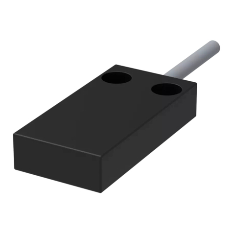
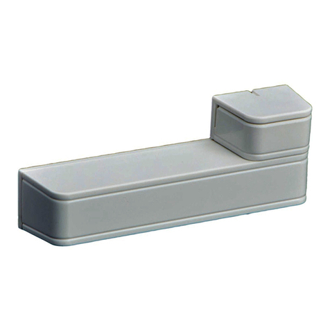
elobau eloProtect E 165ESK Series Quick guide

Art.-Nr./Art. No./Réf./N° art/N° art.: 9010017B01M Version: 1.0 Date: 25.05.2016 1/15
165ESK...
Safety sensor series 165ESK...
Translation of the original operating instructions
Table of contents
1About these operating instructions .......................................................1
1.1 Validity .............................................................................................1
1.2 Number key safety sensor 165ESK ................................................1
1.3 Number key actuator .......................................................................1
2Intended use.........................................................................................1
3Approvals..............................................................................................1
4Safety information.................................................................................2
5Warning against misuse .......................................................................2
6Disclaimer.............................................................................................2
7Function................................................................................................2
7.1 Coding variants................................................................................2
7.2 Safety outputs..................................................................................2
7.3 Safety inputs....................................................................................2
7.4 EDM input........................................................................................3
7.5 Diagnostic output.............................................................................3
7.6 LED displays, flash codes and clocking diagnostic output ..............3
7.7 Boundary area monitoring ...............................................................3
8Technical specifications........................................................................3
9Assembly ..............................................................................................3
10 Adjustment............................................................................................4
11 Electrical connection.............................................................................4
11.1 Series connection ............................................................................4
11.2 Information about power supply ......................................................4
11.3 Note for use in safety control systems.............................................4
12 Commissioning .....................................................................................4
12.1 Teach-in variant "individual" ............................................................4
13 Maintenance .........................................................................................4
13.1 Accessories .....................................................................................5
14 Troubleshooting....................................................................................5
GB
15 Dismantling...........................................................................................5
16 Disposal................................................................................................5
17 Information about production date........................................................5
Declaration of conformity ..............................................................................14
1 About these operating instructions
1.1 Validity
Variants of the following basic types are described:
- 165ESK00
Data sheets can be requested additionally from elobau for customer-specific
sensors. The information in the data sheet for customer-specific types, if they
differ from the operating instructions.
The operating instructions are to be made available to the person who is in-
stalling the safety sensor.
The operating instructions are to be kept in a legible condition and accessible
at all times.
Definition of symbols:
Warning
Failure to comply can result in malfunctions or interference.
Failure to comply can result in injury and/or damage to the
machine.
Information
Identifies available accessories and useful additional informa-
tion.
1.2 Number key safety sensor 165ESK ...
165ESK00 . . .
Description EDM input
1 = EDM input automatic
2 = EDM input monitored (start button)
Coding variant
1 = coded
2 = unique
3 = individual
Connection option
J = Connector M12x1; 8-pin; pigtail 150 mm
K = Cable
1.3 Number key actuator
2 Intended use
The safety sensors 165ESK ... and actuator 165EBK ... may be used
exclusively for monitoring movable, separating safety guards.
This can be done in conjunction with a elobau safety relay or comparable safety
controller. The sensor can also be used without additional safety relay/controller,
due to the integrated evaluation logic in the sensor as well as EDM input.
The overall control concept in which the security sensor is incorporated is to
be validated, for example, according to EN ISO 13849-2.
165EBK001
coded
3 Approvals
[PROXIMITY SWITCH]
E470178
(tested in accordance with
ECOLAB standard)
Tested chemical resistance to the
following cleaning detergents:
- Distilled water
- P3-topax 66
- P3-topactive 200
- P3-topax 52
- P3-topax 990

Art.-Nr./Art. No./Réf./N° art/N° art.: 9010017B01M Version 1.0 Date: 25.05.2016 2/15
165ESK...
4 Safety information
5 Warning against misuse
6 Disclaimer
No liability can be accepted for damage or outages resulting from non-compli-
ance with this instruction manual. For damage resulting from the use of spare
parts or accessories unapproved by the manufacturer, any further liability of
the manufacturer is excluded.
Any unauthorized repairs, modifications and additions are not permitted for
safety reasons and the manufacturer is also not liable for any resulting damage.
- Make sure that the safety sensors are mounted only by specially
trained, authorized, qualified personnel and put into service
safely.
- Only install and commission the device if you have read and
understood the operating instructions and are familiar with the
applicable regulations on occupational safety and accident
prevention.
- The safety sensor may only be operated exclusively by the
actuator which is properly mounted on the guard. Actuation
when not mounted on the guard is prohibited.
- Operate the safety sensors only if they are in undamaged
condition.
- Make sure that the safety sensors are used exclusively to
protect against hazards.
- Make sure that all applicable safety requirements for the respec-
tive machine are complied with.
- Make sure that all applicable laws and regulations are complied
with.
- Residual risks are not known when the instructions in this man-
ual are adhered to.
- Inexpert or improper use or tampering in combination with the
use of safety sensors can lead to hazards for personnel or
damage to machine or system parts.
Also observe the relevant notes relating to EN ISO 14119.
- Make sure that no external component causes current or
voltage peaks which are higher than the specified electrical data
of the safety relay. Current or voltage peaks are produced for
example by capacitive or inductive loads.
- Exceeding the electrical data of the safety sensor (e.g. in case
of faulty wiring or shorts) can damage it irreparably.
- Operation of the safety sensor is only allowed with the
appropriate actuator and with the approved control options (see
Technical specifications).
7 Function
Coded, electronic safety sensor, which is operated by a non-contact coded
actuator.
Safety sensors are suitable for the following elobau safety relays:
eloFlex 470EFR...
eloFlex 471EFR...
eloProg 485EPB
485EPE08A02
485EPE08
4854EPE12
485EPE16
7.1 Coding variants
The various versions of the safety sensors arise from the different encodings
designated as type keys under point 1.2. Depending on the variant, a corre-
sponding manipulation protection is achieved.
Coded
The safety sensor accepts any eloProtectE actuator of type 165EBK001.
Type 4; low level coding level according to EN ISO 14119
Individual
The safety sensor accepts one eloProtectE actuator of type 165EBK001. This
actuator is configured individually to the safety sensor. A non-matching actu-
ator in the sensor range will result in an error.
The process for teaching-in a new actuator can be carried out unlimited times
and is descried in detail under "Commissioning" on page 4.
Type 4; high level coding level according to EN ISO 14119.
Unique
The safety sensor only accepts the eloProtectE actuator supplied. The pair,
consisting of sensor and actuator cannot be separated. If a component should
be lost and is no longer functional, both components must be replaced.
Type 4; high level coding level according to EN ISO 14119.
7.2 Safety outputs
The safety sensor has 2 short-circuit proof PNP safety outputs (OSSD), which
have a max. load of 400 mA per channel.
The safety outputs switch on under the following conditions:
- the correct actuator is detected in the operating range (safety guard closed)
- a high signal is present at both safety inputs
- the EDM input is set correctly
- no error is detected
The safety outputs switch off under the following conditions:
- There is no actuator or the wrong actuator in the detection zone
- Signal is low at one of the two inputs
- An error is detected
The two safety outputs can be connected under the following conditions to the
inputs of a safety controller:
- the input must be appropriate (OSSD signals) for clocked safety signals; the
controller must tolerate test pulses on the inputs (see Technical specifications
on page 7). Please refer to the instructions of the controller manufacturer.
-
Wiring examples can be found on page 12.
7.3 Safety inputs
The safety sensor has 2 safety inputs.
-Connect the safety inputs of +24 V DC for single use of the sensor
When using the sensor in a series connection, the safety inputs of the first
sensor can be connected to +24 V DC. The safety inputs of the following
sensors are connected to the safety outputs of the previous sensor. Please
also refer to point 11.1 "Series connection" on page 8.
- Pulses with a duration of max. 900 μs are tolerated on the safety inputs.

Art.-Nr./Art. No./Réf./N° art/N° art.: 9010017B01M Version: 1.0 Date: 25.05.2016 3/15
165ESK...
Wiring examples can be found on page 12.
7.4 EDM input
The EDM input can be configured as "automatic" or "monitored" (see number
key).
If the EDM input is not required, the "automatic" variant must be selected and
connected to +24 V DC.
EDM input: automatic
For contactor monitoring, the open contactors must be connected to the EDM
input.
For series connection of multiple sensors all EDM inputs must be connected
to +24 V DC. The monitor for the contactors must be connected to the last sen-
sor of the chain.
Wiring examples can be found on page 12.
EDM input: monitors (start button)
Connect the EDM input to an external start button on your machine control.
The EDM input is only then recognized as set properly if after pressing the
sensor and after setting the safety inputs at least one valid start pulse is
detected.
The valid start pulse is detected when after a rising edge, a falling edge within
the allowable start pulse duration between 30 ms and 5 s is detected.
Wiring examples can be found on page 12.
7.5 Diagnostic output
The diagnostic output is positive switching, short-circuit protected and trans-
mits the various sensor states with different signals, for example, to a PLC.
The pulsed signals correspond to the timing of the yellow LED.
The various symbols are described in more detail under point 7.6.
7.6 LED displays, flash codes and clocking diagnostic output
Sensor non-actuated
LED green off
LED red off
LED yellow on
Diagnostic output 0 V
Safety outputs 0 V
Note Voltage is applied
Actuator in the detection area (sensor activated), all inputs correctly set
LED green on
LED red off
LED yellow off
Diagnostic output 24 V DC
Safety outputs 24 V
Note Actuator in the detection area
Actuator in the detection area (sensor actuated),
safety inputs not set (low level)
LED green flashes1)
LED red off
LED yellow off
Diagnostic output 24 V DC
Safety outputs 0 V
Note Set safety inputs
Actuator in the detection area (sensor actuated),
safety inputs set (high level), waits for start pulse
LED green rapid flashes2)
LED red off
LED yellow off
Diagnostic output 24 V DC
Safety outputs 0 V
Note Press Start button
Actuator at the reception limit
LED green off
LED red off
LED yellow flashes1)
Diagnostic output 24 V DC clocked
Safety outputs Previous state
Note Readjust sensor
Teach-in process
LED green off
LED red off
LED yellow rapid flashes2)
Diagnostic output 24 V DC clocked
Safety outputs 0 V
Note Disconnect voltage to complete teach-in
1) Flashing: The pulse intervals of the LED ratio is 1:1.
2) Rapid flashing: The pulse intervals of the LED ratio is 1: 4.
Fault condition
LED green off
LED red flashes1)
LED yellow off
Diagnostic output 0 V
Safety outputs 0 V
Note See "Troubleshooting" on page 9.
7.7 Boundary area monitoring
If the actuator is in the boundary area of the switching distances with corre-
sponding offset values of the sensor, it is transmitted to a PLC or indicated by
the LED (see point 7.6).
8 Technical specifications
See Technical specifications from page 24.
9 Assembly
- Safety sensor and actuator
do not use as a stopper
external fields can affect switching distances
- Installation of the safety sensor and the associated actuator is allowed only
when de-energized.
-
-
Make sure that the markings on the sensor and actuator face each other
congruently.
The mounting position is arbitrary. However, security sensor and actuator
must be mounted parallel and opposite each other.
- Note the specified installation tolerances and the approved control options.
The specified operating distance around the free zone must be maintained
(free of electrically and magnetically conductive materials).
Matching spacer plates for mounting on metal parts are available
under the order no. 350005 (8 mm) and 350008 (10 mm) from elobau.

Art.-Nr./Art. No./Réf./N° art/N° art.: 9010017B01M Version: 1.0 Date: 25.05.2016 4/15
165ESK...
- The mounting distance between two systems of the safety sensor and
actuator must be min. 15 cm.
- Attach safety sensor and actuator to the protective device so that they
cannot be removed.
- Use only M4 screws with flat head (e.g. M4 cheese head screws ISO 4762)
for installation of the safety sensor and actuator. Tightening torque max.
0.7 Nm. Use non-ferromagnetic material (e.g. brass) screws.
- The safety sensor must be mounted on flat surfaces.
- The connecting cable of the safety sensor must be protected against
mechanical damage.
- Consider the requirements of EN ISO 14119 during installation.
- The stated operating distances (see Technical specifications from page 24)
are only valid for mounting on non-metallic material if the safety sensor and
actuator are mounted in parallel opposite each other. Other arrangements
may lead to different switching states.
11 Electrical connection
- Connect the safety sensor according to the specified wire colors and pin
assignment (see "Circuit diagram and pin assignment" on page 28).
- Make sure that the required minimum input voltage of the downstream safety
relay is not undershot. Observe the voltage drop at the safety sensor and the
connecting cable.
11.1 Series connection
The safety sensors enable a series connection with up to 30 sensors while
achieving up to PLe with correct wiring.
For a series connection it must be noted that the time delay accumulates for
each additional sensor. The relevant technical specifications can be found in
the table from page 24.
Configuration EDM input see point 7.4
Wiring examples can be found on page 12. Additional wiring examples, for
example, with T-distributors, can be downloaded from our website http://
www.elobau.com/Machine_safety.
The maximum number of safety sensors, as well as the total length of the sen-
sor chain is load-dependent.
Increasing line length and increasing current load (load + sensors) in the se-
ries connection increases the voltage drop within the system. If the voltage
falls below the permissible value of 21.6 V, a new feed supply must be added.
The elobau T-distributor 350ATD7K can be used for this purpose.
11.2 Information about power supply
- The sensor must be powered directly or indirectly with a SELV/PELV power
supply.
- For use and applications as per the requirements1), the power supply must
be classified "for use in class 2 circuits".
1) Notice regarding the scope of the UL approval: The devices have been
tested in accordance with the requirements of UL508 and CSA/C22.2 no. 14
(protection against electric shock and fire).
11.3 Note for use in safety control systems
- Do not use controllers with test pulses or turn off the test pulses in your control
system. The device generates its own test pulses to the safety outputs. A
downstream control system must be able to tolerate these test pulses, which
may have a length up to 300 s. Depending on the inertia of the connected
device (control, relay, etc.), this can lead to short switching processes.
- The inputs of a connected evaluation unit must be positive-switching, as the
two outputs on the safety switch in the ON state deliver a level of +24 V DC.
12 Commissioning
During commissioning, you must make sure of the following points:
- safety sensor and actuator mounted in the correct position and firmly
- integrity of the supply line
We recommend using the screw covers included to secure the
mounting screws against easy disassembly.
The electrical connections must be made without voltage applied
and may be performed by authorized personnel only.
Matching cable sets (type no.: K18G00.K) and an installation
wrench (type no.: MS03) are available directly from Elobau for safe-
ty sensors with connectors. We also offer options for easy wiring in
series connection. T-distributor (Item no.: 350A...K..) and connect-
ing cable (Item no.: K5.G00.K). (For more information see point
13.1 "Accessories" on page 9.)
- Both safety outputs must always be evaluated to ensure safety.
- Since the diagnostic output is not a safety output, it may not be
used for safety-relevant information and monitoring functions.
- Also consider the requirements of EN 60204-1, in particular regarding the prop-
er laying of cable. It is recommended to lay the sensor cable so that it is covered.
10 Adjustment After installation and any fault, a complete check of the safety function must
be performed.
12.1 Teach-in variant "individual"
The first permitted actuator is detected immediately after the supply voltage is
applied, if it is located in the detection range of the sensor.
Each additional teach-in process must be done as described in the following:
1. Apply the supply voltage to the safety sensor
2. Bring an allowable actuator into the detection range of the sensor
3. Actuator is detected, red LED flashes six times.
4. After 10 s the LED switches to yellow flashing.
5. Switch off power supply within the next 2 min.
6. Re-apply power supply, the programming procedure is finished and the
actuator will be accepted.
7. If an actuator is re-taught, the safety sensor disables the code of the
previous process, so this is no longer permitted.
8. Do not remove the actuator during the process, as long as it is located in
the detection area.
If the teach-in procedure is terminated, the supply voltage must be switched
off and the process restarted. The teaching-in of actuators to a security sensor
can be undertaken an unlimited number of times, as long as the code of the
actuator is not locked in the sensor.
13 Maintenance
If the safety sensor correctly installed and used as intended, no maintenance
measures are required.
We recommend periodically carrying out a visual and functional test:
- Check the safety sensor and actuator for tightness.
- Check the connection cable for damage.
Damaged or faulty equipment must be replaced with original
spare parts!
In variant "unique", the safety sensor and actuator must be
replaced.
For the "Individual" variant, a teach-in process must be performed
after replacement of the safety sensor OR the actuator.

Art.-Nr./Art. No./Réf./N° art/N° art.: 9010017B01M Version: 1.0 Date: 25.05.2016 5/15
165ESK...
13.1 Accessories
Suitable components for sensor variants with M12 pigtail connector:
M12 cable sets with plastic nut under item number K18G00.K.
An assembly wrench with preset torque is available under item number MS03
for ensuring an optimal connection between sensor and cable set.
For easy wiring in series connection of several safety sensors we recommend
our T-distributors:
- 350ATC6K serial
- 350ATD7K diagnostics / EDM
- 350ATD8K feed supply voltage
- 350AGA2K01 terminator
and connecting lines:
- K54G00.K male / female straight 4-pole
- K55G00.K male / female angled 4-pole
- K58G00.K male / female straight 8-pole
and cable sets:
- K14G00.K female straight 4-pole
- K18G00.K female straight 8-pole
14 Troubleshooting
If the errors described can not be resolved, the device must be replaced to
ensure the safety function.
15 Dismantling
Dismantle the safety sensor in a powered down state.
16 Disposal
Dispose of packaging and used parts according to the regulations of the coun-
try in which the device is installed.
17 Information about production date
Safety output faults
Flash code
Cause
Short circuit between safety outputs to ground or to
+24 V DC.
Wire breakage
Remedy
- Switch off supply voltage.
- Eliminate short/wire break at the output.
- Re-apply supply voltage.
Safety input faults
Flash code
Cause
Short circuit between safety inputs, to ground or to
+24 V DC.
Wire breakage.
Remedy
- Switch off supply voltage.
- Eliminate short/wire break at the output.
- Re-apply supply voltage.
Safety input faults
Flash code
Cause
- EDM automatic:
Error on connected safety relay.
- EDM manual:
Start pulse does not take place in the defined area.
- All variants: Wire breakage.
Remedy
- Switch off supply voltage.
- Check safety relay or set start pulse correctly, check
for broken wire.
- Re-apply supply voltage.
Error overvoltage or undervoltage
Flash code
Cause The supply voltage has not been applied in the defined
region.
Remedy - Switch off supply voltage.
- Ensure correct supply voltage and reconnect it.
Temperature outside the acceptable range
Flash code
Cause The defined temperature range has been exceeded or
undershot.
Remedy
- Switch off supply voltage.
- Ensuring proper ambient temperature.
- Re-apply supply voltage.
Incorrect actuator
Flash code
Cause Incorrect actuator in the detection range of the sensor.
Remedy - Use correct actuator.
Internal device error
Flash code
Cause Internal device error.
Remedy - Switch off power supply and re-connect.
The date of manufacture can be seen on the safety sensor hous-
ing in the format "calendar week/year":
E.g. "37/14" = week 37/year 2014

165ESK...
Art.-Nr./Art. No./Réf./N° art.: 9010017B01M Version: 1.0 6/15
Technical specifications
Electrical data Standard 165ESK00K . . 165ESK00J . .
Contact type
(make function) DIN EN 60947-5-2:
2014-01
OSSD
✓
Reaction time max. 75 ms
Activation delay (ton)
max.
DIN EN 60947-5-2:
2014-01 75 ms
Deactivation delay (toff) max.
actuator
inputs
DIN EN 60947-5-2:
2014-01
75 ms
3 ms
Time delay (tv)DIN EN 60947-5-2:
2014-01 1000 ms
Test pulse duration type 0,3 ms
Periodic test pulse type 1000 ms
Discrepancy time 40 ms
Frequency of operating cycles 3 Hz
Utilization category DIN EN 60947-5-1:
2014-04 DC-12 / DC-13
Switching current per safety
output max. 400 mA
Switching current diagnostic
output max. 50 mA
Off-state current (Ir) DIN EN 60947-5-2:
2014-01 0,5 mA
No-load supply current I0
non-actuated type
actuated type
DIN EN 60947-5-2:
2014-01 10 mA
30 mA
Operating voltage (UB) 24 V DC +/- 10%
Rated insulation voltage (Ui) DIN EN 60947-5-2:
2014-01 50 V
Rated impulse withstand
voltage (Uimp)DIN EN 60947-5-2:
2014-01 1000 V
Voltage drop (Ud) outputs DIN EN 60947-5-2:
2014-01 0,75 V
Load capacity max. 20 nF
Overvoltage category II
Pollution degree 2
Protection class power supply DIN EN 61140:
2007-03 III
Stabilized PELV/SELV power
supply (required) ✓
Date: 25.05.2016

165ESK...
Art.-Nr./Art. No./Réf./N° art.: 9010017B01M Version: 1.0 Date: 25.05.2016 7/15
Electrical data Standard 165ESK00K . . 165ESK00J . .
Circuit breaker for operating
voltage
Rated current max.
Recommended characteristics
(load dependent):
fast-acting
1 A
✓
Backup safety output ✗
Diagnostic output fuse ✗
Internal electronic protection
(regenerated) ✓
Power consumption per input
max. 2,75 mA
Power consumption
(at full load) max. 23,75 W
Short-circuit detection ✓
Short-circuit recognition ✓
Technology RFID
Possible actuator 165EBK001
Assured operating distance
(Sao)
DIN EN 60947-5-3:
2014-12 8 mm
Assured release distance (Sar)DIN EN 60947-5-3:
2014-12 18 mm
Rated operating distance (Sn)DIN EN 60947-5-2:
2014-01 12 mm
Minimum sensing distance
(S0 min) 0,5 mm
Repeat accuracy (R) < 0,5 mm
Differential travel max. 2 mm
Possible actuator
(The unique coding actuator is
supplied with the safety sensor
included)
165EBK001
Offset actuator max. +/- 8 mm

165ESK...
Art.-Nr./Art. No./Réf./N° art.: 9010017B01M Version: 1.0 Date: 25.05.2016 8/15
Environmental data Norm / Standard /
Norme / Norma 165ESK00K . . 165ESK00J . .
Protection class
(excluding connectors)
DIN EN 60529:
2014-09
ISO 20653:2013-02
IP67
IP6K9K
Protection plugs DIN EN 60529:
2014-09 IP67
EMC DIN EN 61000-4-2:
2009-12
DIN EN 61000-4-3:
2012-04
DIN EN 61000-4-4:
2013-04
DIN EN 61000-4-6:
2014-08
DIN EN 61000-4-8:
2010-11
✓
✓
✓
✓
✓
Operating temperature
For UL approval:
-Cable version
-Plug version
- 25 ... + 70°C
+ 60°C
+45°C
Storage temperature - 25 ... + 70°C
Cable temperature range
moved - 5 ... + 80°C
Cable temperature range fixed
installation - 30 ... + 80°C
Shock resistance DIN EN 60947-5-2:
2014-01 30 g/11 ms
Vibration/vibration resistance DIN EN 60068-2-6:
2008-10 10 ... 55 Hz
Amplitude 1 mm
Relative humidity 5 ... 85 %
Air pressure 860 ... 1060 hPa
∆tmax 0,5°C/min
Mechanical specifications Norm / Standard /
Norme / Norma 165ESK00K . . 165ESK00J . .
Reverse battery protection ✓
Number of safety outputs
electronically 2
Number of control outputs
electronically 1
Number of safety inputs 2
EDM input automatically/
EDM input monitored
(start button)
165ESK00..1
165ESK00..2
LED display (number of colors) 3
Active area 1

165ESK...
Art.-Nr./Art. No./Réf./N° art.: 9010017B01M Version: 1.0 Date: 25.05.2016 9/15
Mechanical specifications Norm / Standard /
Norme / Norma 165ESK00K . . 165ESK00J . .
Switching principle
electronically ✓
Series connection max. 30
Housing material PBT
Cover material PC
Case color: gray ✓
Cover color: black ✓
Housing construction
(rectangular, small) ✓
Approach speed: any ✓
Operating frequency 180/min
Free zone DIN EN 60947-5-2:
2014-01 50 mm
Minimum mounting distance 150 mm
Flush mountable ✓
Dimensions 25 x 88 x 13 mm
Installation: any ✓
Mounting type:
Fitting with M4 screws
(recessed)
ISO 4762:2004-06 ✓
Tightening torque for fixing
screws 0,7 Nm
Ground
incl. 3 m cable
pigtail type
210 g
—
—
70 g
Connection types Norm / Standard /
Norme / Norma 165ESK00K . . 165ESK00J . .
Connection LiYY, gray, PVC ✓
Connector with pigtail
- M12x1, 8-pin, black/gray
EN 61076-2-101:
2012 ✓
Standard lead wire lengths 1 m, 3 m, 5 m,
10 m
0,15 m
Connection cable length max. 30 m
Number of wires 8
Wire diameter 0,25 mm²

165ESK...
Art.-Nr./Art. No./Réf./N° art.: 9010017B01M Version: 1.0 Date: 25.05.2016 10/15
Safety characteristics Norm / Standard /
Norme / Norma 165ESK00K . . 165ESK00J . .
PL DIN EN ISO
13849-1:2008-12 PL e
SIL IEC 61508:2010 SIL 3
SILCL IEC 62061:2005
+ A1:2013 SILCL 3
PFHD1) IEC 61508:2010 2,24 x 10⁻⁹
Category DIN EN ISO
13849-1:2008-12 4
Structure: two channels ✓
Coding
low (type coded)
high (individual and unique
types)
DIN EN ISO 14119:
2014-03 165ESK00.1.
165ESK00.3.
165ESK00.2.
Hardware fault tolerance (HFT) 1
Service life in years 20
1) Assumptions for the
calculation according to IEC
TR 62380: daily cooling to
20°C followed by continuous
operation at 70°C
Inputs
EDM /
Start
+
1
3Power
Receiver
8
2
6
4
7
5
-
OSSD
Actuator
2
86
3 4
5
7
1
PIN Colour Function
1 BN Supply voltage UB
2WH Safety input 1
3 BU GND
4 BK Safety output 1
5GY Diagnostic output
6 PK Safety input 2
7 VT Safety output 2
8OG EDM input
Circuit diagram and pin assignment

165ESK...
Art.-Nr./Art. No./Réf./N° art.: 9010017B01M Version: 1.0 Date: 25.05.2016 11/15
Dimensions
165EBK...
25
88
78
18,5
5,1
13
4,5Ø
7,6Ø
165ESK...
9,5
18,5
25
4,5Ø
7,6Ø
88
78
5,1
13
LIYY 8x0,25mm²
1000±35
150 25+5-
For further information on actuators, please contact elobau for appropriate dataheets.
control options
actuator
Sensor
165EBK001 / 165EBK101
Somin
Sao
Sar
Operating directions

165ESK...
Art.-Nr./Art. No./Réf./N° art.: 9010017B01M Version: 1.0 Date: 25.05.2016 12/15
Connection examples
Stand-Alone function Series connection (3-cascade)

998H0005K0046
EU-Konformitätserklärung
EU- Declaration of Conformity
Hiermit erklären wir, dass das nachfolgend aufgeführte Produkt aufgrund der Konzipierung und
Bauart den Sicherheits- und Gesundheitsanforderungen der unten genannten EU-Richtlinien
entspricht.
Hereby we officially validate that the below listed component comply with the requirements of the following European Directive because of their
design and construction:
Einschlägige EU-
Richtlinien:
relevant EC-Directives:
Maschinenrichtlinie 2006/42/EG
Funkanlagen-Richtlinie 2014/53/EU
EMV-Richtlinie 2014/30/EU
Machine Safety Directive 2006/42/EC
RED Directive 2014/53/EC
EMC Directive 2014/30/EC
Bezeichnung und Beschreibung der Produktkomponenten des Sicherheitsbauteils:
Designation and description of the product components of the safety-relevant component:
Sicherheitssensor:
Safety sensor:
elobau Artikel-Nr.: 165 ESK 00*
elobau item - no.:
als codierte, individuell codierte oder Unikat-Softwarevariante
as coded, individual coded or unique software version
Betätiger:
Actuator:
elobau Artikel-Nr.: 165 EBK 00*
elobau item - no.:
elektronisch codierter Betätiger für den Sicherheitssensor
electronically coded actuator for the safety sensor
Die CE-Kennzeichnung von Sicherheitssensor und Betätiger hat nur in kombinierter
Anwendung Gültigkeit.
The CE marking of safety sensor and actuator is only valid if the units are used in combination.

998H0005K0046
Die Übereinstimmung eines Baumusters des bezeichneten Produkts mit der oben benannten
Richtlinie wurde bescheinigt durch:
The consistency of a production sample with the marked product in accordance with the above named Directive has been certified
by:
Name und Anschrift
benannte Stelle:
TÜV SÜD Product Service GmbH
Ridlerstraße 65
D-80339 München
Kennnummer: 0123
Nummerierung der
Bescheinigung:
Certification number:
M6A 16 01 20166 036
Ä
nderungsindex:
Modification Index: D
Leutkirch, den 27.06.2016 Sandrina Fehrs
CE-Beauftragte /
EC authorized Representative
Dokumentation-Bevollmächtigte /
Documentation Representative
Sa
Sa
Sa
Sa
Sa
Sa
Sa
Sa
Sa
Sa
Sa
Sa
Sa
Sa
Sa
Sa
Sa
Sa
Sa
Sa
Sa
Sa
Sa
a
Sa
Sa
Sa
Sa
Sa
Sa
Sa
Sa
S
Sa
Sa
S
S
S
S
S
S
S
S
S
S
S
S
S
nd
nd
nd
nd
nd
nd
nd
nd
nd
nd
ri
ri
ri
ri
ri
ri
ri
ri
ri
r
na
na
na
na
na
na
na
na
na
a
F
F
F
F
F
F
F
F
F
F
eh
e
e
ee
ee
e
e
e
rs
This manual suits for next models
3
Table of contents
Other elobau Security Sensor manuals
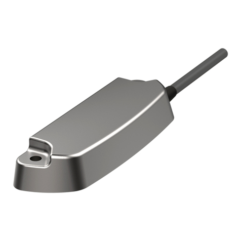
elobau
elobau 1655 V Series Quick guide

elobau
elobau 122 Series Quick guide
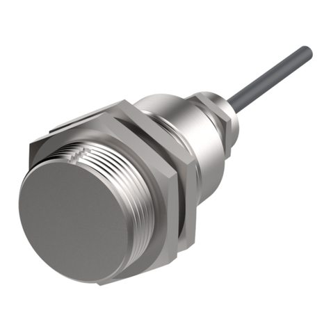
elobau
elobau 171 Series Quick guide

elobau
elobau UD30 350S Series User manual
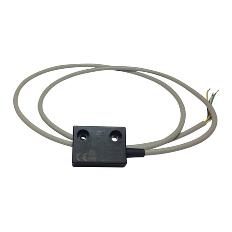
elobau
elobau 153 Series Quick guide
elobau
elobau NHT Series Quick guide

elobau
elobau eloProtect M 165MSK Series Quick guide
elobau
elobau N3 Series User manual
elobau
elobau 165 Series User manual

elobau
elobau 153 Series Quick guide

