EtiamPro HAA54 User manual

HAA54
V. 02 –27/04/2020 2 ©Velleman nv

HAA54
V. 02 –27/04/2020 3 ©Velleman nv
USER MANUAL
1. Introduction
To all residents of the European Union
Important environmental information about this product
This symbol on the device or the package indicates that disposal
of the device after its lifecycle could harm the environment. Do
not dispose of the unit (or batteries) as unsorted municipal
waste; it should be taken to a specialized company for recycling.
This device should be returned to your distributor or to a local
recycling service. Respect the local environmental rules.
If in doubt, contact your local waste disposal authorities.
Thank you for choosing EtiamPro! Please read the manual
thoroughly before bringing this device into service. If the device
was damaged in transit, do not install or use it and contact your
dealer.
The HAA54 employs “Double-Twin Optics”-technology and the
security logic is supplied by the ASIC-processor (Application
Specific Integrated Circuit), which was developed for this specific
application.
The Double-Twin Optics system combines two optical structures
and heat detectors in one housing. Both heat detectors are
equipped with a dual element that produces low-level noise only.
This enables the HAA54 to create a detection pattern that only
reacts to actual intruders and ignores pets or rodents.
The Double-Twin Optics system is controlled by the ASIC-
processor. This processor detects the change in polarity of a
signal caused by an intruder. Thanks to this technique, both
channels have a high degree of immunity against common radio
interference and power surges. This processor also provides the
HAA54 with a number of additional functions: digital pulse
counting, temperature compensation, warm-up delay, alarm
controls and an alarm activation delay. These characteristics
maximise security and provide excellent protection against false
alarm.

HAA54
V. 02 –27/04/2020 4 ©Velleman nv
2. Safety Instructions
Read and understand this manual and all safety signs before
using this appliance.
•This device can be used by children aged from 8 years and
above, and persons with reduced physical, sensory or
mental capabilities or lack of experience and knowledge if
they have been given supervision or instruction concerning
the use of the device in a safe way and understand the
hazards involved. Children shall not play with the device.
Cleaning and user maintenance shall not be made by
children without supervision.
3. General Guidelines
•Refer to the Velleman®Service and Quality Warranty on the
last pages of this manual.
•All modifications of the device are forbidden for safety
reasons. Damage caused by user modifications to the device
is not covered by the warranty.
•Only use the device for its intended purpose. Using the
device in an unauthorised way will void the warranty.
•Damage caused by disregard of certain guidelines in this
manual is not covered by the warranty and the dealer will
not accept responsibility for any ensuing defects or
problems.
•Nor Velleman nv nor its dealers can be held responsible for
any damage (extraordinary, incidental or indirect) –of any
nature (financial, physical…) arising from the possession,
use or failure of this product.
•Keep this manual for future reference.
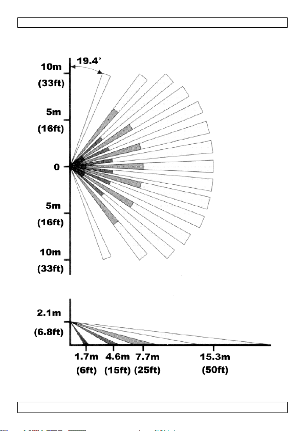
4. Detection Pattern
Please refer to page 2.

HAA54
V. 02 –27/04/2020 5 ©Velleman nv
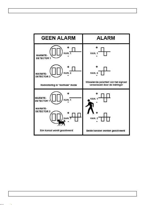
5. Double-Twin Optics System
Detection of changing polarity.

HAA54
V. 02 –27/04/2020 6 ©Velleman nv
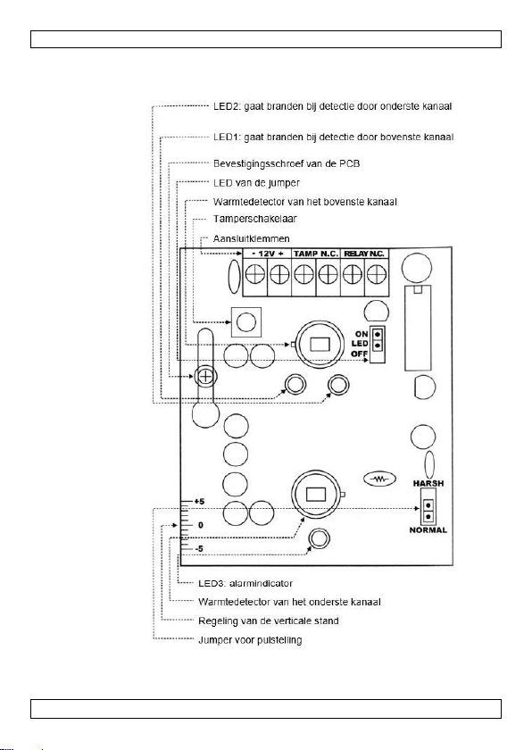
6. PCB Layout

HAA54
V. 02 –27/04/2020 7 ©Velleman nv
Terminal Block
12V
Connect the positive terminal (+) to a power
source of 9-16VDC on the alarm control panel.
Connect the negative terminal (-) to the
grounding point of the control panel.
TAMPER NC
Connect these terminals to a 24hr N.C.
(Normally Closed) protection zone of the alarm
control panel. The tamper switch contact is
closed if the detector’s front cover is in place.
The contact will open and an alarm signal will
instantly be sent to the control panel if the front
cover is removed at any time.
RELAY NC
This is the alarm output relay of the detector.
These two terminals should be connected to a
N.C. protection zone of the alarm control panel.
Jumper Settings
LED
Place the jumper in the “ON”-position to arm all
LEDs or place it in the “OFF”-position to
deactivate all LEDs. Detection is still possible
with the jumper in the “OFF”-position.
PULSE
Place the pulse count jumper in the “NORMAL”-
position for standard detection in a stable
environment. Place the pulse count jumper in
the “HARSH”-position for double detection within
12 seconds. Pets are ignored in this mode, which
is particularly useful if the device is installed in
an unstable environment.
LED Indicators
LED 1
“ON” upon detection by the upper channel
LED 2
“ON” upon detection by the lower channel
LED 3
“ON” when the alarm is activated, flashes during
the warm-up delay
Adjustment of the Vertical Angle
Loosen the fixing screw of the PCB in order to move the PCB up
or down. This enables the user to adjust both the detection angle
and the reach of the device while avoiding detection of small
(domestic) animals.
Heat Detectors
This device is equipped with two heat detectors for motion
detection. DO NOT TOUCH THE HEAT DETECTORS!

HAA54
V. 02 –27/04/2020 8 ©Velleman nv
7. Installation
Mounting Location
•The detector can be mounted on a flat surface (e.g. a wall)
or in a corner. Select a stable surface.
•This detector should only be used indoors and should be
installed in an environment that is shielded from the
elements.
•Do not expose the device to cold or warm air currents.
•Do not aim the detector at heating devices, air conditioning
vents, windows, refrigerator or freezer grilles or any other
surface that is subject to violent and sudden changes in
temperature.
•Do not place large objects in front of the detector, as this
will significantly diminish the area protected by the
detector’s beams.
•Select a mounting location that allows you to place the
detector at an angle of 45° (= optimal) with reference to the
intruder’s expected path. The detector should preferably be
mounted in a corner.
•Installation height: 2 to 3 m (7 to 10 ft).
Removing the Front Cover
1. Loosen the screw.
2. Insert the tip of a screwdriver into the latching slot and
release the front cover.
3. Remove the front cover.
Removing the PCB
The PCB should be removed before mounting the back cover.
1. Loosen the fixing screw of the PCB.
2. Push the PCB upward until the head of the screw will pass
through the opening.
3. Remove the PCB carefully.
Mounting the Back Cover
The back cover is suited for wall or corner mounting.
1. Feed the power cord through the push-out hole at the top
and on the inside of the back cover.
2. The push-out holes at the back are suitable for surface or
wall mounting. The ones at the sides are suitable for corner
mounting.
3. Mount the back cover.

HAA54
V. 02 –27/04/2020 9 ©Velleman nv
Mounting the Front Cover, Wiring
1. Reinsert the PCB and use the fixing screw to fix the PCB
firmly.
2. Connect the wires to the terminal block.
3. Replace the front cover and make sure the tamper switch is
depressed when the front cover is clicked into place. Close
the housing firmly with the fixing screw.
The Walk Test
1. The walk test can be performed as soon as the warm-up
delay is finished, in other words when the alarm LED stops
flashing. The walk test is necessary in order to verify
whether the device is in good working order and whether it
covers the desired area.
2. The alarm will sound when both the upper and lower
channels are triggered simultaneously when the jumper is
in the “NORMAL” position.
3. If the jumper is in the “HARSH” position, the alarm will
sound upon simultaneous and double activation of both
channels in a space of 12 seconds.
4. The detection range and the vertical angle of the device
can be adjusted by sliding the PCB up or down.
8. Technical Specifications
current consumption ........................... 15 mA typical at 12 VDC
operating voltage.............................9-16 VDC, 12 VDC nominal
detection method............... PIR detection with changing polarity,
.................................................“Double –Twin Optics” system
warm-up delay .......... 2 min. typical, with flashing LED indication
alarm activation delay .....................................................2-3 s
alarm output .......N.C. relay contact with a 10 resistor in series
................................................. contact rating: 28 VDC, 0.1 A
walk-test LEDs ............... upper/lower channels, alarm indicators
.............................................can be armed or disarmed at will
pulse counter ................................ normal response or 2 pulses
.............................................. within 12 s in “HARSH”-position
tamper switch ............ N.C. contact with a 10 resistor in series
................................................contact rating: 12 VDC, 50 mA

HAA54
V. 02 –27/04/2020 10 ©Velleman nv
operating temperature ....................................... -10 to +55 °C
humidity................................................ 95 % non-condensing
EMC .......................................... conform to CE-label standards
dimensions ................................ 64 (W) x 45 (H) x 127 (L) mm
Use this device with original accessories only. Velleman nv
cannot be held responsible in the event of damage or
injury resulting from (incorrect) use of this device. For
more info concerning this product and the latest version of
this manual, please visit our website www.velleman.eu.
The information in this manual is subject to change
without prior notice.
© COPYRIGHT NOTICE
The copyright to this manual is owned by Velleman nv. All
worldwide rights reserved. No part of this manual may be
copied, reproduced, translated or reduced to any electronic
medium or otherwise without the prior written consent of the
copyright holder.

HAA54
V. 02 –27/04/2020 11 ©Velleman nv
HANDLEIDING
1. Inleiding
Aan alle ingezetenen van de Europese Unie
Belangrijke milieu-informatie betreffende dit product
Dit symbool op het toestel of de verpakking geeft aan dat, als
het na zijn levenscyclus wordt weggeworpen, dit toestel schade
kan toebrengen aan het milieu. Gooi dit toestel (en eventuele
batterijen) niet bij het gewone huishoudelijke afval; het moet bij
een gespecialiseerd bedrijf terechtkomen voor recyclage. U moet
dit toestel naar uw verdeler of naar een lokaal recyclagepunt
brengen. Respecteer de plaatselijke milieuwetgeving.
Hebt u vragen, contacteer dan de plaatselijke autoriteiten
betreffende de verwijdering.
Bedankt dat u hebt gekozen voor Etiampro! Lees deze
handleiding grondig door voor u het toestel in gebruik neemt.
Werd het toestel beschadigd tijdens het transport, installeer het
dan niet en raadpleeg uw dealer.
De HAA54 gebruikt Double-Twin Optics-technologie en de
beveiligingslogica wordt geleverd door de ASIC-processor
(Application Specific Integrated Circuit), die speciaal voor deze
toepassing werd ontwikkeld.
Het Double-Twin Optics-systeem verenigt twee optische
structuren en twee warmtedetectors in één behuizing. Deze
warmtedetectors beschikken elk over een duo-element dat
weinig ruis produceert. Op deze manier wordt een
detectiepatroon gecreëerd dat enkel reageert op indringers en
dat huisdieren of knaagdieren negeert.
Het Double-Twin Optics-systeem wordt gestuurd door de ASIC-
processor, die zorgt voor detectie bij wisselende polariteit van
een signaal. Dankzij deze techniek hebben beide kanalen een
hoge weerstand tegen radiostoring en stroomstoten. Bovendien
beschikt de HAA54 dankzij deze processor ook nog over een
aantal andere functies: digitale pulstelling,
temperatuurcompensatie, inschakelvertraging en een
alarmuitgang en -regelingen. Deze kenmerken zorgen voor een
optimale veiligheid en vormen een uitstekende bescherming
tegen valse alarmmeldingen.

HAA54
V. 02 –27/04/2020 12 ©Velleman nv
2. Veiligheidsvoorschriften
Lees en begrijp deze handleiding en de veiligheidsinstructies vóór
ingebruikname.
•Dit toestel is geschikt voor gebruik door kinderen vanaf
8 jaar, door personen met fysieke, zintuiglijke of
verstandelijke beperkingen, of door personen met gebrek
aan ervaring en kennis, op voorwaarde dat dit onder
toezicht gebeurt van een persoon die verantwoordelijk is
voor hun veiligheid of hun aanwijzingen heeft gegeven, hoe
zij het toestel moeten gebruiken en zich bewust zijn van de
risico's die het gebruik van het toestel met zich meebrengt.
Kinderen mogen niet met het toestel spelen. De reiniging en
het onderhoud van het toestel mogen niet worden
uitgevoerd door kinderen, tenzij ze onder toezicht staan.
3. Algemene richtlijnen
•Raadpleeg de Velleman® service- en kwaliteitsgarantie
achteraan deze handleiding.
•Om veiligheidsredenen mag u geen wijzigingen aanbrengen.
Schade door wijzigingen die de gebruiker heeft aangebracht
aan het toestel valt niet onder de garantie.
•Gebruik het toestel enkel waarvoor het gemaakt is. De
garantie vervalt automatisch bij ongeoorloofd gebruik.
•De garantie geldt niet voor schade door het negeren van
bepaalde richtlijnen in deze handleiding en uw dealer zal de
verantwoordelijkheid afwijzen voor defecten of problemen
die hier rechtstreeks verband mee houden.
•Noch Velleman nv noch zijn verdelers kunnen aansprakelijk
gesteld worden voor schade (buitengewoon, incidenteel of
onrechtstreeks) –van welke aard dan ook (financieel,
fysisch…) voortvloeiend uit het bezit, gebruik of falen van dit
product.
•Bewaar deze handleiding voor verdere raadpleging.
4. Detectiepatroon
Raadpleeg pagina 2.
HAA54
V. 02 –27/04/2020 13 ©Velleman nv
5. Double-Twin Optics-systeem
Detectie van wisselende polariteit.
HAA54
V. 02 –27/04/2020 14 ©Velleman nv
6. Opmaak van de PCB

HAA54
V. 02 –27/04/2020 15 ©Velleman nv
Aansluitklemmen
12V
Verbind de positieve aansluitklem (+) met een
voedingsbron van 9-16 VDC op het
controlepaneel van het alarm. Verbind de
negatieve aansluitklem (-) met de aarding van
het controlepaneel.
TAMPER NC
Verbind deze aansluitklemmen met een N.C.
(Normally Closed = normaal gesloten) 24 u-zone
van het controlepaneel van het alarm. De anti-
inbraak schakeling is gesloten wanneer het
frontpaneel van de detector op zijn plaats zit.
Het contact gaat open en een alarmsignaal
wordt onmiddellijk verstuurd naar het
controlepaneel indien het frontpaneel wordt
verwijderd.
RELAY NC
Dit is het alarm uitgangsrelais van de detector.
Deze twee aansluitklemmen moeten worden
aangesloten op een N.C.-zone van het
controlepaneel van het alarm.
Regeling van de jumper
LED
Plaats de jumper in de “ON”-stand om alle leds
op scherp te stellen of plaats hem in de “OFF”-
stand om alle leds te deactiveren. Detectie is
nog steeds mogelijk indien de jumper zich in de
“OFF”-stand bevindt.
PULSE
Plaats de pulsteller in de “NORMAL”-stand voor
standaard detectie. Gebruik deze stand indien
het apparaat werd geïnstalleerd in een stabiele
omgeving. Plaats de pulsteller in de “HARSH”-
stand (“moeilijk”) voor dubbele detectie binnen
de 12 seconden. In deze stand worden
huisdieren genegeerd. Deze stand is bijzonder
nuttig indien het apparaat werd geïnstalleerd in
een “moeilijke” of onstabiele omgeving.
LED-indicators
LED 1
“ON” bij detectie door het bovenste kanaal
LED 2
“ON” bij detectie door het onderste kanaal
LED 3
“ON” bij alarmtoestand, knippert wanneer het
toestel aan het opwarmen is
Regelen van de verticale stand
Maak de bevestigingsschroef van de PCB los om de PCB naar
boven of beneden te schuiven. Zo kunt u de detectiehoek en de
detectieafstand aanpassen en kunt u detectie van bv. kleine
(huis)dieren vermijden.

HAA54
V. 02 –27/04/2020 16 ©Velleman nv
Warmtedetectors
Dit apparaat is uitgerust met twee warmtedetectors voor
bewegingsdetectie. RAAK DEZE DETECTORS NIET AAN!
7. Montage
Montageplaats
•De detector kan worden bevestigd aan de muur of in een
hoekje. Kies een stabiel oppervlak.
•Deze detector is uitsluitend bestemd voor gebruik
binnenshuis en moet worden geïnstalleerd in een omgeving
die beschermd is tegen de elementen.
•Installeer het apparaat niet in de buurt van warme of koude
luchtstromen.
•Richt de detector niet naar verwarmingselementen,
ventilatieroosters, ramen, roosters van koelkasten of
diepvriezers of naar andere oppervlakken die onderhevig
zijn aan plotse en hevige temperatuurwijzigingen.
•Plaats geen grote voorwerpen voor de detector: ze beperken
het detectiegebied.
•Kies een montageplaats die u toelaat om de detector te
gebruiken onder een hoek van 45° (optimaal) t.o.v. de
plaats waar de ongewenste bezoeker vermoedelijk het
beschermde gebied zal binnendringen. De detector wordt bij
voorkeur gemonteerd in een hoekje.
•Montagehoogte: 2 tot 3 m.
Verwijderen van het frontpaneel
1. Draai de schroef los.
2. Stop de punt van een schroevendraaier in de gleuf onder
de bevestigingsschroef van de behuizing en maak het
frontpaneel los.
3. Verwijder het frontpaneel.
Verwijderen van de PCB
Verwijder de PCB vóór u het achterpaneel monteert.
1. Maak de bevestigingsschroef van de PCB los.
2. Duw de PCB naar boven tot de kop van de schroef door de
opening kan.
3. Verwijder de PCB voorzichtig.

HAA54
V. 02 –27/04/2020 17 ©Velleman nv
Monteren van het achterpaneel
Het achterpaneel is geschikt voor montage op een plat oppervlak
of in een hoekje.
1. Stop de voedingskabel door de uitsparing bovenaan en aan
de binnenkant van het achterpaneel.
2. De uitsparingen aan de achterkant zijn geschikt voor
montage op een plat oppervlak. De uitsparingen aan de
zijkant zijn geschikt voor montage in een hoek.
3. Monteer het achterpaneel.
Bedrading en aanbrengen van het frontpaneel
1. Breng de PCB terug op zijn plaats en draai de
bevestigingsschroef stevig dicht.
2. Verbind de draden met de aansluitklemmen.
3. Breng het frontpaneel aan en zorg ervoor dat de anti-
inbraak schakelaar ingedrukt is wanneer u het frontpaneel
vastklikt. Draai de bevestigingsschroef stevig dicht om de
behuizing af te sluiten.
Test
1. U kunt de test uitvoeren zodra de alarm led niet meer
knippert, d.w.z. zodra de HAA54 is opgewarmd. Deze test
is noodzakelijk om na te gaan of de HAA54 bedrijfsklaar is
en om te bepalen of het toestel het gewenste
detectiegebied volledig bestrijkt.
2. Het alarm gaat af wanneer beide kanalen gelijktijdig
worden geactiveerd wanneer de jumper van de pulsteller in
de “NORMAL”-stand staat.
3. Wanneer de jumper van de pulsteller in de “HARSH”-stand
staat, gaat het alarm slechts af wanneer de beide kanalen
2 keer tegelijk worden geactiveerd binnen een tijdspanne
van 12 seconden.
4. U moet de PCB naar boven of beneden schuiven om het
detectiebereik en de verticale stand van de HAA54 aan te
passen.
8. Technische specificaties
stroomverbruik.................................. 15 mA typisch bij 12 VDC
werkspanning................................ 9-16 VDC, 12 VDC nominaal
detectiemethode.............. PIR detectie met wisselende polariteit,
...................................................Double-Twin Optics-systeem
opwarmingstijd............typisch : 2 minuten, met knipperende led
inschakelvertraging alarm................................................2-3 s
alarmuitgang................................................ N.C. relaiscontact
....................................... met een weerstand in serie van 10
.......................................................vermogen; 28 VDC, 0.1 A

HAA54
V. 02 –27/04/2020 18 ©Velleman nv
detectielleds.....................................onderste/bovenste kanaal,
................................................. kunnen worden uitgeschakeld
pulsteller ...................................normale respons of 2 impulsen
............................ binnen de 12 seconden in de “HARSH”-stand
antisabotageschakelaar .........................................N.C. contact
....................................... met een weerstand in serie van 10
..................................................... vermogen: 12 VDC, 50 mA
werktemperatuur.............................................. -10 tot +55 °C
vochtigheid ........................................ 95 % niet-condenserend
EMC ................................ conform de normen voor het CE-label
afmetingen .................................64 (B) x 45 (H) x 127 (L) mm
Gebruik dit toestel enkel met originele accessoires.
Velleman nv is niet aansprakelijk voor schade of
kwetsuren bij (verkeerd) gebruik van dit toestel. Voor
meer informatie over dit product en de laatste versie van
deze handleiding, zie www.velleman.eu. De informatie in
deze handleiding kan te allen tijde worden gewijzigd
zonder voorafgaande kennisgeving.
© AUTEURSRECHT
Velleman nv heeft het auteursrecht voor deze handleiding.
Alle wereldwijde rechten voorbehouden. Het is niet
toegestaan om deze handleiding of gedeelten ervan over te
nemen, te kopiëren, te vertalen, te bewerken en op te slaan op
een elektronisch medium zonder voorafgaande schriftelijke
toestemming van de rechthebbende.

HAA54
V. 02 –27/04/2020 19 ©Velleman nv
MODE D'EMPLOI
1. Introduction
Aux résidents de l'Union européenne
Informations environnementales importantes concernant
ce produit
Ce symbole sur l'appareil ou l'emballage indique que l’élimination
d’un appareil en fin de vie peut polluer l'environnement. Ne pas
jeter un appareil électrique ou électronique (et des piles
éventuelles) parmi les déchets municipaux non-sujets au tri
sélectif ; une déchetterie traitera l’appareil en question.
Renvoyer l'appareil à votre fournisseur ou à un service de
recyclage local. Respecter la réglementation locale relative à la
protection de l’environnement.
En cas de questions, contacter les autorités locales pour
élimination.
Merci d'avoir acheté un produit Etiampro! Lire attentivement le
présent mode d'emploi avant la mise en service de l’appareil. Si
l'appareil a été endommagé pendant le transport, ne pas
l’installer et consulter votre revendeur.
Le HAA54 utilise la technologie “Double-Twin Optics” et la logique
de sécurité est livrée par le processeur ASIC (Application Specific
Integrated Circuit), conçu spécialement pour cette application.
Le système Double-Twin Optics combine deux structures
optiques et deux détecteurs de chaleur dans un seul boîtier.
Chacun des détecteurs dispose de deux éléments jumelés qui ne
produisent qu’un léger bruissement. La combinaison de ces
éléments crée un mode de détection qui réagit uniquement en
cas d’intrusion et qui néglige les animaux domestiques et les
rongeurs.
Le système Double-Twin Optics est piloté par le processeur ASIC,
qui assure la détection lorsque le signal change de polarité.
Grâce à cette technique, les deux canaux ont une immunité
importante aux parasites et aux pointes de courant. Grâce au
processeur ASIC, le HAA54 dispose en plus d’une gamme
étendue de fonctions additionnelles : compteur numérique
d’impulsions, compensation de température, temporisation
d’activation, une sortie d’alarme et des réglages d’alarme. Ces
caractéristiques permettent d’optimaliser la sécurité et offrent
une protection plus qu’adéquate contre les fausses alertes.

HAA54
V. 02 –27/04/2020 20 ©Velleman nv
2. Consignes de sécurité
Lire et comprendre ce mode d'emploi et toutes les consignes de
sécurité avant d'utiliser l'appareil.
•Cet appareil peut être utilisé par des enfants âgés de 8 ans
et plus et des personnes manquant d’expérience et de
connaissances ou dont les capacités physiques, sensorielles
ou mentales sont réduites, si elles ont été formées et
encadrées quant à l'utilisation de l'appareil d'une manière
sûre et connaissent les risques encourus. Ne pas laisser les
enfants jouer avec l'appareil. Le nettoyage et l'entretien ne
doivent pas être effectués par des enfants sans surveillance.
3. Directives générales
•Se référer à la garantie de service et de qualité Velleman®
en fin de ce mode d'emploi.
•Toute modification est interdite pour des raisons de sécurité.
Les dommages occasionnés par des modifications par le
client ne tombent pas sous la garantie.
•N’utiliser l'appareil qu’à sa fonction prévue. Un usage
impropre annule d'office la garantie.
•La garantie ne se s’applique pas aux dommages survenus en
négligeant certaines directives de ce mode d'emploi et votre
revendeur déclinera toute responsabilité pour les problèmes
et les défauts qui en résultent.
•Ni Velleman SA ni ses distributeurs ne peuvent être tenus
responsables des dommages exceptionnels, imprévus ou
indirects, quelles que soient la nature (financière,
corporelle, etc.), causés par la possession, l’utilisation ou le
dysfonctionnement de ce produit.
•Garder ce mode d'emploi pour toute référence ultérieure.
4. Mode de détection
Se référer à la page 2.
Table of contents
Languages:
Other EtiamPro Security Sensor manuals


Popular Security Sensor manuals by other brands


EDS
EDS RK 75 B Technical manual

B.E.G.
B.E.G. LUXOMAT PD4-M-1C-SM Installation and operating instruction

elobau
elobau eloProtect M 165MSK Series Translation of the original operating instructions

Vishay
Vishay TSSP57P38 manual

Latchways
Latchways Latchways LadderLatch manual

Leviton
Leviton IPSD6 installation instructions