ETM Sigicom 770-PRO User manual

Manual
Copyright ©Sigicom AB Art.no
770-PRO
Cellular Signal Analyzer
Art no. 090-07700-0
Manual ver. A

Copyright ©Sigicom AB
1
Table of Contents
1. Introduction .............................................................................................. 3
1.1 Technical data ................................................................................ 3
1.2 Button configuration ...................................................................... 4
1.3 Device Menu Flowchart ................................................................. 5
1.4 Accessories ..................................................................................... 5
2. Device Info, Settings & Testing .............................................................. 6
2.1 SMS remote configuration ....................................................................... 6
2.2 System ............................................................................................ 7
2.2.1 Device Data ................................................................................ 8
2.2.2 Server Address ........................................................................... 8
2.2.3 Check for Firmware (FW) Updates ................................................ 8
Device will connect to the internet to check if the firmware is up to date. ..... 8
2.2.4 Restart Device ............................................................................ 8
2.3 Settings & test ................................................................................ 9
2.3.1 Select APN & Select User/Password ......................................... 9
2.3.2 Logging ...................................................................................... 9
3. Scanning ................................................................................................ 10
3.1 Scanning a signal .......................................................................... 10
3.2 Understanding Signal Parameters ................................................ 12
4. View, Test and Upload/Download Scans .............................................. 13
4.1 Communication Test .................................................................... 13
4.2 Upload Signal (Remote) ............................................................... 13
4.3 Download Signal (Local) ............................................................. 14
4.4 Current Network Data .................................................................. 14
5. Configuration Tool ................................................................................ 15
6. Appendix ................................................................................................ 17
7. Contact Information ............................................................................... 19

2 Copyright ©Sigicom AB
Developed originally by:
ETM Mätteknik (Now part of Sigicom AB)
Glasfibergatan 8
SE-125 45 ÄLVSJÖ
Sweden
Phone (Office): +46 8 449 97 50
Email: sales@etmiot.com

Copyright ©Sigicom AB
3
1. Introduction
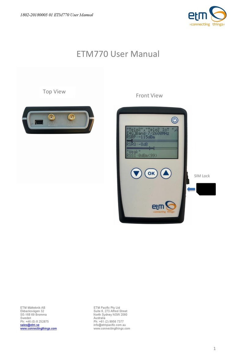
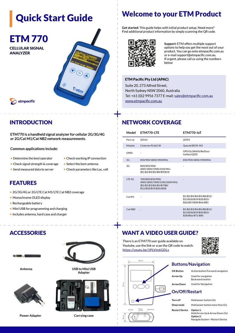
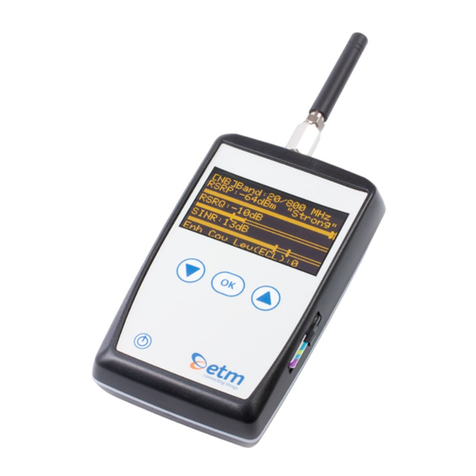
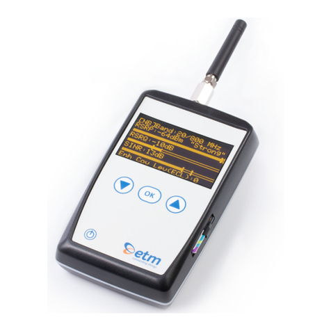
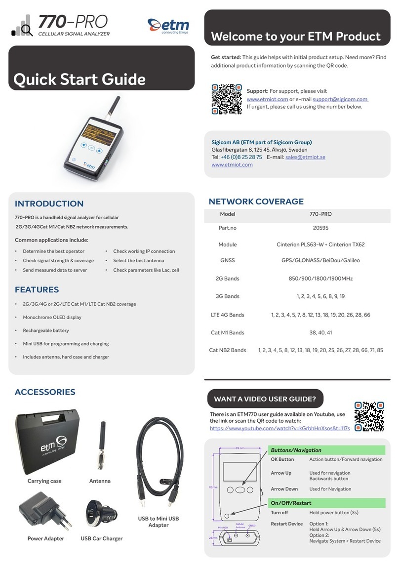
The 770-Pro is a tool used for analyzing cellular signals, originally
developed by ETM Mätteknik, which is now a part of Sigicom Group.
770-Pro was developed to support both Cat M1, NB as well as 4G,
3G, 2G technology while also providing GPS positioning together
with cellular data. The tool is battery powered and handheld for easy
carrying around.
1.1 Technical data
Model
770-Pro
Part.no
090-07700-0
Cellular
2G, 3G, 4G, Cat-M1, Cat NB1,2
GNSS (GPS)
GPS/BeiDou/GLONASS/Galileo
Frequencies/Bands
GSM/GPRS (2G) Frequencies:
850/900/1800/1900 MHz
UMTS (3G) Bands:
1, 2, 3, 4, 5, 6, 8, 9, 19
FDD-LTE (4G) Bands:
1, 2, 3, 4, 5, 7, 8, 12, 13, 18, 19, 20, 26, 28, 66
TD-LTE (4G) Bands:
38, 40, 41
FDD-LTE (M1, NB1, NB2) Bands:
1, 2, 3, 4, 5, 8, 12, 13, 18, 19, 20, 25, 26, 27,
28, 66, 71, 85
Dimension
115x69x28mm
Weight
130g
Battery
Lithium Polymer (LiPo) 3Ah
rechargeable
Battery lifetime
Scanning mode: More than 48 hours
Standby mode: More than 6 months
Screen
2,4 inch OLED 128x64px display
Operating temp.
-20°C to +55°C
Antenna
External SMA + Internal GNSS (GPS)
Interface
USB (Mini USB connector)

4 Copyright ©Sigicom AB
1.2 Button configuration
Action/Button
Explanation
Restart device
Hold Arrow down + up 5s or System à
Restart device in the device menu
Power OFF
Hold Power button 3s
Sleep mode
Hold Power button >5s
OK Button
Navigation
Arrow Up
Navigation, doubles as backwards button
at top of menu
Arrow Down
Navigation

Copyright ©Sigicom AB
5
1.3 Device Menu Flowchart
Flowchart showing the entire menu navigation of the tool.
1.4 Accessories
The 770-Pro comes with a carrying case containing USB cable for
programming/charging, charging brick, power adapters, car charger
and quick start guide.

6 Copyright ©Sigicom AB
2. Device Info, Settings & Testing
2.1 SMS remote configuration
SMS COMMANDS
EXPLANATION AND EXAMPLE
ET-IP1=”IP
Address”:”Port”
Change the server address
Example: ET-IP1=54.77.219.177:7162 (EWO server)
ET-IP3=”IP
Adress”:”Port”
Change the PING address
Example: ET-IP3=8.8.8.8:80 (Google)
ETSAPN=“List
position”, “APN name”
Change APN list
Example: ETSAPN=1,m2m.tele2.com
ETSUP=“List position”,
“Username”, “Password”
Change User/Password
Example: ETSUP=1,username1,password23

Copyright ©Sigicom AB
7
2.2 System

8 Copyright ©Sigicom AB
2.2.1 Device Data
Firmware version (TOP)
Hardware number (HW#)
IMEI Number
Date and Time
Module Temperature
Supply Voltage
Battery Voltage
Rolling network Information
2.2.2 Server Address
Add a server to receive data being sent from the device. This can be
configured in the configuration tool shown below or via SMS command
shown above.
Note! The values sent by the devices will be in raw format.
2.2.3 Check for Firmware (FW) Updates
Device will connect to the internet to check if the firmware is up to date.
2.2.4 Restart Device
Restart the device without using buttons.

Copyright ©Sigicom AB
9
2.3 Settings & test
2.3.1 Select APN & Select User/Password
Select which APN to use. APN can be added using the configuration tool
shown below, or via SMS command shown above. The same principle goes
for User and password.
2.3.2 Logging
Log interval is where you activate automatic continuous logging of the signal
measurements. This is also where you specify the interval between logs.
Send interval determines how often the logged data gets transmitted to a
server. The server address can be setup via configuration tool or SMS
command.

10 Copyright ©Sigicom AB
3. Scanning
3.1 Scanning a signal
Step 1: Select Radio Bands
Broaden or narrow down your network scanning to only the bands you wish
to scan.
Note! Before selecting radio bands, please check what bands are
available in your country/used by your SIM-card provider. Searching
for inactive bands lead to negative results.
Step 2: Scan for available operators
This might take a few minutes. The device displays all operators it can find in
your area together with a network technology (e.g. 4G or M1)

Copyright ©Sigicom AB
11
Step 3: Scanning a signal
Explanation
The device is connected to a 4G band. The band is 7 and the frequency is
2600 MHz.
RSRP - Reference Signal Received Power (the signal strength without noise
and interference)
measured in decibel meter (dBm). The signal is visualized in the signal bar
below the data.
RSRQ Reference Signal Received Quality (how well the signal is coded)
measured in decibel (dB). The signal
is visualized in the signal bar below the data.
In the bottom shows rolling information about PLMN & Band, Operator,
RSSI, Status (abbreviations explained under appendix).

12 Copyright ©Sigicom AB
3.2 Understanding Signal Parameters
PARAMETER
RSSI
SINR
RSRQ
RSRP
EC/IO
Tec hnology
LTE &
3G
LTE
LTE
LTE
HSPA+ &
EVDO
Excellent
> -65
> 12,5
> -5
> -84
> -2
Good
-65 to -
75
10 to
12.5
-9 to -
5
-85 to -
102
-2 to -5
Fair
-75 to -
85
7 to 10
-12 to
-9
-103 to -
111
-5 to -10
Poor
< -85
< 7
< -12
< -111
<-10
Short
Full
Explanation
RSSI
Reference signal
strength indicator
An average of the signal strength recieved.
SINR
Signal-to-
interference-plus-
noise ratio
Indicates the amount of interference
and noise in the signal.
RSRP
Reference Signal
Received Power
Similar to RSSI, but using a reference
signal to compare cells.
RSRQ
Reference Signal
Received Quality
Measuring signal quality based on RSSI

Copyright ©Sigicom AB
13
4. View, Test and Upload/Download Scans
Explanation
Band 7 / 2600 MHz
Referenced Signal Received Power (RSRP) is -82 dBm with Min & Max
values below.
Referenced Signal Received Quality (RSRQ) is -7dB with Min & Max values
below.
Public Land Mobile Network (PLMN) is 240007: The channel is 2850.
Scanned Network (Operator)
4.1 Communication Test
Ping to test network communication. Standard is set to Google’s server. This
can be change using the configuration tool shown below.
4.2 Upload Signal (Remote)
Uploading a signal is made through pushing “Send Data to Server” (See 2.2
Menu flowchart). Make sure you have IP + Port setup. You can easily add
this by sending a SMS command seen above in 2.1 SMS Commands.
Uploading signals continuously without pushing can be done through
activating logging and sending under settings.

14 Copyright ©Sigicom AB
4.3 Download Signal (Local)
If logging is turned on while sending is turned off, the logged scans will be
stored on the device. They can be downloaded using the configuration tool
explained further down the manual.
4.4 Current Network Data
Abbreviations described under appendix at the bottom of this manual.
*Press Arrow Down to access next page
Basic network data information.
Neighboring cells
SIM Status, Network Status, Net
Provider and
APN and LIP (Local IP Adress)

Copyright ©Sigicom AB
15
5. Configuration Tool
Another way of configuring your ETM770 is by using the configuration tool.
Begin by downloading the latest configuration tool located under Resources
on https://etmiot.com/. Proceed by connecting the unit to a computer with the
provided USB charging cable.
1. Start the configuration tool and connect the device to a PC running
Windows.
2. Go to the terminal tab, press “Set COM Port” to choose the right COM
port (see device manager, COM Ports. If no COM port shows up, make
sure the drivers got properly installed to your computer when the 770-
Pro was pluggeg in. When correct port is selected, set baud rate to
115200.
3. Open the port by pressing “COM(X): CLOSED”.
4. Click anywhere in the black terminal window until you see a flashing
square. Proceed by restarting the unit by either holding down arrow UP
and DOWN for 5 seconds, or write “ETESC” in the command window.
5. Make sure that the firmware matches the configuration tool version
unlike the picture above. Above, the config tool says CT09.80 in the
name, but the terminal window shows the device having FW to match
CT09.50.

16 Copyright ©Sigicom AB
1. When done configuring the unit, press the red button “WRITE
MEMORY” to upload the configuration to the unit.
2. To see what configuration is already on the unit, press “READ
MEMORY” when having the unit connected to the computer to read it
onto the configuration tool.
3. To save your configuration to use for future devices, press “File” in the
top left corner, then “save” in the dropdown menu and save the file to an
optional location. Make sure it’s saved as a .ctx file.

Copyright ©Sigicom AB
17
6. Appendix
Table below shows a brief explanation of the 3G network abbreviations.
ABBREVIATION
FULL
EXPLANATION
CHANN
CHANNEL
Shows the ARFCN (Absolute Frequency
Channel Number) of the Radio Band
Frequency.
PSC
Primary
Synchronization
Code
Describes start and stop time for the time
slot that the device has been allocated.
MCC
Mobile Country
Code
The first part of the PLMN code.
MNC
Mobile Network
Code
The second part of the PLMN code.
EC/n0
Carrier to Noise
Ratio
LAC
Local Area Code
CELL
CELL ID
Cell identification number
APN
Access Point
Name
This will only be useful information if
you have set up an ISP connection.
LIP
Local IP
This will only be useful information if
you have set up an ISP connection.
RSCP
Received Signal
Code Power
Measured in dBm
SQ
Signal Quality
Quality value for base station selection in
dBm
SRxL
RX level value for base station selection
indBm

18 Copyright ©Sigicom AB
Table below shows a brief explanation of the 4G network abbreviations.
ABBREVIATION
FULL
EXPLANATION
EARFCN
CHANNEL
E-UTRA Absolute Radio Frequency
Channel Number
B (Band)
Frequency Band
E-UTRA frequency band
DL
DL bandwidth
DL bandwidth
UL
UL bandwidth
UL bandwidth
Mode
Duplex Mode
TimeDivisionDuplex (TDD) or
FrequencyDivisionDuplex (FDD)
MCC
Mobile Country
Code
The first part of the PLMN code.
MNC
Mobile Network
Code
The second part of the PLMN code.
TAC
Tracking Area
Code
GCID
Global Cell ID
Global Cell ID
PhyC ID
Physical Cell ID
Physical Cell ID
SQ
Signal Quality
Quality value for base station selection in
dBm
RSRP
Reference Signal Received Power
RSRQ
Reference Signal Received Quality
RSSI
Reference Signal Strength Indication
Note: A PLMN is identified by the Mobile Country Code (MCC) and
the Mobile Network Code (MNC)

Copyright ©Sigicom AB
19
7. Contact Information
• Adress
Sigicom AB
Glasfibergatan 8
SE-125 45 ÄLVSJÖ
Sweden
• Phone
+46 8 44 99 770
• Website
www.etmiot.com
www.sigicom.com
• E-mail
Other manuals for Sigicom 770-PRO
1
Table of contents
Other ETM Measuring Instrument manuals
Popular Measuring Instrument manuals by other brands

Kensington
Kensington KS-PH-221-DELUXE user manual

Milwaukee
Milwaukee SM106 user manual
socomec
socomec DIRIS A20 operating instructions

Precision Digital Corporation
Precision Digital Corporation PD6908 instruction manual

Astute Medical
Astute Medical ASTUTE140 user manual

Zensol
Zensol TAP-4 troubleshooting guide
