ETM ETM770-7 User manual

1
For Support Contact +46 8 25 28 75, [email protected] or +61 2 9956 7377, [email protected]
Top View
USER
GUIDE
ETM770-7
CELLULAR NETWORK MONITORING TOOL
2G/3G/4G
1802–20180005 Rev PA1, 2021-02-08
Features:
•
Cat 4G & 3G Connectivity
•
2G (GSM/EGPRS) Connectivity
•
Select the most suitable antenna
•
OLED display
•
Send measured data to EWO server
•
Rechargeable battery
•
Sleep Mode for super low power
consumption
•
Includes antenna, hard case and
charger

2
For Support Contact +46 8 25 28 75, [email protected] or +61 2 9956 7377, [email protected]
WHAT DO YOU WANT TO DO?
1. Buttons, Navigation & Accessories ............................................................................................ 3
1.1 Buttons and Navigation ........................................................................................................... 3
1.2 Accessories ............................................................................................................................. 4
2. Configuration and settings .......................................................................................................... 4
2.1 SMS Commands ..................................................................................................................... 4
2.2 Configuration Tool ................................................................................................................... 5
2.3 System menu .......................................................................................................................... 6
2.3.1 Device Data ......................................................................................................................... 6
2.3.2 Select APN .......................................................................................................................... 7
2.3.3 Select User/Password for ISP ............................................................................................. 7
2.3.4 See Server Adress .............................................................................................................. 7
3. Scanning and uploading signals ................................................................................................. 8
3.1 Step 1: Select Radio Bands .................................................................................................... 8
3.2 Step 2: Scan for available operators ....................................................................................... 8
3.3 Step 3: Scanning a signal ....................................................................................................... 8
3.4 View, test and upload a signal ................................................................................................ 9
Appendix ........................................................................................................................................... 10

3
For Support Contact +46 8 25 28 75, [email protected] or +61 2 9956 7377, [email protected]
1. BUTTONS, NAVIGATION &
ACCESSORIES
• Insert SIM card as shown in the images above.
IMPORTANT! Make sure the SIM card has PIN code DISABLED!
• To charge the ETM770, insert the charger into the mini USB connector. The
battery is charged with 5V.
• Connect the same cable to a computer if you want to configure the ETM770
using the configuration tool.
1.1 Buttons and Navigation
ACTION/BUTTON
EXPLANATION
Restart Device
Alternative 1:
Hold Arrow DOWN + Arrow UP (5 seconds)
Alternative 2:
Navigate (System > Restart Device) in the device menu
Power OFF
Hold Power button (bottom left corner) 3 seconds
Sleep mode
Hold Power button more than 5 seconds
OK Button
Action button/Forward navigation in menu
Arrow Up
Menu navigation/Backwards button when at the top of the menu
Arrow Down
Menu navigation

4
For Support Contact +46 8 25 28 75, [email protected] or +61 2 9956 7377, [email protected]
1.2 Accessories
• The ETM770 comes with a carrying case containing: USB cable for
programming/charging, charging brick, power adapters, car charger and quick
start guide.
2. CONFIGURATION AND
SETTINGS
2.1 SMS Commands
• An easy way to configure the ETM770 is by sending commands via SMS to
the connected SIM card. Below is a table of commands and examples for
different configuration options.
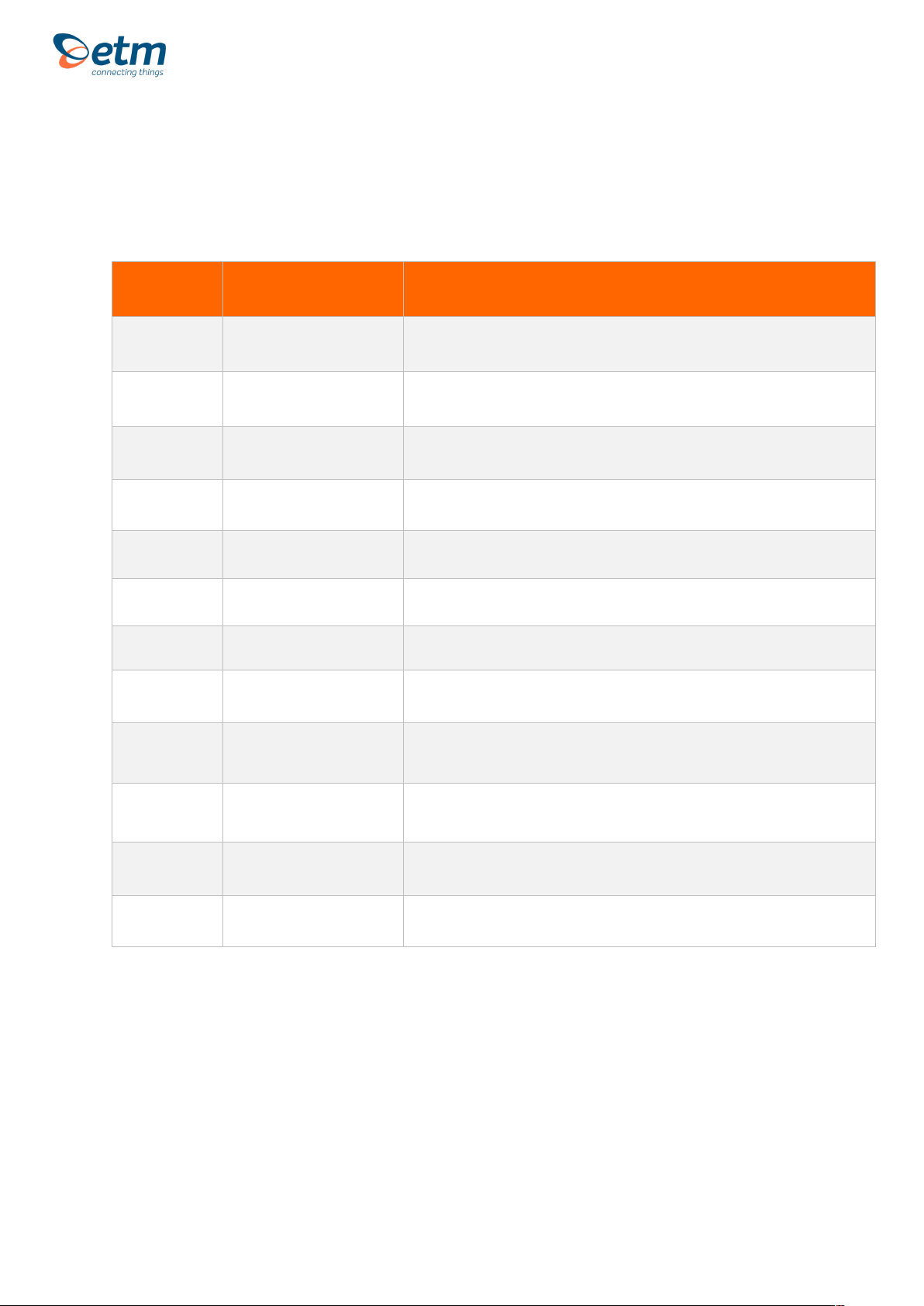
SMS COMMAND
EXPLANATION AND EXAMPLE
ET-IP1=”IP Address”:”Port”
Change the server address
Example: ET-IP1=54.77.219.177:7162 (EWO server)
ET-IP3=”IP Address”:”Port”
Change the PING address
Example: ET-IP3=8.8.8.8:80 (Google)
ETSAPN=“List position”, “APN
name”
Change APN list
Example: ETSAPN=1, m2m.tele2.com
ETSUP=“List position”,
“Username”, “Password”
Change User/Password
Example: ETSUP=1,username1,password23

5
For Support Contact +46 8 25 28 75, [email protected] or +61 2 9956 7377, [email protected]
2.2 Configuration Tool
• Another way of configuring your ETM770 is by using the configuration tool.
Begin by downloading the latest configuration tool located in the ETM770
product page on the https://etmiot.com/ website. Then proceed by connecting
the unit to a computer with the provided USB charging cable.
1. Start the configuration tool
2. Connect the unit to your computer
3. Go to the terminal tab, use “Set COM Port” to choose the right COM port (most likely
not COM1) and set the baud rate to 115200
4. Open the port by pressing “COM(X): CLOSED”
5. Click anywhere in the black terminal window until you see a flashing square. Proceed
by starting restarting the unit by either holding down arrow UP and DOWN for 5
seconds, or write “ETesc” in the command window.
6. Make sure that the firmware matches the configuration tool version unlike the
picture above (Should be CT0980, not CT0950 in this case)
7. The unit is now ready to be configured
1. When done configuring the unit, press the red button “WRITE MEMORY” to upload
the configuration to the unit
2. To see what configuration is already on the unit, press “READ MEMORY” when
having the unit connected to the computer to read it onto the configuration tool.
3. To save your configuration to use for future units, press “File” in the top left corner,
then “save” in the dropdown menu, and save the file to an optional location.
4. Your unit is now ready use.
3.
3.
3.
4.
5.
6.
6.
3.
2.
1.

6
For Support Contact +46 8 25 28 75, [email protected] or +61 2 9956 7377, [email protected]
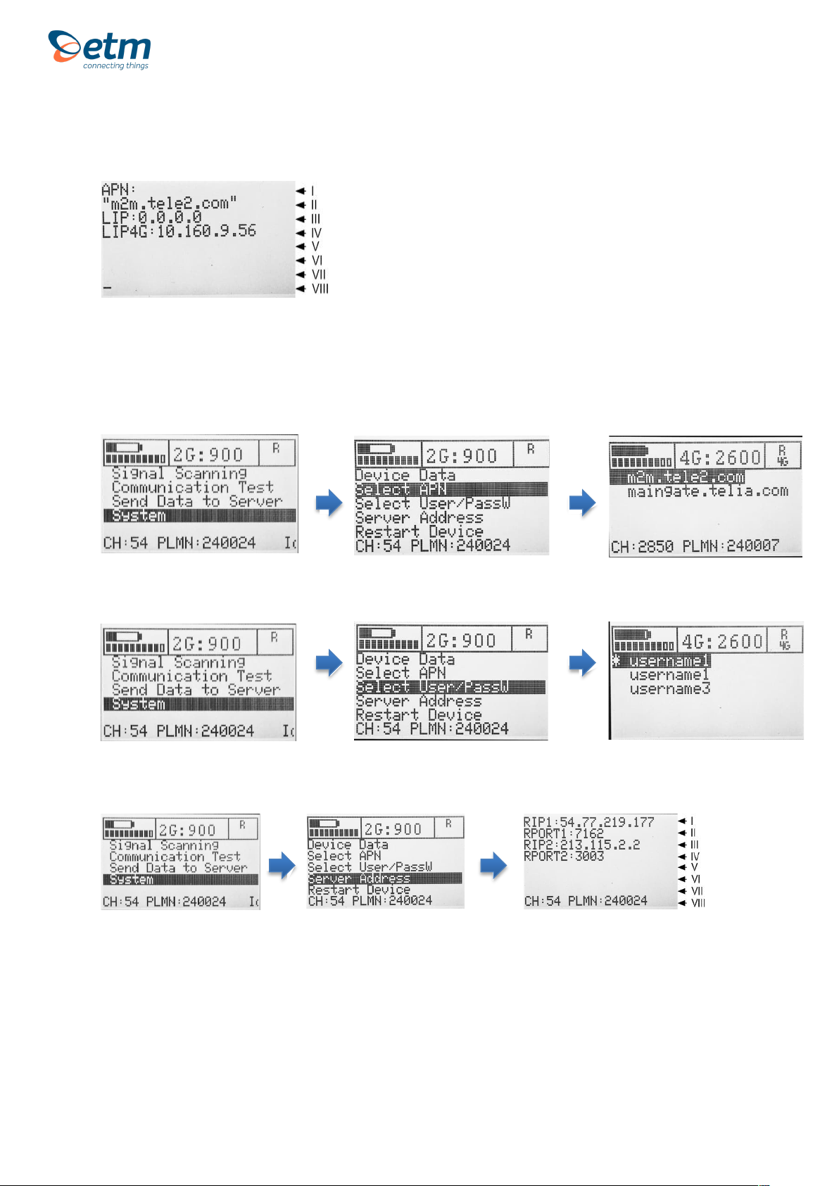
2.3 System menu
2.3.1 Device Data
I. SIM card ID number (SCID)
II. Device FW ID number
III. Device HW number
IV. IMEI number
V. Empty space
VI. Empty space
VII. Empty space
VIII. Different data rolls in the bottom bar. CH, PLMN, the scanned network and RSSI
1. If you press the down arrow once you will get a picture that looks similar to the
one below:
Monitoring Neighbour Cells
I. Number of Neighbour Cells found
II. Neighbour Cell 1
III. Neighbour Cell 2
IV. Neighbour Cell 3
V. Neighbour Cell 4
VI. Neighbour Cell 5
VII. Neighbour Cell 6
VIII. Different data rolls in the bottom bar. CH, PLMN, the scanned network and RSSI.
2. If you press the down arrow once again you will get the following:
I. SIM status
II. Registration status
III. “Network provider(EONS):” (Info text string)
IV. Network provider
7
For Support Contact +46 8 25 28 75, [email protected] or +61 2 9956 7377, [email protected]
3. Press the down button again and you will have gotten all the network
information available:
I. “APN:” (Info text string)
II. APN
III. Local IP Address
IV. Local IP Address 4G/LTE
2.3.2 Select APN
2.3.3 Select User/Password for ISP
2.3.4 See Server Adress
I. Remote IP address 1
II. Remote Port 1
III. Remote IP address 2
IV. Remote Port 2
V. Empty space
VI. Empty space
VII. Empty space
Different data rolls in the bottom bar. CH, PLMN, the scanned network and RSSI
Device Data Menu
8
For Support Contact +46 8 25 28 75, [email protected] or +61 2 9956 7377, [email protected]
3. SCANNING AND
UPLOADING SIGNALS
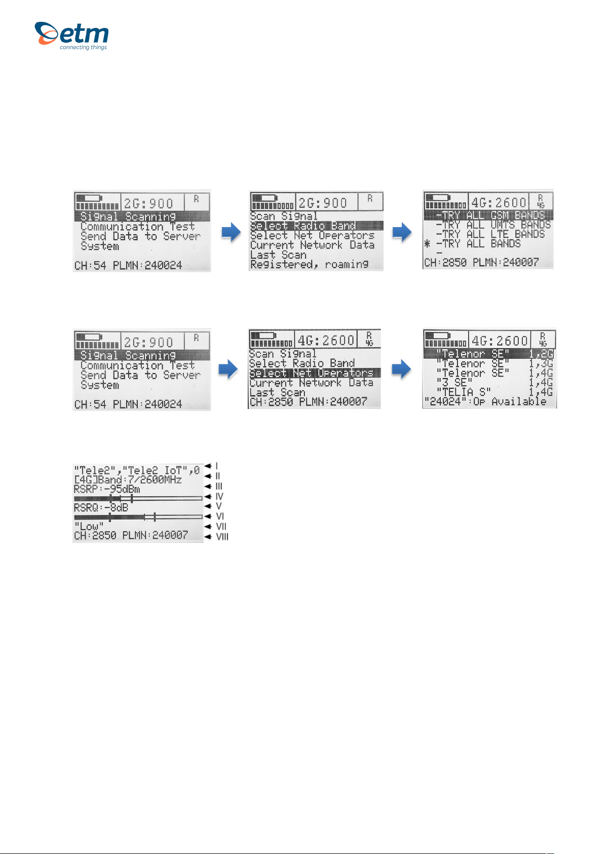
3.1 Step 1: Select Radio Bands
3.2 Step 2: Scan for available operators
3.3 Step 3: Scanning a signal
I. Scanned network.
II. The device is connected to a 4G band. The band is 7 and the frequency is 2600 MHz.
III. Reference Signal Received Power (the signal strength without noise and interference)
measured in dBm. The signal is visualized in the signal bar below the data.
IV. Signal Quality Bar.
V. Reference Signal Received Quality (how well the signal is coded) measured in dB. The signal
is visualized in the signal bar below the data.
VI. Signal Quality Bar.
VII. Signal Quality (Weak, Low, Medium, High or Strong)

9
For Support Contact +46 8 25 28 75, [email protected] or +61 2 9956 7377, [email protected]
3.4 View, test and upload a signal
See last scan
I. Scanned network.
II. Referenced Signal Received Power (RSRP) is -91 dBm.
III. RSRP Min and Max values in -dBm
IV. Referenced Signal Received Quality (RSRQ) is -7dB.
V. RSRQ Min and Max values in -dBm
VI. Tracking Area Code: Global Cell ID
VII. Public Land Mobile Network (PLMN) is 240007: The channel is 2850
VIII. Scanned network.
Testing signal
Upload signal
Current network data
I. The
channel is 2850 and the frequency is 2600 MHz.
II. E-UTRA frequency band: Download bandwidth: Upload bandwidth
III. Mobile Country Code (first part of the PLMN code): Mobile Network Code (second part of the
PLMN code)
IV. FDD or TDD: Physical Cell ID
V. Reference Signal Received Power (RSRP) is -91 dBm.
VI. Reference Signal Received Quality (RSRQ) is -7 dB
VII. Tracking Area Code: Global Cell ID
VIII. The channel is 2850: Public Land Mobile Network (PLMN) is 240007
10
For Support Contact +46 8 25 28 75, [email protected] or +61 2 9956 7377, [email protected]
Appendix
1. Table below shows a brief explanation of the 3G network abbreviations.
ABBREVIATION
FULL NAME
FURTHER EXPLANATIONS
CHANN
CHANNEL
Shows the ARFCN (Absolute Frequency Channel Number) of the Radio Band
Frequency.
PSC
Primary Synchronization
Code
Describes start and stop time for the time slot that the device has been allocated.
MCC
Mobile Country Code
The first part of the PLMN code.
MNC
Mobile Network Code
The second part of the PLMN code.
EC/n0
Carrier to Noise Ratio
LAC
Local Area Code
CELL
CELL ID
Cell identification number
APN
Access Point Name
This will only be useful information if you have set up an ISP connection.
LIP
Local IP
This will only be useful information if you have set up an ISP connection.
RSCP
Received Signal Code
Power
Measured in dBm
SQ
Signal Quality
Quality value for base station selection in dBm
SRxL
RX level value for base station selection indBm
11
For Support Contact +46 8 25 28 75, [email protected] or +61 2 9956 7377, [email protected]
2. Table below shows a brief explanation of the 4G network abbreviations.
ABBREVIATION
FULL NAME
FURTHER EXPLANATIONS
EARFCN
CHANNEL
E-UTRA Absolute Radio Frequency Channel Number
Band
Frequency Band
E-UTRA frequency band
DL
DL bandwidth
DL bandwidth
UL
UL bandwidth
UL bandwidth
Mode
Duplex Mode
TimeDivisionDuplex (TDD) or FrequencyDivisionDuplex (FDD)
MCC
Mobile Country Code
The first part of the PLMN code.
MNC
Mobile Network Code
The second part of the PLMN code.
TAC
Tracking Area Code
GCID
Global Cell ID
Global Cell ID
PhyC ID
Physical Cell ID
Physical Cell ID
SQ
Signal Quality
Quality value for base station selection in dBm
RSRP
Reference Signal Received Power
RSRQ
Reference Signal Received Quality
Note: A PLMN is identified by the Mobile Country Code (MCC) and the Mobile Network Code (MNC)
ETM Mätteknik AB
Ekbacksvägen 32, SE-168 69 Bromma, Sweden
Tel: +46 (0)8 25 28 75 Fax: +46 (0)8 80 11 10
Email: [email protected] Web: www.etm.se
ETM Pacific Pty Ltd
Suite 6, 273 Alfred Street, North Sydney NSW 2060, Australia
Tel: +61 (0)2 9956 7377 Fax: +61 (0)2 9956 5791
Email: [email protected] Web: www.etmiot.com.au
Table of contents
Other ETM Measuring Instrument manuals


Popular Measuring Instrument manuals by other brands


Eaton
Eaton POW-R-COMMAND 1000 user guide

socomec
socomec COUNTIS E27 instruction manual

PCB Piezotronics
PCB Piezotronics 355M73 operating guide

Hydrotechnik
Hydrotechnik MultiControl 4070 operating instructions

ThermoWorks
ThermoWorks ThermaQ 2 operating instructions

BRUEL & KJAER
BRUEL & KJAER 2976 instruction manual


