ETM DeltaBlue User manual

For Support Contact: +61 2 9956 7377 or
sales@etmiot.com.au
1802-20200008 RevA, 2020-03-04 ANZ
USER
GUIDE
Features:
•Up to 3 years battery life time
•Integrated 7-channel data logger
•Integrated 2G/3G/4G wireless modem
•Integrated GPS, temperature, humidity,
pressure sensor and accelerometer
•Pre-configured for the most common
sensor types with 3.6V, 5V & 16V power
feed
•Easy access to logged measurements via
ETM’s IoT Cloud Dashboard (EWO)
•Delivered with battery, SIM card &
integrated GSM and GPS antennas
•Easy integration to SCADA and telemetry
systems
ETM DELTABLUE
OUTDOOR AND BATTERY-POWERED REMOTE
MONITORING, ALARMING & LOGGING SOLUTION

For Support Contact: +61 2 9956 7377 or
sales@etmiot.com.au
TABLE OF CONTENTS
Introduction...................................................................................................................................................... 5
Nomenclature ................................................................................................................................................ 5
Overview........................................................................................................................................................ 5
Physical Dimensions...................................................................................................................................... 6
Specifications................................................................................................................................................. 6
Battery............................................................................................................................................................ 8
I/O Connector –ETM DeltaBlue I/O, I/O GPS............................................................................................... 9
I2C Sensor –ETM DeltaBlue I/O, I/O GPS................................................................................................. 11
Internal Module............................................................................................................................................ 12
Internal Sensors........................................................................................................................................... 13
Indicator LEDs ............................................................................................................................................. 15
Green status LEDs ...................................................................................................................................... 15
Yellow signal strength LEDs........................................................................................................................ 15
Configuration Tool......................................................................................................................................... 17
Installation.................................................................................................................................................... 17
Using the Right Version of the Configuration Tool ...................................................................................... 17
Using the Configuration Tool....................................................................................................................... 18
Saving, reading and writing configuration files............................................................................................ 19
General Settings tab...................................................................................................................................... 20
Phone number to SMS Alarm recipients ..................................................................................................... 20
Analogue Values.......................................................................................................................................... 20
Unit ID added to messages ......................................................................................................................... 20
GPS settings................................................................................................................................................ 21
Miscellaneous.............................................................................................................................................. 21
HW Model No - HW Serial No ..................................................................................................................... 22
Init AT/ET-Command Table......................................................................................................................... 22
Alarm messages.......................................................................................................................................... 22
Real Time Clock Sync ................................................................................................................................. 22
Channels tab .................................................................................................................................................. 23
Open→Close(N.O) Alarm Message ............................................................................................................ 23
Close→Open(N.C) Alarm Message ............................................................................................................ 23
Digital I/O alarm........................................................................................................................................... 23
Port .............................................................................................................................................................. 23
SMS Phone Number.................................................................................................................................... 23
Alarm (port 2200)......................................................................................................................................... 24
ET-cmd sending........................................................................................................................................... 24
Alarm delay.................................................................................................................................................. 24
Restore delay............................................................................................................................................... 24
Analogue Input Alarm.................................................................................................................................. 24

For Support Contact: +61 2 9956 7377 or
sales@etmiot.com.au
Alarm message............................................................................................................................................ 26
Power in Low Level...................................................................................................................................... 26
Analogue Input Alarm.................................................................................................................................. 26
Data Transfer / Logging / Timers tab........................................................................................................... 27
Common settings for all channels ............................................................................................................... 27
Setting the SWT timers................................................................................................................................ 29
Data Logging (SWT1).................................................................................................................................. 29
Data logging............................................................................................................................................. 29
Pulse Counting Transition........................................................................................................................ 29
Periodicity ................................................................................................................................................ 29
Channel selection .................................................................................................................................... 30
Send interval logged data (SWT2) .............................................................................................................. 30
Monitoring data (SWT3)............................................................................................................................... 30
Monitoring data (SWT4)............................................................................................................................... 30
Wake up interval low power (SWT5) ........................................................................................................... 30
What you should know about the Low Power Mode ............................................................................... 31
Heart Beat package..................................................................................................................................... 32
Communication tab ....................................................................................................................................... 34
Remote Server............................................................................................................................................. 34
ISP Dial up Login......................................................................................................................................... 34
Connected to ISP or Server......................................................................................................................... 35
Firewall......................................................................................................................................................... 35
Internal Serial –setting the baud rate.......................................................................................................... 36
Logged data tab............................................................................................................................................. 37
Channel values............................................................................................................................................ 37
Alarm History Viewer ................................................................................................................................... 37
Logged data................................................................................................................................................. 37
Terminal tab ................................................................................................................................................... 38
Entering command mode............................................................................................................................. 38
Send buttons................................................................................................................................................ 38
Set RTC....................................................................................................................................................... 39
Reprogram using CSD................................................................................................................................. 39
Channel Scaling tab ...................................................................................................................................... 40
Application examples.................................................................................................................................... 41
Basic I/O Control............................................................................................................................................ 41
Wiring Diagram............................................................................................................................................ 41
Configuration Tool Settings ......................................................................................................................... 42
Temperature sensor ...................................................................................................................................... 43
Wiring Diagram............................................................................................................................................ 43
Configuration Tool Settings for temperature logging and alarm.................................................................. 44
Tank level Monitoring with 4-20mA Sensor................................................................................................ 46

For Support Contact: +61 2 9956 7377 or
sales@etmiot.com.au
Wiring Diagram............................................................................................................................................ 46
Tank Level Monitor with Rochester Gauge................................................................................................. 47
Water/Electrical Meter Measurement........................................................................................................... 48
Pressure Sensor ............................................................................................................................................ 49
Control Via ET Commands ........................................................................................................................... 50
General commands ..................................................................................................................................... 50
I/O commands ............................................................................................................................................. 51
SMS commands .......................................................................................................................................... 51
Pulse input commands ................................................................................................................................ 52
Internet commands...................................................................................................................................... 52
Other commands ......................................................................................................................................... 53

For Support Contact: +61 2 9956 7377 or
sales@etmiot.com.au
INTRODUCTION
Nomenclature
The DeltaBlue incorporates the Cinterion PLS62-W module and is intended for worldwide
use (network and regulatory approvals permitting).
Overview
DeltaBlue is a battery-powered, rugged device, which is used for measuring and control of
remote areas or installations without access to mains power or fixed communication line.
Integrated GPS make the DeltaBlue suitable for mobile applications like petroleum tanks,
cooling containers and construction machinery. DeltaBlue is equipped with an accelerometer
in order to recognize movement, which can be used in alarm applications.
The DeltaBlue comes with pre-provision SIM-card. Connect the sensors, turn on the power
and log into ETM's IoT Cloud Dashboard (EWO) to remotely manage DeltaBlue and get
access to the measured data from anywhere.
A configuration tool is used to read/write to DeltaBlue in order to program specific
functionality. It is very important to ensure that the correct version of the tool is used then
reading/writing to the modem.
MODEL
PART #
FUNCTIONALITY
MODULE INSTALLED
ETM-Blue I/O
71496 (not covered in this
manual)
2G, 3G, 4G
Cinterion ELS61-E R2
ETM-Blue I/O, GPS,
External Antenna
Connectors
71500 (not covered in this
manual)
2G, 3G, 4G
GPS/QZSS, GLO, Gal, BDS
Cinterion ELS61-E R2
ETM-Blue I/O
71504
2G, 3G, 4G
Cinterion PLS62-W
ETM-Blue I/O, GPS,
External Antenna
Connectors
71505
2G, 3G, 4G
GPS/QZSS, GLO, Gal, BDS
Cinterion PLS62-W
ETM-Blue I/O, GPS,
External Antenna
Connectors
71510 (not covered in this
manual)
2G, Cat M1, NB2
GPS, GLO, Gal, BDS
Quectel BG95

For Support Contact: +61 2 9956 7377 or
sales@etmiot.com.au
Physical Dimensions
Specifications
SPECIFICATION
DESCRIPTION
MODEL
Weight
340g / 12 oz
Size
170 x 99 x 47 mm
Cellular
2G, 3G and 4G
LTE: 700, 800, 850, 900, 1700/2100(AWS), 1800, 1900,
2100 and 2600 MHz (bands 1, 2, 3, 4, 5, 7, 8, 12, 18,
19, 20, 28)
UMTS: 800, 850, 900, 1700/2100(AWS), 1800, 1900
and 2100 MHz (bands 1, 2, 4, 5, 8, 9, 19)
GPRS: 850, 900, 1800 and 1900 MHz
Casing
Ventilated IP67 casing in Polycarbonate (PC) with Nitril-
sealing and hinges in stainless steel.
Applications:
Typical applications include:
•Tank measurements
•Well and pit monitoring
•Agriculture
•Water and sewer treatment
•Remote intruder alarms
•Goods tracking
•Lake water level monitoring
For Support Contact: +61 2 9956 7377 or
sales@etmiot.com.au
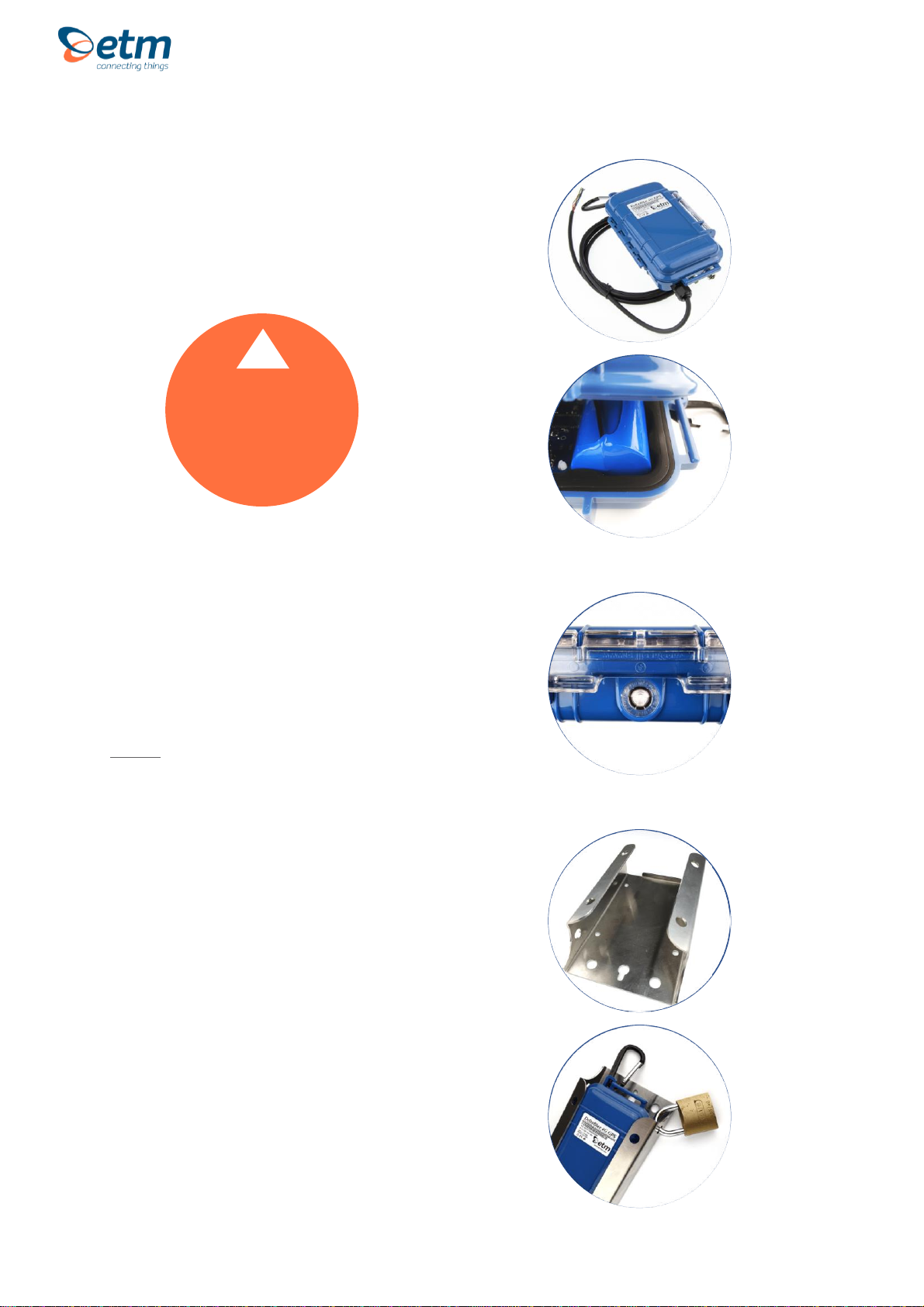
Casing
The ETM DeltaBlue features an IP67-
rated casing made for outdoor use.
Ventilation
DeltaBlue is equipped with a vent that lets
out moisture, while also preventing it from
getting in.
Note! If the DeltaBlue is to be used as a
pressure sensor, the original ventilator
should be replaced with a special one to
make sure the pressure sensor gives
correct data. Please contact ETM to order
this version.
Mounting Plate
There is an option to attach the DeltaBlue
case to a mounting bracket for wall or
pole mount.
Using the mounting bracket you will also
be able to use an external lock for better
security.
Note! It is important that the lock is
attached on the right side (picture) for it to
provide any security.
Case
CAUTION
Make sure that the
rubber is free from
particles such as sand or
gravel when closing the
case lid.
!

For Support Contact: +61 2 9956 7377 or
sales@etmiot.com.au
Battery
DeltaBlue comes with a pre-installed battery. Battery specifications are shown below.
ITEM
DESCRIPTION
BATTERY
Model
ER34615M (High Power Type)
Capacity
14500mAh/52,2Wh
Voltage
3.6V
Type
Non-rechargeable Lithium Chloride Dioxide Battery

For Support Contact: +61 2 9956 7377 or
sales@etmiot.com.au
I/O Connector –ETM DeltaBlue I/O, I/O GPS
6 x I/O’s are available on the provided 2 or 5 meter I/O cable
Pin allocations are as shown below depending on DIP switch settings.
PIN
FUNCTION
INTERNAL SOCKET
CH1
(Brown)
•Digital Input: LL<0.5V, HL>2.5V, Max Input 50VDC
•Digital Output: LL0V, HL3V, 0.1mA
•Pulse Input: LL<0.5V, HL>2.5V, Max Input 50VDC
DIP switch 1 OFF
Internal pull up 1Mohm
DIP switch 1 ON
Internal pull up 33Kohm
CH2
(Blue)
DIP switch 2 OFF
•Digital Input: LL<0.5V, HL>2.5V, Max Input 50VDC
•Digital Output: LL0V, HL3V, 0.1mA
•Analogue Input: 0-2.5VDC, Max Input 50VDC
DIP switch 2 ON
•Analogue Input: 4-20mA, Max Input 50VDC
CH3
(Yellow)
DIP switch 3 OFF
•Digital Input: LL<0.5V, HL>2.5V, Max Input 50VDC
•Digital Output: LL0V, HL3V, 0.1mA
•Analogue Input: 0-2.5VDC, Max Input 50VDC
DIP switch 3 ON
•Analogue Input: 4-20mA, Max Input 50VDC
CH4
(Green)
DIP switch 4 OFF
•Digital Input: LL<0.5V, HL>2.5V, Max Input 50VDC
•Digital Output: LL0V, HL3V, 0.1mA
•Analogue Input: 0-2.5VDC, Max Input 50VDC
DIP switch 4 ON
•Analogue Input: 4-20mA, Max Input 50VDC
CH5
(Red)
DIP switch 5 OFF
•Digital Input: LL<0.5V, HL>2.5V, Max Input 50VDC
•Digital Output: LL0V, HL3V, 0.1mA
•Analogue Input: 0-2.5VDC, Max Input 50VDC
DIP switch 5 ON
•Analogue Input: 4-20mA, Max Input 50VDC
CH6
(Black)
DIP switch 6 OFF
•Analogue Input: 0-5VDC, Max Input 50VDC
DIP switch 6 ON
•Analogue Input: 0-10VDC, Max Input 50VDC
CAUTION
Take care to ensure
that only the correct
connectors are used or
mechanical damage to
the pins may result.
!

For Support Contact: +61 2 9956 7377 or
sales@etmiot.com.au
Feed
(Orange)
•3.6V (battery voltage), 5V & 16V depending on
rotary switch settings, 100mA Max
GND
(Gray)
Ground

For Support Contact: +61 2 9956 7377 or
sales@etmiot.com.au
I2C Sensor –ETM DeltaBlue I/O, I/O GPS
8 x I2C pins are available on the circuit.
Pin allocations are as shown below.
PIN
CONFIGURABLE FUNCTIONS
INTERNAL SOCKET
CH1
(Brown)
•Addr2
CH2
(Blue)
•SDA (Sensor Data)
CH3
(Yellow)
•SCL (Sensor Clock)
CH4
(Green)
•Addr3
CH5
(Red)
Not used
CH6
(Black)
Not used
CH7
(Orange)
•3.6V (battery voltage), 5V & 16V depending on rotary
switch settings, 100mA Max
CH8
(Grey)
•Ground
CAUTION
Take care to ensure
that only the correct
connectors are used or
mechanical damage to
the pins may result.
!

For Support Contact: +61 2 9956 7377 or
sales@etmiot.com.au
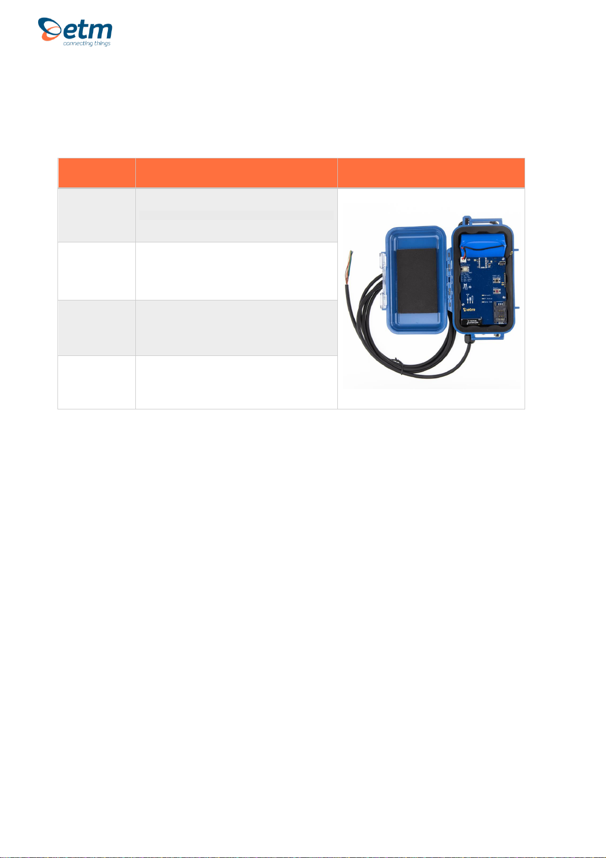
Internal Module
PART #
DESCRIPTION
MODULE
1
Battery connector
2
Sensor feed rotary switch
•Manually adjust the sensor feed. There are three options:
1. 5V Out
2. 16V Out
3. Not used
4. BAT (3.6V battery) out
3
DIP Switch
4
GPS Module
5
Mini USB
•Connects to a computer for configuration and/or firmware
updates
6
Wake-up and send button
•Wakes the module up from hibernation, checks and sends
any data acquired during the hibernation state to ETM IoT
cloud server (EWO)
7
Reset button
•Hardware reset, will reboot the CPU and send start up
package to ETM IoT cloud server (EWO)
8
Signal strength indicators
•Yellow LED’s
9
Status indicators
•Green LED’s
10
Standard SIM-card slot
11
Internal antenna
•Active by default configuration
CAUTION
It's important that the
battery is plugged in
before you connect the
USB Mini
!
For Support Contact: +61 2 9956 7377 or
sales@etmiot.com.au
Internal Sensors
DeltaBlue is equipped with several internal sensors for various applications.
TYPE
SPECIFICATION
Temperature
Accuracy ± 0.2°C
Humidity
Accuracy ± 3 %
Barometric
Pressure
Accuracy ± 0.25% (equivalent to 1m at 400m height
change)
Accelerometer
3-axis motion detector
For Support Contact: +61 2 9956 7377 or
sales@etmiot.com.au
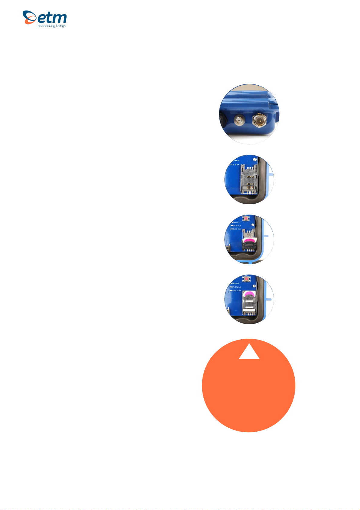
External ports (Only with GPS)
The ETM DeltaBlue GPS terminal
features a standard FME-M antenna
connector (right) as well as a SMA-F GPS
connector (left).
Note! If you intend to use the external
ports, please see (General settings tab)
for setup using the configuration tool.
SIM Card
The SIM card connector is located in the
bottom right corner of the circuit board.
The unit supports both 3V and 1.8V SIMs.
Any SIM card used needs to be correctly
provisioned for the services and network
upon which it is intended to be used.
SIM Pin
If the SIM used has a PIN either:
•The unit can be configured to enter the
SIM pin, refer to the configuration tool
section
OR
•The SIM PIN should be deactivated:
insert the SIM in a mobile phone and
deactivate, then transfer the SIM into the
DeltaBlue unit.
CAUTION
Always disconnect the battery before
inserting or removing
SIM Card.
Care should be taken in inserting
and removing the SIM card so as
not to damage the SIM holder
or cover.
!

For Support Contact: +61 2 9956 7377 or
sales@etmiot.com.au
Indicator LEDs
Green status LEDs
GREEN LED 1
FUNCTION
Slow Flash 500ms On / 500ms Off
Searching for mobile network
Double Flash 3s Off / 100ms ON / 100ms OFF / 100 ms
ON
Active 2G network connection
Triple Flash 3s OFF / 100ms ON / 100ms OFF / 100 ms
ON / 100ms OFF / 100ms ON
Active 3G network connection
Four time Flash 3s OFF / 100ms ON / 100ms OFF / 100
ms ON / 100ms OFF / 100ms ON / 100ms OFF / 100 ms
ON
Active 4G network connection
GREEN LED 2
FUNCTION
ON
Internet Service Provider connection (Active PDP context and IP address)
OFF
No Internet Service Provider connection
GREEN LED 3
FUNCTION
Rapid Flash
Sending Data
ON
Receiving data from host (turn off after 2 seconds)
OFF
No data transmission occurring
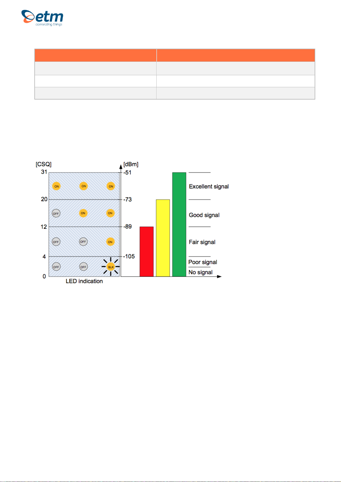
Yellow signal strength LEDs
YELLOW LED 1
FUNCTION
Flashing
RSSI < -105 dBm or no SIM detected
ON
RSSI ≥-105 dBm (Poor signal)
OFF
Not registered to mobile network ≥
YELLOW LED 2
FUNCTION
Flashing
No SIM detected
ON
RSSI ≥-89 dBm (Fair signal)
OFF
RSSI < -89 dBm or Not registered to mobile network
For Support Contact: +61 2 9956 7377 or
sales@etmiot.com.au
YELLOW LED 3
FUNCTION
Flashing
No SIM detected
ON
RSSI ≥-73dBm (Good signal)
OFF
RSSI < -73dBm or Not registered to mobile network
Signal strength levels.

For Support Contact: +61 2 9956 7377 or
sales@etmiot.com.au
CONFIGURATION TOOL
Installation
The Configuration Tool can be copied to any folder on a suitable PC’s hard drive. It consists
of only one file and does not need to be installed. Depending on your use of the tool there
may (over a period of time) be configuration files, with an etx extension, created and these
files can be saved in any location. The tool itself may create a single ini file, which should be
left in the same directory as the configuration tool for continued easy operation of the tool.
Using the Right Version of the Configuration Tool
When the unit starts up and is connected to a terminal window and Escape is pressed (see
below), please check that you have the correct version of the configuration tool. The current
version of the configuration tool is shown in the header (0702 being the relevant part in the
example below), the correct version for the unit is shown in the terminal window.
If you do not have the correct version of the configuration tool, contact ETM and request the
appropriate version or visit ETM’s website.
CAUTION
Do not try to
program/configure a unit
with the wrong version of
the configuration tool.
!

For Support Contact: +61 2 9956 7377 or
sales@etmiot.com.au
Using the Configuration Tool
When you power up the wireless modem to do any configuration you MUST follow these
steps if you are unfamiliar with the operation of the Configuration Tool:
1. Start the configuration tool.
2. Chose the correct communications port (using the Set COM Port button to select a port other
than the one chosen by the Configuration Tool) –ensure the port is set for a baud rate of
115200 (it must be at this speed to be programmed in ESC mode).
3. Confirm that the port opens (the indicator MUST show ‘OPEN’ for your chosen port).
4. Click on the Terminal tab.
5. Click into the terminal window so that you see a flashing cursor.
6. Power up DeltaBlue by connecting the battery to the circuit board.
7. Immediately after powering up the modem press the ESC key on the keyboard, you should
only need to press it 3 or 4 times, after a short period you should see an ‘Escape Pressed’
message from the wireless modem –if you don’t and instead you see a ‘MS:^SYSSTART’
message then repeat the process again. Without the ‘Escape Pressed’ message being
displayed you CANNOT perform any configuration on the wireless modem (while it is possible
to use the Configuration Tool once the wireless modem has fully started up this may not be
possible if the wireless modem has not yet been fully configured).
8. NOTE: You can also check the tick-box ‘Send <ESC> on SYSTEM START’ (the Configuration
Tool to will automatically send an ESC character when it sees the SYSTEM START message)
in the bottom right hand corner of the Configuration Tool (but this doesn’t work with some USB
to Serial adapters) –if you check this remember to uncheck it again when you restart the
modem after any programming changes, otherwise you may inadvertently leave the modem in
programming mode rather than run mode.
9. You are now ready to use the configuration tool to make changes to the wireless modem.
10. Once you are familiar with the Configuration Tool you can shorten the procedure, if the wireless
modem is already live/working, by simply reading and writing the configuration without
restarting the wireless modem and pressing the ESC key. Note if any changes are made to the
modem you should power cycle or software reset (ET&SR) the modem to ensure that any new
mode of operation (based on your configuration changes) comes into effect. If you make no
changes, only reading the configuration, you do not need to restart the modem.
11. Settings can be saved to a file on your PC. If you need to configure another DeltaBlue with the
same settings this file can be loaded into the configuration tool and written to any additional
units that require the same settings.
Details regarding each tab in the configuration tool are provided in the following pages.
The following configuration examples are provided later in the user guide:
•Basic I/O Control
•Temperature Alarm

For Support Contact: +61 2 9956 7377 or
sales@etmiot.com.au
Saving, reading and writing configuration files
•To open an existing configuration file, select "File –Open".
•To save a configuration file, select "File –Save". This can be done after you have read an
existing configuration from the wireless modem, or when you have manually entered a
configuration.
•To read the current settings of the wireless modem, select "READ MEMORY" (the button
with blue text).
•To write the current settings of the configuration tool to the wireless modem, select "WRITE
MEMORY" (the button with red text).
•Note: You cannot perform a write operation if you have not opened an existing configuration
file or performed a read operation.
•The button "Com3 (115200): OPEN" can be used to control whether or not the
communications port is opened (you must have the communications port open to connect in
any way to the modem).
oThe port open/Close feature allows you to leave the configuration tool open but not
connected to the USB Port, in case you need to use another communication
application.
oThe selected baud rate for the Com port is displayed in brackets when the port is
opened.
oTo set which port to use, click the button "Set COM Port".
•Note: If the unit is busy, a read or write may fail and a popup will inform you about the error.
This is usually because the unit is in normal/operational mode. You can retry the read or
write operation, but if it continues to fail then put the unit into programming/ESC mode (see
above).

For Support Contact: +61 2 9956 7377 or
sales@etmiot.com.au
GENERAL SETTINGS TAB
Phone number to SMS Alarm recipients
•Number 1-5 lists the recipients of the alarm messages. It is our recommendation that you
use the full international number in any entry, e.g. +4670xxxxxxx.
Analogue Values
•"Default (presented in mV)" –Analogue values, sent by TCP, UDP or SMS, are presented in
mV. The range of each analogue input is 0-2500 mV.
•"Scaled with calibrated values" –Analogue values, sent by TCP, UDP or SMS, are
presented as calibrated/scaled values. Refer to section on calibration for more details.
Unit ID added to messages
•If you select "Use SIM Card ID as Unit ID" the ID of the unit will be the ID of the SIM.
Other manuals for DeltaBlue
1
This manual suits for next models
4
Table of contents
Other ETM Measuring Instrument manuals


Popular Measuring Instrument manuals by other brands

USA Measurements
USA Measurements US-3011 Operation manual

Bosch
Bosch Professional GLM 400 Series Original instructions

Shodex
Shodex RSpak DE-413 Operation manual

Agilent Technologies
Agilent Technologies PNA Series Installation and quick start guide

Myron L
Myron L RO Meter RO-1 user manual

Rixen
Rixen M-700 user manual


