EUROCOM T890M User manual


Preface
I
Preface
Computer
T890M
Service Manual

Preface
II
Preface
Notice
The company reserves the right to revise this publication or to change its contents without notice. Information contained
herein is for reference only and does not constitute a commitment on the part of the manufacturer or any subsequent ven-
dor. They assume no responsibility or liability for any errors or inaccuracies that may appear in this publication nor are
they in anyway responsible for any loss or damage resulting from the use (or misuse) of this publication.
This publication and any accompanying software may not, in whole or in part, be reproduced, translated, transmitted or
reduced to any machine readable form without prior consent from the vendor, manufacturer or creators of this publica-
tion, except for copies kept by the user for backup purposes.
Brand and product names mentioned in this publication may or may not be copyrights and/or registered trademarks of
their respective companies. They are mentioned for identification purposes only and are not intended as an endorsement
of that product or its manufacturer.
Version 1.0
October 2009
Trademarks
Windows®is a registered trademark of Microsoft Corporation.
Other brand and product names are trademarks and/or registered trademarks of their respective companies.

Preface
III
Preface
About this Manual
This manual is intended for service personnel who have completed sufficient training to undertake the maintenance and
inspection of personal computers.
It is organized to allow you to look up basic information for servicing and/or upgrading components of the T890M series
computer.
The following information is included:
Chapter 1, Introduction, provides general information about the location of system elements and their specifications.
Chapter 2, Disassembly, provides step-by-step instructions for disassembling parts and subsystems and how to upgrade
elements of the system.
Appendix A, Part Lists
Appendix B, Schematic Diagrams

Preface
IV
Preface
IMPORTANT SAFETY INSTRUCTIONS
Follow basic safety precautions, including those listed below, to reduce the risk of fire, electric shock and injury to per-
sons when using any electrical equipment:
1. Do not use this product near water, for example near a bath tub, wash bowl, kitchen sink or laundry tub, in a wet
basement or near a swimming pool.
2. Avoid using a telephone (other than a cordless type) during an electrical storm. There may be a remote risk of elec-
trical shock from lightning.
3. Do not use the telephone to report a gas leak in the vicinity of the leak.
4. Use only the power cord and batteries indicated in this manual. Do not dispose of batteries in a fire. They may
explode. Check with local codes for possible special disposal instructions.
5. This product is intended to be supplied by a Listed Power Unit with an AC Input of 100 - 240V, 50 - 60Hz, DC Output
of 19V, 1.58A or 19V, 1.57A (30 Watts) minimum AC/DC Adapter.
CAUTION
TO REDUCE THE RISK OF FIRE, USE ONLY NO. 26 AWG OR LARGER,
TELECOMMUNICATION LINE CORD

Preface
V
Preface
Instructions for Care and Operation
The computer is quite rugged, but it can be damaged. To prevent this, follow these suggestions:
1. Don’t drop it, or expose it to shock. If the computer falls, the case and the components could be damaged.
• Do not place it on an unstable surface.
• Do not place anything heavy on the computer
2. Keep it dry, and don’t overheat it. Keep the computer and power supply away from any kind of heating element.
This is an electrical appliance. If water or any other liquid gets into it, the computer could be badly damaged.
• Do not expose it to excessive heat.
• Do not leave it in a place where foreign matter or moisture may affect the system.
• Don’t store the computer in a humid environment.
3. Avoid interference. Keep the computer away from high capacity transformers, electric motors, and other strong
magnetic fields. These can hinder proper performance and damage your data.
4. Follow the proper working procedures for the computer. Shut the computer down properly and don’t forget to
save your work. Remember to periodically save your data as data may be lost if the battery is depleted
• Do not turn off the power until you properly shut down all programs.
• Do not turn off any peripheral devices when the computer is on.
• Do not disassemble the computer by yourself.
• Perform routine maintenance on your computer.
5. Take care when using peripheral devices.
• Use only approved brands of peripherals.
• Unplug the power cord before attaching peripheral devices.

Preface
VI
Preface
Power Safety
The computer has specific power requirements:
• Only use a power adapter approved for use with this computer.
• Your AC adapter may be designed for international travel but it still requires a steady, uninterrupted power supply. If you are unsure of
your local power specifications, consult your service representative or local power company.
• The power adapter may have either a 2-prong or a 3-prong grounded plug. The third prong is an important safety feature; do not defeat
its purpose. If you do not have access to a compatible outlet, have a qualified electrician install one.
• When you want to unplug the power cord, be sure to disconnect it by the plug head, not by its wire.
• Make sure the socket and any extension cord(s) you use can support the total current load of all the connected devices.
• Before cleaning the computer, make sure it is disconnected from any external power supplies.
Do not plug in the power
cord if you are wet. Do not use the power cord if
it is broken. Do not place heavy objects
on the power cord.
Power Safety
Warning
Before you undertake
any upgrade proce-
dures, make sure that
you have turned off the
power, and discon-
nected all peripherals
and cables (including
telephone lines). It is
advisable to also re-
move your battery in
order to prevent acci-
dentally turning the
machine on.

Preface
VII
Preface
Battery Precautions
• Only use batteries designed for this computer. The wrong battery type may explode, leak or damage the computer.
• Do not continue to use a battery that has been dropped, or that appears damaged (e.g. bent or twisted) in any way. Even if the
computer continues to work with a damaged battery in place, it may cause circuit damage, which may possibly result in fire.
• Recharge the batteries using the computer’s system. Incorrect recharging may make the battery explode.
• Do not try to repair a battery pack. Refer any battery pack repair or replacement to your service representative or qualified service
personnel.
• Keep children away from, and promptly dispose of a damaged battery. Always dispose of batteries carefully. Batteries may explode
or leak if exposed to fire, or improperly handled or discarded.
• Keep the battery away from metal appliances.
• Affix tape to the battery contacts before disposing of the battery.
• Do not touch the battery contacts with your hands or metal objects.
Battery Guidelines
The following can also apply to any backup batteries you may have.
• If you do not use the battery for an extended period, then remove the battery from the computer for storage.
• Before removing the battery for storage charge it to 60% - 70%.
• Check stored batteries at least every 3 months and charge them to 60% - 70%.
Battery Disposal
The product that you have purchased contains a rechargeable battery. The battery is recyclable. At the end of its useful life, under var-
ious state and local laws, it may be illegal to dispose of this battery into the municipal waste stream. Check with your local solid waste
officials for details in your area for recycling options or proper disposal.
Caution
Danger of explosion if battery is incorrectly replaced. Replace only with the same or equivalent type recommended by the manufacturer.
Discard used battery according to the manufacturer’s instructions.
Battery Level
Click the battery icon in the taskbar to see the current battery level and charge status. A battery that drops below a level of 10%
will not allow the computer to boot up. Make sure that any battery that drops below 10% is recharged within one week.

Preface
VIII
Preface
Related Documents
You may also need to consult the following manual for additional information:
User’s Manual on CD
This describes the computer’s features and the procedures for operating the computer and its ROM-based setup program.
It also describes the installation and operation of the utility programs provided with the computer.

Preface
IX
Preface
Contents
Introduction ..............................................1-1
Overview .........................................................................................1-1
System Specifications .....................................................................1-2
External Locator - LCD Panel View ...............................................1-4
External Locator - Top & Right side Views ...................................1-5
External Locator - Left Side & Bottom View .................................1-6
External Locator - Rear View .........................................................1-7
Mainboard Overview - Top (Key Parts) .........................................1-8
Mainboard Overview - Bottom (Key Parts) ....................................1-9
Mainboard Overview - Top (Connectors) .....................................1-10
Mainboard Overview - Bottom (Connectors) ...............................1-11
Disassembly ...............................................2-1
Overview .........................................................................................2-1
Maintenance Tools ..........................................................................2-2
Connections .....................................................................................2-2
Maintenance Precautions .................................................................2-3
Disassembly Steps ...........................................................................2-4
Removing the Battery ......................................................................2-5
Removing the Hard Disk Drive .......................................................2-6
Removing the System Memory (RAM) ..........................................2-8
Removing the Wireless LAN Module .............................................2-9
Removing the Bluetooth Module ..................................................2-10
Part Lists ..................................................A-1
Part List Illustration Location ........................................................A-2
MB with RFID ...............................................................................A-3
Back Cover .....................................................................................A-4
LCD with Barcode Reader .............................................................A-5
LCD without Barcode Reader ........................................................A-6
Schematic Diagrams.................................B-1
System Block Diagram ...................................................................B-2
Clock Generator ..............................................................................B-3
Silverthorne, Thermal IC 1/2 ..........................................................B-4
Silverthorne 2/2 ..............................................................................B-5
Poulsbo 1/6 Host .............................................................................B-6
Poulsbo 2/6 VGA, LVDS, RTC .....................................................B-7
Poulsbo 3/6 USB, PATA/IDE ........................................................B-8
Poulsbo 4/6 DDR2 ..........................................................................B-9
Poulsbo 5/6 Power ........................................................................B-10
Poulsbo 6/6 VSS ...........................................................................B-11
DDR2 SO-DIMM .........................................................................B-12
CH7317 SDVO to CRT ................................................................B-13
LVDS Conn, LCD Power, CRT ...................................................B-14
SDIO, Mini Card, B/T, CCDI .......................................................B-15
New Card Socket ..........................................................................B-16
JMH 330 SATA ............................................................................B-17
PCI-E LAN RTL8102E ................................................................B-18
Audio Codec ALC269 QFN .........................................................B-19
Touch Panel Control .....................................................................B-20
USB2.0, GSensor, GPS, RFID .....................................................B-21
TO SW, Barcode Conn .................................................................B-22
Hotkey Board ................................................................................B-23
KBC-ITE IT8513E & BIOS .........................................................B-24
VDD5, VDD3 ...............................................................................B-25
System VS Power .........................................................................B-26
VCCNB, 1.5V, 1.05VS, M_BTN .................................................B-27
1.8V, 0.9VS ..................................................................................B-28
VCORE .........................................................................................B-29
AC-In, Charger .............................................................................B-30

Preface
X
Preface
Fingerprint Board .........................................................................B-31
USB Board ...................................................................................B-32

Introduction
Overview 1 - 1
1.Introduction
Chapter 1: Introduction
Overview
This manual covers the information you need to service or upgrade the T890M series computer. Information about op-
erating the computer (e.g. getting started, and the Setup utility) is in the User’s Manual. Information about drivers (e.g.
VGA & audio) is also found in User’s Manual. That manual is shipped with the computer.
Operating systems (e.g. Windows XP, Windows Vista, etc.) have their own manuals as do application software (e.g. word
processing and database programs). If you have questions about those programs, you should consult those manuals.
The T890M series is designed to be upgradeable. See Disassembly on page 2 - 1 for a detailed description of the upgrade
procedures for each specific component. Please note the warning and safety information indicated by the “” symbol.
The balance of this chapter reviews the computer’s technical specifications and features.

Introduction
1 - 2 System Specifications
1.Introduction
System Specifications
Processor Options
Intel® Atom Processor:
512K On-die L2 Cache, 533MHz FSB, FC-
BGA8 Package
Z520 (1.33GHz), Z530 (1.60GHz), Z540
(1.86GHz)
Core Logic
Intel® US15W Chipset
LCD Options
8.9” WSVGA (1024 * 600) TFT LED Backlight
LCD with Touch Panel (Stylus Pen & Finger
Sensitivity) - Factory Option
8.9” WSVGA (1024 * 600) TFT LED Backlight
LCD with Touch Panel (Stylus Pen & Finger
Sensitivity) -
(Sunlight Readable with Brightness at least
350 nits) - Factory Option
Memory
One 200 Pin SO-DIMM Socket Supporting
DDRII (DDR2) 553MHz
Memory Expandable up to 2GB
Video Adapter
Intel® US15W Integrated Video
(Intel® Graphics Media Accelerator 500)
Video Camera
2M Pixel Video Camera Module with USB
Interface
BIOS
One 8Mb SPI Flash ROM
Phoenix™ BIOS
Drop Protection
G-Sensor SoftwareHDD Drop Protection from
40cm when system is powered on
Shock Mounted HDD Drop protection from
120cm when system is powered off
Storage
Shock Mounted Hard Disk Drive
SATA 2.5" HDD or SATA Solid State Drive
(Factory option) Single Level Cell
Audio
Intel® High Definition Audio
Built-In Microphone
2 * Built-In Speakers (1.5W)
Button Keys
5 Directional Key Buttons (Camera, Zoom,
Page Up, Page Down & Menu)
Interface
Two USB 2.0 Ports
One External Monitor Port
One Headphone-Out Jack
One Microphone-In Jack
One RJ-45 LAN Jack
One Docking Connector
One DC-In Jack
Card Reader/ExpressCard
Intel® US15W Integrated 5-in-1 Card Reader
(SD/ Mini SD/ SDIO/ MMC/ RS MMC) Note:
Mini SD/ SDIO/ RS MMC Cards require a PC
adapter
One ExpressCard 34 Slot
Communication
Built-In 10M/100Mb Base-TX Ethernet LAN
Bluetooth 2.1 + EDR (Enhanced Data Rate)
Module
802.11b/g Wireless LAN Mini-Card Module
with USB interface
GPS Module (Factory Option)
HF RFID Reader (Factory Option)
Security
Security (Kensington® Type) Lock Slot
Fingerprint ID Reader Module
BIOS Password
Power Management
Supports Wake on LAN
Power
Full Range AC/DC Adapter
AC input 100 - 240V, 50 - 60Hz,
DC Output 19V, 1.58A or 19V, 1.57A (30
Watts)
Li-Polymer 6600mAH Battery Pack
Energy Star 5.0
Hot Swap Design
Battery Gauge Indicator
Battery Life Around 10 Hours

Introduction
System Specifications 1 - 3
1.Introduction
Operating System
Windows® Vista Home Basic 32bit (with
Service Pack 2)
Windows® XP (with Service Pack 3)
Environmental Spec
Temperature
Operating: 5°C - 35°C
Non-Operating: -20°C - 60°C
Relative Humidity
Operating: 20% - 80%
Non-Operating: 10% - 90%
Dimensions & Weight
239mm (w) * 190mm (d) * 30mm (h)
Around 1.5 kg With Battery
Indicators
Power/ Suspend/ Battery/ HDD
Battery Gauge
Optional
USB to RS232 Cable
Docking Station (Power Charge and USB * 4)
Input 12V-24Vdc, Output 19V Car Adapter,
60W
Shoulder Strap/Carrying Handle/Hand Holder
Charger Box
One External 12.7 mm Combo/Super Multi
USB Optical Device Drive
Factory Options
GPS Module
Bluetooth 2.1 + EDR (Enhanced Data Rate)
Module
HF RFID Reader
8.9” WSVGA (1024 * 600) TFT LED Backlight
LCD with Touch Panel (Stylus Pen & Finger
Sensitivity)
8.9” WSVGA (1024 * 600) TFT LED Backlight
LCD with Touch Panel (Stylus Pen & Finger
Sensitivity) -
(Sunlight Readable with Brightness at least
350 nits)
Introduction
1 - 4 External Locator - LCD Panel View
1.Introduction
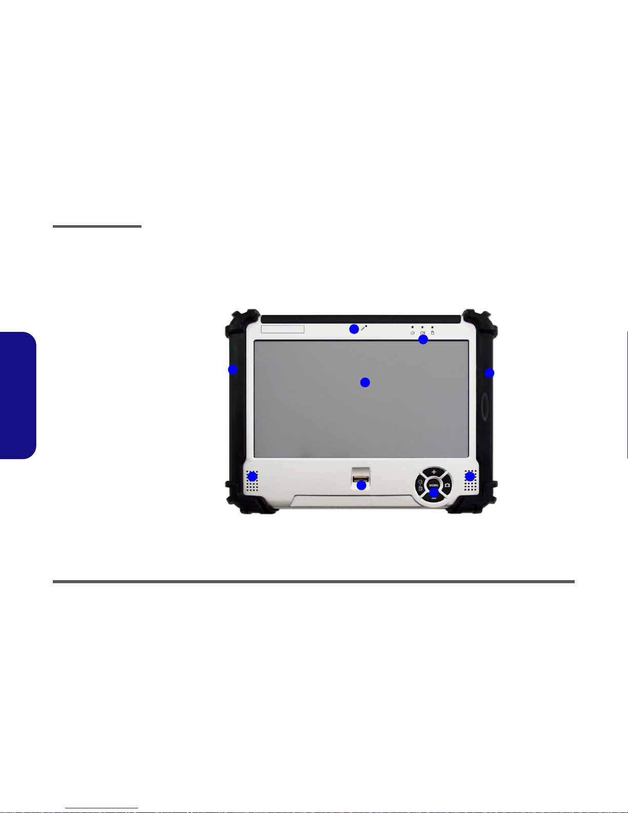
External Locator - LCD Panel View
Figure 1
LCD Panel View
1. Built-In
Microphone
2. LED Indicators
3. LCD Touch Panel
Screen
4. Speakers
5. Fingerprint
Reader
6. 5 Function
Buttons
7. Protective
Surround
2
1
7
4
6
3
54
7

Introduction
External Locator - Top & Right side Views 1 - 5
1.Introduction
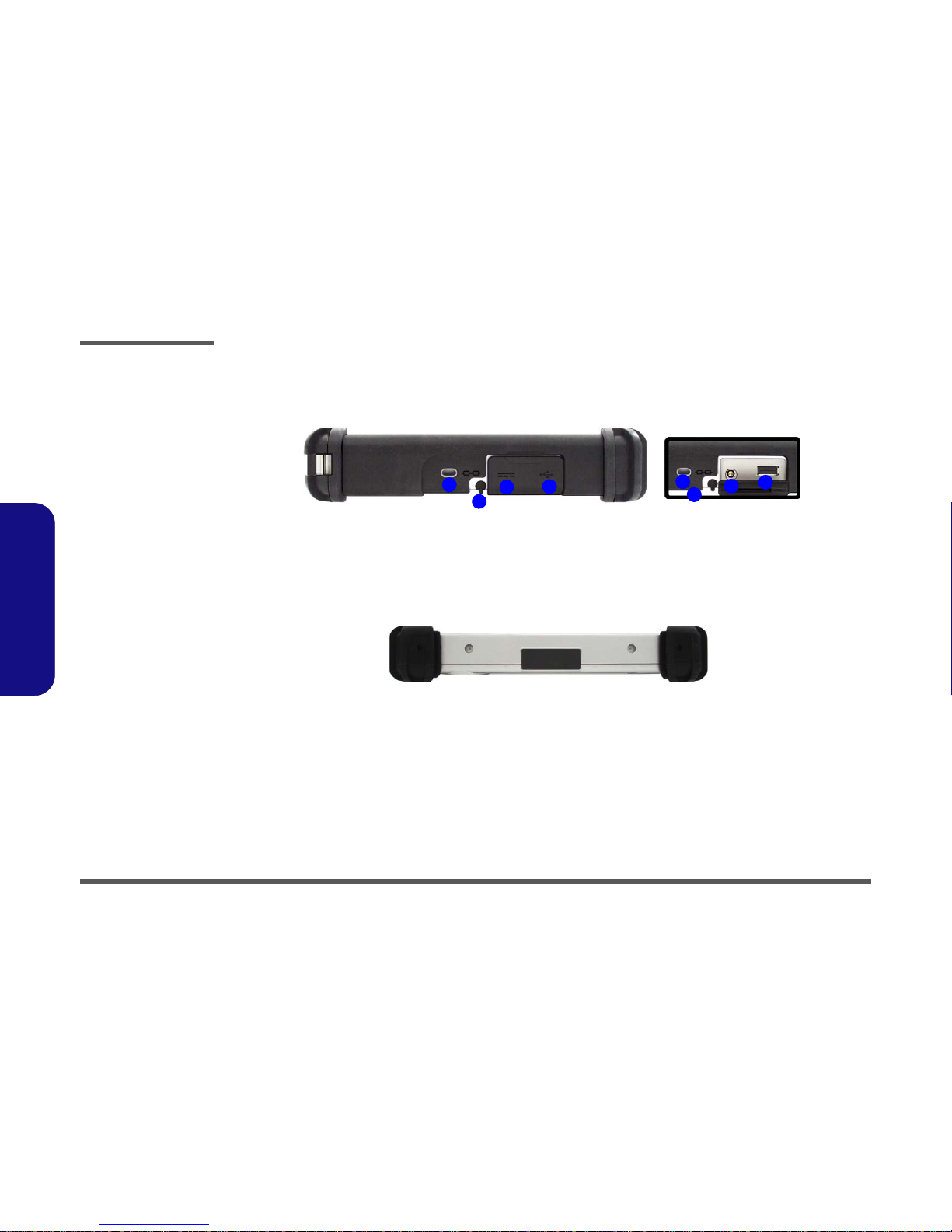
External Locator - Top & Right side Views
Figure 2
Front Views
1. Strap Holders (for
Carrying Strap)
2. Power Button
3. RFID (Radio
Frequency
Identification)
Reader (Factory
Option)
4. RJ-45 LAN Jack
5. 1 * USB 2.0 Ports
Figure 3
Right Side Views
1. Headphone-Out
Jack
2. External Monitor
Port
3. Card Reader
Cover
4. ExpressCard 34
Slot (see below)
5. 5-in-1 Card
Reader
2 3 5
4
1 1
25
4
1 3 12
Introduction
1 - 6 External Locator - Left Side & Bottom View
1.Introduction
External Locator - Left Side & Bottom View
Figure 4
Left Side View
1. Security Lock Slot
2. Stylus Pen &
Holder
3. DC-In Jack
4. 1 * USB 2.0 Port
24
134
3
12
Figure 5
Bottom View

Introduction
External Locator - Rear View 1 - 7
1.Introduction
External Locator - Rear View
Figure 6
Rear View
1. Built-InPCCamera
2. GPS Active Aerial
Socket (for
optional Active
Aerial)
3. Protective
Surround
4. Stylus Pen &
Holder
5. Battery Gauge
6. Battery
Overheating
To prevent your com-
puter from overheating
make sure nothing
blocks the vent/fan in-
takes while the com-
puter is in use.
1
3
6
5
3
4
2
Introduction
1 - 8 Mainboard Overview - Top (Key Parts)
1.Introduction
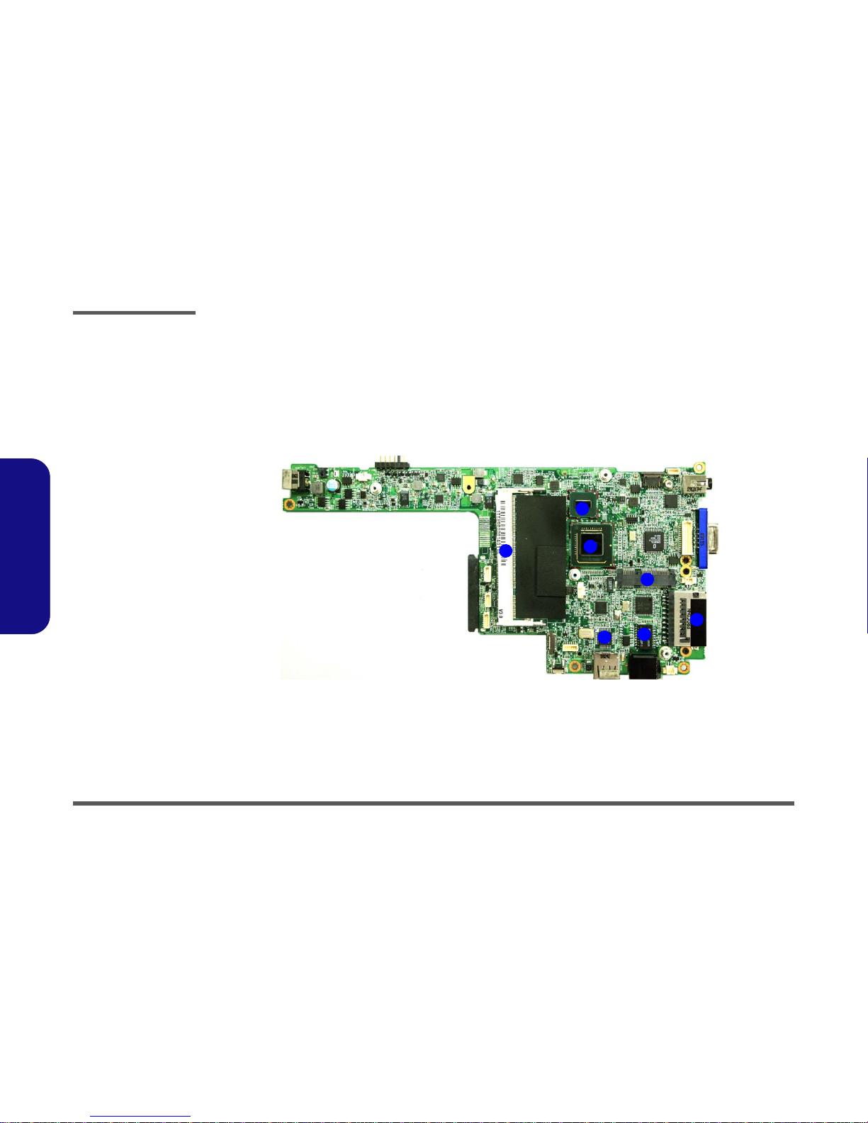
Mainboard Overview - Top (Key Parts)
Figure 7
Mainboard Top
Key Parts
1. Intel Atom CPU
2. Memory Slots
DDR2 SO-DIMM
3. SystemController
Hub
4. Super I/O
5. Transformer
6. Card Reader
Socket
7. Mini-Card
Connector
(WLAN Module)
1
3
4
2
56
7
Table of contents
Other EUROCOM Desktop manuals

EUROCOM
EUROCOM LCD PC User manual

EUROCOM
EUROCOM LP200SC User manual

EUROCOM
EUROCOM LP200ST User manual

EUROCOM
EUROCOM LCD PC User manual

EUROCOM
EUROCOM L295P B User manual

EUROCOM
EUROCOM LP285PB User manual

EUROCOM
EUROCOM LP295 User manual

EUROCOM
EUROCOM LP-297PB User manual

EUROCOM
EUROCOM Multimedia PC V12.1.00 User manual

EUROCOM
EUROCOM L295U Series User manual


