manuals.online logo
Brands
  1. Home
  2. •
  3. Brands
  4. •
  5. Bosch
  6. •
  7. Accessories
  8. •
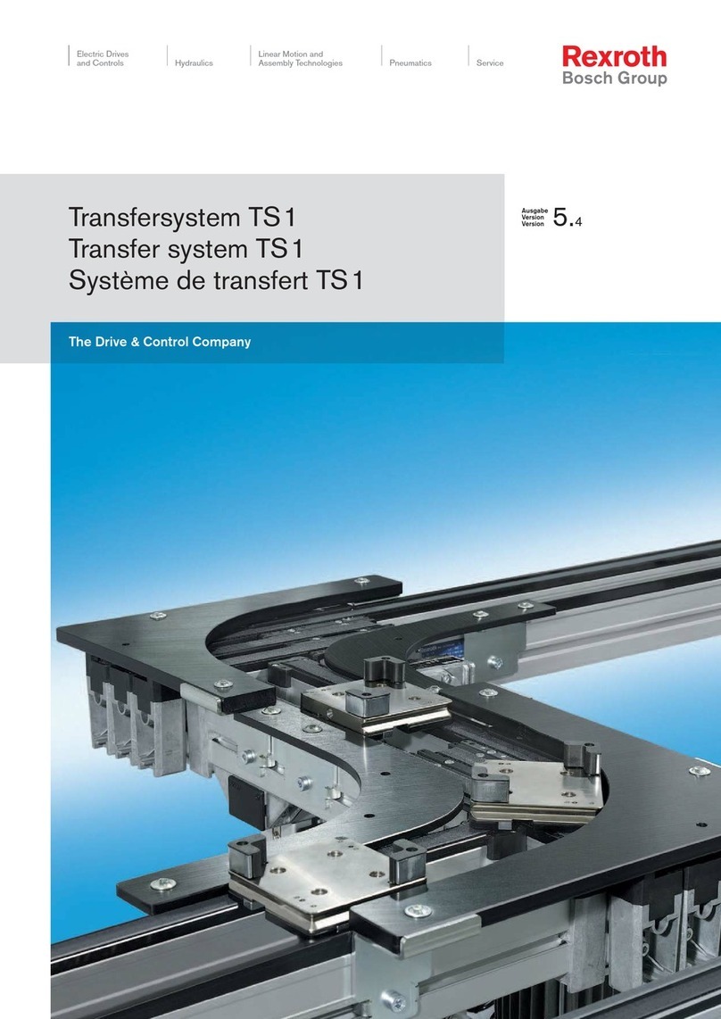
  9. Bosch REXROTH BS 1 User manual

Bosch REXROTH BS 1 User manual

The Drive & Control Company DE
EN
FR
IT
ES
PT
3 842 522 488 (2003.09)
DE+EN+FR+IT+ES+PT
Bandstrecke BS 1
Transverse conveyor BS 1
Section à bande BS 1
Tratto a nastro BS 1
Tramo de cinta BS 1
Via de esteira BS 1
3 842 999 898
TS 123 842522 488 (2003.09)Bosch Rexroth AG
Sicherheitshinweise!
Safety instructions!
Conseils de sécurité

Die Installation, Inbetriebnahme, Wartung
und Instandsetzung, darf nur unter
Berücksichtigung aller
Sicherheitshinweise und -Vorschriften
und nur durch geschultes,
eingewiesenes Fachpersonal
durchgeführt werden!
Alle Sicherheitsabdeckungen, die bei
Wartungsarbeiten entfernt wurden,
müssen vor der Inbetriebnahme wieder
angebracht werden!
Elektrische Anschlüsse nach der
entsprechenden nationalen Vorschrift.
Für Deutschland: VDE-Vorschrift
VDE 0100!
Vor allen Instandsetzungs-, und
Wartungsarbeiten sind die
Energiezuführungen (Hauptschalter,
Druckminderventil etc.) abzuschalten!
Außerdem sind Massnahmen
erforderlich, um ein unbeabsichtigtes
Wiedereinschalten zu verhindern, z. B.
am Hauptschalter ein entsprechendes
Warnschild "Wartungsarbeiten",
"Instandsetzungsarbeiten" etc.
anbringen!
Die bestimmungsgemäße Verwendung
der BS 1 ist der Werkstücktransport auf
Rexroth-Werkstückträgern WT 1 im
Rexroth-Transfersystem TS 1.
Die BS 1 ist nicht begehbar!
Haftung:
Bei Schäden, die aus nicht
bestimmungsgemäßer Verwendung und
aus eigenmächtigen, in dieser Anleitung
nicht vorgesehenen Eingriffen entstehen,
erlischt jeglicher Gewährleistungs- und
Haftungsanspruch gegenüber dem
Hersteller.
Gewährleistung:
Bei Nichtverwendung von
Originalersatzteilen erlischt der
Gewährleistungsanspruch!
Ersatzteilliste MTparts.:
3 842 529 770.
Umweltschutz:
Beim Austausch von Schadteilen ist auf
eine sachgerechte Entsorgung achten!

Installation, initial operation, maintenance
and repair work may only be carried out
in accordance with the relevant safety
instructions and regulations and only by
qualified and specially trained personnel!
All security coverings that have been
removed during repair works have to be
reinstalled before comissioning!
All electrical connections must be made
in accordance with the applicable
national regulations. For Germany:
regulation VDE 0100 (VDE, German
Association of Electricians)!
The current must always be switched off
(at main switch, pressure relief valve etc.)
before maintenance and repair work!
Take precautions to prevent inadvertent
restoration of power, e.g. by hanging a
suitable warning sign at the main switch,
such as:
"Maintenance work in progress", or
"Repair work in progress"!
The BS 1 is only designed for the
transport of workpiece pallets in the
TS 1 transfer system with
Rexroth WT 1 workpiece pallets.
Walking on the BS 1 is not permitted!
Liability:
In no event can the manufacturer accept
claims for warranty or liability arising from
damages caused by improper use, or
intervention in the appliance other than
that described in this instruction manual.
Warranty:
The manufacturer can accept no claims
for warranty arising from the use of non-
original spare parts!
Spare parts list MTparts.:
3 842 529 770.
Environmental protection:
Always properly dispose of damaged
parts once replacement work is
complete!

L'installation, la mise en service, la
maintenance et les réparations ne
peuvent être effectuées que par des
personnes agréées et compétentes et
en respectant les conseils de sécurité!
Avant la mise en service, remettre en
place tous les carters de sûreté enlevés
pour les travaux de maintenance !
Les branchements électriques doivent
être conformes à la réglementation
nationale. Pour l'Allemagne : norme VDE
0100 !
Avant d'effectuer des réparations ou des
travaux de maintenance, couper
l'alimentation en énergie (interrupteur
principal, mano-détendeur etc.) !
D'autre part, prendre toutes les mesures
nécessaires pour éviter une remise en
marche accidentelle, en apposant par
exemple près de l'interrupteur principal
un panneau d'avertissement "travaux de
maintenance", "réparations" etc. !
Le convoyeur transversal électrique BS 1
n'a été conçu que pour le transport de
pièces dans le système de transfert TS 1
avec les palettes porte-pièces WT 1 de
Rexroth.
Il est interdit de monter sur le BS 1 !
Responsabilité :
Le fabricant décline toute responsabilité
et exclut toute réclamation concernant
les dommages dus à une utilisation non
conforme ou suite à des modifications
effectuées sans autorisation et non
prévues ci-contre.
Garantie :
En cas de non-utilisation des pièces
détachées d'origine, le constructeur
exclut toute responsabilité !
Liste de pièces de rechange MTparts.:
3 842 529 770.
Protection de l'environnement :
Veiller à ce que les pièces endommagées
soient éliminées en toute conformité !
TS 1 3Bosch Rexroth AG3 842522 488 (2003.09)
DE
EN
FR
IT
ES
PT
Fig. 1
”A”
1
2
4x
M5x16
A5,3-FST
Anlieferungszustand/Lieferumfang B S 1/T
Delivery condition/Scope of delivery
Etat à la livraison/Fournitures

Fig. 1:
1 BS 1, montagefertig mit
Transportsicherung "A"!
2 Getriebemotor mit
Befestigungsmaterial beigelegt.

Fig. 1:
1 BS 1, prêt au montage avec sûreté
"A" !
2 Moto-réducteur et matériel de
fixation inclus.

Fig. 1:
1 BS 1, ready to install with transport
retainer "A"!
2 Gear motor with fastening material
included.
TS 143 842522 488 (2003.09)Bosch Rexroth AG
M6
M6x12
3 842 523 431
4x
Fig. 2
Fig. 3
SZ 1
Fig. 4
3 842 522 764
bWT [mm] Nr./No./N°
80 3 842 528 493 1x
120 3 842 528 494 1x
160 3 842 528 495 1x

Übertrieb-Anbausatz, Fig. 2:
Für den Antrieb einer HQ 1/O
(separate Montageanleitung:
3 842 522 764, ist beigepackt)
Stützen SZ 1, Fig. 3:
Auswahl und Bestell-Nr. siehe TS 1-
Katalog.
Befestigungssatz Fig. 4:
Für den Einbau der BS 1 zwischen
Strecken ST 1.

Kit de montage de la transmission
Fig. 2 :
Pour l’entraînement d’une HQ 1/O
(Instructions de montage à part :
3 842 522 764, ci-jointes)
Colonnes support SZ 1 Fig. 3 :
Assortiment et numéros de référence,
consulter le catalogue TS 1.
Kit de fixation Fig. 4 :
Pour le montage de la BS 1 entre des
sections ST 1.

Connecting shaft mounting kit, Fig. 2:
For driving a HQ 1/O
(separate assembly instructions:
3 842 522 764 are enclosed)
Leg sets SZ 1 Fig. 3:
For selection and order numbers see TS
1 catalogue.
Fastening sets Fig. 4:
For installation of BS 1 between
conveyor sections ST 1.
Zubehör
Accessories
Accessoires
TS 1 5Bosch Rexroth AG3 842522 488 (2003.09)
DE
EN
FR
IT
ES
PT
Fig. 5
500
b - 44
b + 28
b + 30
b + 2
27
l
109,5
30
75
ca. 295
Hauptabmessungen/Funktionsmaße
Main dimensions/Functional dimensions
Dimensions principales/Dimensions fonctionnelles
Motoranbau innen (Fig. 5)
Motor mounting, inner (Fig. 5)
Montage intérieur du moteur (Fig. 5)
TS 163 842522 488 (2003.09)Bosch Rexroth AG
Fig. 6
500
180
b - 44
b + 28
b + 30
b + 2
115
27
l
109,5
30
75
ca. 295
Motoranbau außen (Fig. 6)
Motor mounting, outer (Fig. 6)
Montage extérieur du moteur (Fig. 6)
TS 1 7Bosch Rexroth AG3 842522 488 (2003.09)
DE
EN
FR
IT
ES
PT
Fig. 7
Fig. 8
A
B
C
”A”
2x 2x

Allgemeines:
Das Befestigen der Baueinheit BS 1 im
Transfersystem erfolgt nach dem
Hammerschraubenprinzip.
Dies bewirkt eine kraftschlüssige
Befestigung in den Längsnuten der
Profile. Beim Festschrauben der
Sechskantmutter dreht sich der
Hammerschraubenkopf um 90° in die
richtige Spannposition (Fig. 7),
max. Anzugsdrehmoment 10 Nm.
A = Einsatzlage
B = Klemmlage
C = Anlage in Nut
(Drehmomentstütze)
Transportsicherung "A" erst nach dem
Einbau zwischen ST 1 oder nach der
Montage auf SZ 1 entfernen (Fig. 8)!
Einbau in das Transfersystem
Installing in the transfer system
Montage dans le système de transfert

General:
The BS 1 unit is secured in the transfer
system using the T-bolt principle.
This creates a friction lock in the
longitudinal grooves of the profiles.
When the hex nut is tightened, the
T-bolt head rotates 90° to the proper
fixing position (Fig. 7).
Max. torque 10 Nm.
A = Position on insertion
B = Clamping position
C = Arrangement in groove
(torque support)
Only remove transport retainer "A" after
installation between ST 1 sets or after
mounting on SZ 1 (Fig. 8)!

Généralités :
La fixation du composant BS 1 sur le
système de transfert est assurée suivant
le principe de la vis à tête rectangulaire.
Ceci permet une fixation de force dans
les rainures longitudinales des profilés.
En vissant à fond l'écrou hexagonal, la
tête de la vis à tête rectangulaire pivote
de 90° et se met dans la position de
serrage correcte (Fig. 7),
couple de serrage max. 10 Nm.
A = Position d'insertion
B = Position de serrage
C = Position dans la rainure
(support du couple)
Enlever la sûreté de transport "A"
seulement après avoir monté la section à
bande entre les ST 1 ou sur le SZ 1
(Fig. 8) !
“A“ = Transportsicherung
“A“ = Transport retainer
“A“ = Sûreté de transport
TS 183 842522 488 (2003.09)Bosch Rexroth AG
Fig. 9
SW 8
(4x)
”X”
1
M6
M6x12
3 842 523 431
4x
2
SW 6
10 Nm
SW 6
10 Nm
2

Montagefolge Fig. 9:
1 Gelbe Schutzkappe “X“ von
Motorwelle abziehen, Motor mit
Befestigungssatz am
Getriebeflansch anschrauben, Nabe
im Getriebe ist werkseitig gefettet.
2 Befestigungssätze (3 842 523 431)
an BS 1 montieren.
Fortsetzung Seite 9!

Procédure de montage Fig. 9 :
1 Enlever le capuchon jaune de
protection “X“ de l’arbre du moteur,
visser le moteur à l’aide du kit de
fixation sur la bride du réducteur,
le moyeu du réducteur est lubrifié
en usine.
2 Monter les kits de fixation
(3 842 523 431) sur la BS 1.
Suite page 9 !

Sequence of assembly Fig. 9:
1 Remove yellow protective cap “X“
from motor shaft, mount motor with
fastening set to gear flange, hub in
gear has already been greased in
the factory.
2 Mount fastening sets
(3 842 523 431) to BS 1.
Continued on page 9!
Einbau zwischen Strecken ST 1
Installation between conveyor sections ST 1
Montage entre les sections ST 1
TS 1 9Bosch Rexroth AG3 842522 488 (2003.09)
DE
EN
FR
IT
ES
PT
Fig. 10
SZ 1
ST 1
SZ 1
ST 1
BS 1
l*)
3
SW 6
10 Nm SW 6
10 Nm
3

3 BS 1 von unten zwischen beide
ST 1 einheben und in den T-Nuten
befestigen (Fig. 10)
Der Einbau der BS 1 in die Strecke ST 1
muß aus Gründen der
Funktionssicherheit und zur Verhinderung
des vorzeitigen Verschleißes nach Flucht
und Waage, rechtwinklig und
achsparallel durchgeführt werden!

3 Soulever la BS 1 par en-dessous
entre les deux ST 1 et la fixer dans
les rainures en T (Fig. 10)
Pour des raisons de sécurité de
fonctionnement et pour éviter toute
usure anticipée, lors du montage de la
BS 1 sur une section ST 1, veiller à ce
que celle-ci soit alignée à la verticale
et à l'horizontale en angle droit
parallèlement à l'axe !

3 Lift BS 1 between the two ST 1
sets from underneath and secure
it in the T-grooves (Fig. 10)
The BS 1 must be installed in the
conveyor section ST 1 aligned and
level, at right angles and parallel to the
axis, for reasons of functional safety and
to prevent premature wear!
Einbau zwischen Strecken ST 1
Installation between conveyor sections ST 1
Montage entre les sections ST 1
*) Bei l ≥3000 ist mittig eine Stütze SZ 1 vorzusehen!
*) When l ≥3000 a leg set SZ 1 must be installed mid-length!
*) Lorsque l ≥3000, prévoir un support SZ 1 au milieu!
TS 110 3 842522 488 (2003.09)Bosch Rexroth AG
Fig. 11
1
SW 8
(4x)
”X”

Montagefolge Fig. 11:
1 Gelbe Schutzkappe “X“ von
Motorwelle abziehen, Motor mit
Befestigungssatz am
Getriebeflansch anschrauben. Nabe
im Getriebe ist werkseitig gefettet.
Fortsetzung Seite 11!

Procédure de montage Fig. 11 :
1 Enlever le capuchon jaune de
protection “X“ de l’arbre du moteur,
visser le moteur avec le kit de fixation
sur la bride du réducteur. Le moyeu
du réducteur est lubrifié en usine !
Suite page 11 !

Sequence of assembly Fig. 11:
1 Remove yellow protective cap “X“
from motor shaft, mount motor to
gear flange using fastening set.
Hub in gear has already been
greased in the factory
Continued on page 11!
Montage auf Stützen SZ 1
Mounting on leg sets SZ 1
Montage sur supports SZ 1
TS 1 11Bosch Rexroth AG3 842522 488 (2003.09)
DE
EN
FR
IT
ES
PT
SW 5
10 Nm
SW 5
10 Nm
2
BS 1
SZ 1
SZ 1
SZ 1
2
SW<=2000
Fig. 12

2 BS 1 auf SZ 1 montieren.
Die Bandstecke BS 1 kann je nach
Bestellänge auf zwei bis vier Stützen SZ
1 montiert werden. Die SZ 1 werden
jeweils unter die Querverbinder montiert.
Montagebeispiel Fig. 12:
Streckenlänge l = 4000 mit drei Stützen
SZ1.

2 Monter la BS 1 sur la SZ 1.
La section à bande BS 1, suivant
la longueur commandée, peut être
montée sur 2 à 4 supports SZ 1. Les SZ
1 sont montés sous les liaisons
transversales respectives.
Exemple de montage Fig. 12 :
longueur de section. l = 4000 avec trois
supports SZ 1.

2 Mount BS 1 on SZ 1.
Transverse conveyor BS 1 can be
mounted on between two and four leg
sets SZ 1, depending on the length
ordered. Each SZ 1 is attached under a
cross-connector.
Example of assembly, Fig. 12:
section length l = 4000 with three leg
sets SZ 1.
Montage auf Stützen SZ 1
Mounting on leg sets SZ 1
Montage sur supports SZ 1
TS 112 3 842522 488 (2003.09)Bosch Rexroth AG
Fig. 13
SW 19
SW 13
BS 1
SZ 1
SZ 1
SZ 1
”A”
Ausrichten
Alignment
Alignement

Aligner longitudinalement et
transversalement, pour cela, régler les vis
sans fin des pieds articulés.
Après l'alignement, bloquer avec
l'écrou hexagonal "A" (Fig. 13).

Längs und quer ausrichten, dazu
Spindeln der Gelenkfüße entsprechend
einstellen.
Nach dem Ausrichten mit
Sechskantmutter "A" kontern (Fig. 13).

Align lengthways and widthways,
adjusting the spindles on the hinged feet.
After aligning, counter with hex nut "A"
(Fig. 13).
TS 1 13Bosch Rexroth AG3 842522 488 (2003.09)
DE
EN
FR
IT
ES
PT
Fig. 14
M
D
= 25 Nm
SW13
73
8
3 842 345 081
3 842 528 718
3 842 146 815
3 842 526 560
BS 1
SZ 1
SZ 1
SZ 1
Montage Fundamentwinkelsatz/Bodendübel (Fig. 14)
Mounting foundation set/floor anchor (Fig. 14)
Montage jeu d'équerres de fondation/chevilles de fond (Fig. 14)
TS 114 3 842522 488 (2003.09)Bosch Rexroth AG
Installation/Inbetriebnahme
Installation/Initial operation
Installation/Mise en service
Motoranschluss
Der Motoranschluss ist nach den
Angaben des Typschildes (Fig. A)
entsprechend der Netzspannung nach
Fig. B (Y) oder Fig. C (∆) durchzuführen.
Der Motor ist mit einem Bimetall-Schalter
(potenzialfreier Thermokontakt, 230 V
AC, 300 mA) zur Temperaturüber-
wachung ausgerüstet.
Der Motor ist so anzuschließen, dass bei
Ansprechen des Schalters der Motor
stromlos geschaltet wird.
Anschlusspläne nach Fig. B bzw. Fig. C
sowie Anschlussplan im Klemmenkasten
beachten !
Kabeleinführung so wählen, dass das
Kabel im Betrieb nicht beschädigt
werden kann.
Option Anschlussleitung:
3 842 409 645 (M20x1,5) (Fig. D).
Vorsicherung beachten!
Raccordement du moteur
Procéder au raccordement du moteur
conformément aux spécifications sur la
tension et le courant selon Fig. B (Y) ou
Fig. C (∆) indiquées sur la plaque
signalétique (Fig. A).
Le moteur est équipé pour le contrôle de
la température d’un interrupteur
bimétallique (contact thermique sans
potentiel, 230 V AC, 300 mA). Le
moteur doit être raccordé de telle sorte
que lors du déclenchement de
l’interrupteur, le moteur soit commuté
hors tension.
Tenir compte des schémas de
raccordement selon Fig. B ou Fig. C
ainsi que du schéma de raccordement
dans la boîte de connexions !
Choisir l’entrée de câble de telle sorte
que le câble ne puisse pas être
endommagé pendant le fonctionnement.
Câble de raccordement en option :
3 842 409 645 (M20x1,5) (Fig. D).
Attention au préfusible !
Motor connection
The motor must be connected in
accordance with the voltage and current
information as in Fig. B (Y) or Fig. C (∆)
that is listed on the name plate (Fig. A).
The motor is equipped with a bi-metal
switch (potential-free thermal contact,
230 V AC, 300 mA) to monitor the
temperature.
The motor must be connected in such a
manner that it is currentless when the
switch is actuated.
Observe the connection plans in Fig. B
and Fig. C, as well as the connection
plan in the terminal box!
Select a cable entry that prevents
damage to the cable during operation.
Connection cable option:
3 842 409 645 (M20x1.5) (Fig. D).
Pay attention to ballast fuse!

Für das Transfersystem ist kundenseitig
eine NOT-AUS Einrichtung vorzusehen!
Unfallverhütungsvorschrift
Berufsgenossenschaft Stetigförderer,
VBG 10.
Der Motoranschluss muss durch
Fachpersonal ausgeführt werden!
VDE-Vorschrift VDE 0100 für
Deutschland, bzw die entsprechenden
Vorschriften des Anwenderlandes.
Die Oberflächen von Motoren und
Getrieben können unter bestimmten
Last- und Betriebsbedingungen
Temperaturen von bis zu 70 °C
annehmen. In diesen Fällen müssen durch
entsprechende konstruktive Maßnahmen
(Schutzvorrichtungen) oder
entsprechende Warnzeichen,
die jeweils geltenden Unfallverhütungs-
vorschriften (UVV) erfüllt werden!

Un dispositif d’ARRET D’URGENCE
doit être prévu par le client pour le
système de transfert !
Unfallverhütungsvorschrift
Berufsgenossenschaft Stetigförderer,
VBG 10. (Directives nationales
allemandes de prévention des accidents,
convoyeurs à fonctionnement continu,
VBG 10).
Le raccordement du moteur doit être
effectué par un personnel compétent !
Norme VDE 0100 pour l’Allemagne ou les
réglementations correspondantes du
pays de l’utilisateur.
Dans des conditions de charges et des
conditions ambiantes particulières, les
surfaces des moteurs et engrenages
peuvent atteindre des températures
jusqu’à 70 °C. Dans ces cas, les
directives de prévention d’accident
(UVV) en vigueur doivent être satisfaites
par des mesures constructives
appropriées (dispositifs de protection)
ou des panneaux d’avertissement
appropriés !

The customer is obliged to equip the
transfer system with an EMERGENCY
OFF device.
Unfallverhütungsvorschrift
Berufsgenossenschaft Stetigförderer,
VBG 10. (German accident prevention
regulations of the trade cooperative
association continuous conveyors,
VBG 10).
The motor must be connected by
specialists!
Regulation VDE 0100 of German
Association of Electricians (VDE) for
Germany or the appropriate regulations
for the country where the product is
used.
Unter certain load and operating
conditions, the surfaces of the motors
and gears can reach temperatures of up
to 70°C. In such cases, currently valid
accident prevention regulation (in
Germany: UVV) must be met by
corresponding constructive measures
(safety devices) or safety warning signs!
TS 1 15Bosch Rexroth AG3 842522 488 (2003.09)
DE
EN
FR
IT
ES
PT
L=400mm
3 842 409 645 (M20 x 1,5)
W2 V2
U1 V1 W1
U2
TW
1
TW
2
" "
W2 U2 V2
U1 V1 W1
TW1
TW2
"Y"
Fig. B
Fig. C
Fig. D
Fig. A

Erstinbetriebnahme
Das System nur kurz anlaufen lassen
(max. 2 s) und die richtige Drehrichtung
des Motors überprüfen.
Um die Drehrichtung des Motors zu
ändern, zwei beliebige Drähte (L1, L2
oder L3 , Fig. B / Fig. C) tauschen.
Hinweis:
Korrigieren Sie bei Motoren mit
werksseitiger Steckerausführung die
Drehrichtung im Schaltschrank oder an
der Steckerkupplung (buchsenseitig).
Dies vereinfacht den Austausch.

Initial operation
Start the system for a moment (max. 2 s)
and check that the motor is rotating in
the correct direction.
Exchange any two wires (L1, L2 or L3,
Fig. B / Fig. C) to change the motor’s
direction of rotation.
Note:
In motors with a factory-installed plug,
correct the direction of rotation in the
switch cabinet or at the plug coupling
(socket side). This will simplify
exchanges.

Première mise en service
Démarrer le système seulement
brièvement (max. 2 s) et vérifier le sens
de rotation correct du moteur.
Pour modifier le sens de rotation du
moteur, permuter deux fils quelconques
(L1, L2 ou L3 , Fig. B / Fig. C).
Remarque :
Pour les moteurs avec un connecteur
installé en usine, corriger le sens de
rotation dans l’armoire de commande ou
sur le coupleur du connecteur (côté
douille). Cela simplifie l’échange.
Typschild (Beispiel)
Name plate (example)
Plaque signalétique (exemple)
kein Netzanschluss
No network connection
Pas de raccordement
au réseau
TS 116 3 842522 488 (2003.09)Bosch Rexroth AG

Déconnecter l'alimentation en énergie
(interrupteur principal etc.) avant
d'entreprendre les travaux de
maintenance !
En outre, prendre les mesures
nécessaires pour éviter une remise en
marche accidentelle, placer p. ex. un
panneau d'avertissement près de
l'interrupteur principal !
Tous les paliers sont pourvus d’un
graissage à vie et sont, sous
applications normales, exempt
d’entretien dans la mesure où rien
d’autre n’est indiqué.
Lors de l’utilisation de substances
dissolvant les graisses sur le système,
par ex. pour des buts de nettoyage, un
contrôle régulier est toutefois nécessaire
et, le cas échéant, un regraissage
uniquement avec un lubrifiant sans acide
et exempt de résine (par ex. « gleitmo
585K ») doit être réalisé !
Réducteur (1, Fig. 19)
Le réducteur ne demande pas d'entretien
!
Moteur (2, Fig. 19)
Pour garantir un refroidissement
suffisant, il est indispensable de nettoyer
régulièrement les saletés et la poussière
qui se sont déposés sur le moteur, dans
les orifices d’aspiration du couvercle du
ventilateur et dans les espaces entre les
ailettes de refroidissement en fonction
des conditions ambiantes données.

Prior to maintenance work, disconnect
energy sources (main switch, etc.)!
In addition, take precautions to prevent
inadvertent restoration of power, e. g.,
place a warning sign at the main switch!
All bearings are provided with lifelong
lubrication and are maintenance free
under normal conditions, if not otherwise
indicated.
However, if grease-dissolving
substances are applied to the system,
e.g. for cleaning purposes, a regular
check should be made, and, if necessary,
the bearings should be relubricated with
acid and resin free lubricant only (e.g.
“gleitmo 585K”)!
Gear (1, Fig. 19)
The gear is maintenance-free!
Motor (2, Fig. 19)
To ensure adequate cooling, dirt and
dust must be removed from the motor
surface, the inlets of the fan housing, and
the interior surfaces of the cooling fins
on a regular basis, depending on
environmental and operating conditions.

Vor Wartungsarbeiten sind die
Energiezuführungen (Hauptschalter etc.)
abzuschalten!
Außerdem sind Maßnahmen erforderlich
um unbeabsichtigtes Wiedereinschalten
zu verhindern, z. B. Warnschild am
Hauptschalter anbringen!
Alle Lagerstellen sind mit einer
Lebensdauerschmierung versehen und
unter normalen Anwendungen
wartungsfrei, sofern nicht anders
angegeben.
Beim Einsatz von fettlösenden
Substanzen auf dem System, z.B. für
Reinigungszwecke, ist jedoch eine
regelmäßige Kontrolle und ggf. eine
Nachschmierung nur mit säure- und
harzfreiem Schmierstoff (z.B. „gleitmo
585K“) erforderlich!
Getriebe (1, Fig. 19)
Das Getriebe ist wartungsfrei!
Motor (2, Fig. 19)
Um eine ausreichende Kühlung
sicherzustellen, müssen Schmutz- und
Staubablagerungen an der Oberfläche
des Motors, den Ansaugöffnungen der
Lüfterhaube und an den Zwischenräumen
der Kühlrippen, den Umgebungs- und
Einsatzbedingungen entsprechend,
regelmäßig entfernt werden.
Wartung
Maintenance
Maintenance
TS 1 17Bosch Rexroth AG3 842522 488 (2003.09)
DE
EN
FR
IT
ES
PT
Fig. 19
3
2
1

Températures de surface !
Les surfaces des moteurs et engre-
nages soumises à certaines condi-tions
de charge et de service, peuvent
atteindre des températures supérieures
à 60 degrés Celsius.
Dans ce cas, il est impératif de s'en tenir
aux instructions sur la prévention des
accidents en vigueur en prenant des
mesures adéquates (en installant des
dispositifs de protection) ou en
apposant des panneaux d'avertissement
!
Courroie dentée (3, Fig. 19)
Effectuer des contrôles réguliers en
vérifiant surtout à l'oeil nu si les points de
soudure ne commencent pas à s'user.
Contrôler le sens de marche (dans le
sens de la flèche) !
Graisser le cas échéant la courroie
dentéeavec huile minérale
viscosité68 selon DIN (p. ex. Aral, Shell)

Surface Temperatures!
The surfaces of motors and gears can
reach temperatures of over 60 degrees
Celsius under specific load and
operating conditions.
In such situations the applicable rules for
accident prevention must be fulfilled with
the necessary safety warning signs or
constructive measures (safety devices).
Toothed belt (3, Fig. 19)
Conduct visual inspections regularly for
wear, in particular at the welded joint.
Check transport direction (in direction of
arrow)!
Oil the toothed belt again if necessary
with mineral oil viscosity 68 according to
DIN (e. g. Aral, Shell)

Oberflächentemperaturen!
Die Oberflächen von Motoren und
Getrieben können unter bestimmten
Last-und Betriebsbedingungen
Temperaturen von mehr als 60 Grad
Celsius annehmen.
In diesen Fällen müssen durch
entsprechende konstruktive Maßnahmen
(Schutzvorrichtungen) oder
entsprechende
Sicherheitkennzeichnungswarnzeichen,
die jeweils geltenden
Unfallverhütungsvorschriften (UVV)
erfüllt werden!
Zahnriemen (3, Fig. 19)
Regelmäßige Sichtkontrolle,
insbesondere der Schweißstelle auf
Verschleiß. Laufrichtung (in Pfeilrichtung)
kontrollieren!
Bei Bedarf Zahnriemen nachölen mit:
Mineralöl Viskosität 68 nach DIN (z. B.
Aral, Shell)
TS 118 3 842522 488 (2003.09)Bosch Rexroth AG
Fig. 20
SW 3 1
SW 3
2
3
8
6
7
4
5
4
2x 4
5
Instandsetzung BS 1
Repair BS 1
Réparations BS 1
TS 1 19Bosch Rexroth AG3 842522 488 (2003.09)
DE
EN
FR
IT
ES
PT

Prior to any repair work, disconnect
energy sources (main switch, etc.)!
In addition, take precautions to prevent
inadvertent restoration of power, e.g.,
place a warning sign at the main switch!
If the BS 1 is removed from section ST 1
for maintenance work, a transport
retainer (see Fig. 8) must be attached!
Changing the toothed belt,
motor mounting, inner Fig. 20:
1 Loosen 2 x 4 screws on the drive
side.
2 Lift the entire drive unit upwards,
keeping it level.Do not tilt!
3 Remove the toothed belt sideways.
4 Loosen 2 x 4 screws at the return
end.
5 Lift the entire return unit upwards,
keeping it level.Do not tilt!
6 Remove toothed belt at the side.
7 Remove belt guide profile GP 1.
8 Remove faulty toothed belt.
Install new toothed belt following
instructions in reverse order.
Please note:
For the
direction of movement
of the
toothed belt, the arrow (welded joint)
must point towards the drive unit!
Check that the new toothed belt is oiled
and if necessary, oil it with mineral oil
viscosity 68 according to DIN (e. g. Aral,
Shell)
Installing the drive unit:
Lower steadily into the subframe, taking
care to keep it level and ensure that the
toothed belt sits in the gear teeth of
the toothed belt wheel!
Tighten 2 x 4 fastening screws
alternately and diagonally!

Débrancher l'alimentation en énergie
(interrupteur principal etc.) avant
d'entreprendre tous travaux de
réparation !
En outre, prendre les mesures
nécessaires pour éviter une remise en
marche accidentelle, placer p. ex. un
panneau d'avertissement près de
l'interrupteur principal !
Si, pendant des travaux de maintenance,
la BS 1 est démontée de la section ST
1, mettre une sûreté de transport (voir
Fig. 8) !
Changement de la courroie dentée,
montage intérieur du moteur Fig. 20:
1 Desserrer 2 x 4 vis du côté de
l'entraînement.
2 Ôter l'ensemble de l'unité
d'entraînement en tirant vers le haut
en évitant de le déformer et de
l'accrocher !
3 Enlever la courroie dentée par
le côté.
4 Desserrer 2 x 4 vis sur le côté de
renvoi.
5 Ôter l'ensemble de l'unité de renvoi
en tirant vers le haut en évitant de
le déformer et de l'accrocher !
6 Enlever la courroie dentée par le
côté.
7 Enlever le profilé guide de courroie
GP 1.
8 Enlever la courroie dentée qui est
endommagée.
Pour installer une nouvelle courroie
dentée, suivre les instructions données
ci-dessus dans l'ordre inverse.
Attention:
Sens de la marche
de la courroie
dentée : la flèche (point de soudure) doit
montrer dans la direction de l'unitè
d'entraînement !
Vérifier si la nouvelle courroie dentée a
été graissée, le cas échéant la graisser
avec huile minérale viscosité 68 selon
DIN (p. ex. Aral, Shell)
Pour installer l'unité d'entraînement::
::
: la
mettre bien droite dans la partie
inférieure en veillant à ne pas la coincer
et à ce que la courroie dentée soit bien
mise dans la denture de la roue
dentée !
Serrer 2 x 4 vis de fixation en
alternance
et en "croisé" !

Vor allen Instandsetzungsarbeiten
Energiezuführungen (Hauptschalter etc.)
abschalten! Außerdem sind Maßnahmen
erforderlich, um ein unbeabsichtigtes
Wiedereinschalten zu verhindern, z. B.
Warnschild am Haupt- schalter
anbringen!
Wird die BS 1 zu den
Instandsetzungsarbeiten aus der
Strecke ST 1 ausgebaut, ist eine
Transportsicherung (s. Fig. 8)
anzubringen!
Zahnriemenwechsel,
Motoranbau innen Fig. 20:
1 2 x 4 Schrauben auf der
Antriebsseite lösen.
2 Komplette Antriebseinheit
gleichmäßig nach oben entnehmen,
dabei nicht verkanten!
3 Zahnriemen seitlich abnehmen.
4 2 x 4 Schrauben auf der Umlenkseite
lösen.
5 Komplette Umlenkeinheit
gleichmäßig nach oben entnehmen,
dabei nicht verkanten.
6 Zahnriemen seitlich abnehmen.
7 Gurtführungsprofil GP 1 abnehmen.
8 Defekten Zahnriemen entfernen.
Einbau des neuen Zahnriemens in
umgekehrter Reihenfolge.
Dabei ist zu beachten:
Laufrichtung
des Zahnriemens
Pfeilrichtung (Schweißstelle) muss in
Richtung Antriebseinheit zeigen!
Prüfen ob der neue Zahnriemen geölt ist,
ggf. nachölen mit: Mineralöl Viskosität 68
nach D IN (z. B. Aral, Shell)
Einsetzen der Antriebseinheit:
Gleichmäßig in Unterteile einsetzen,
dabei nicht verkanten
und darauf
achten, dass der Zahnriemen in der
Verzahnung des Zahnriemenrades
sitzt!
2 x 4 Befestigungsschrauben
wechselseitig und „über Kreuz“
anziehen!
TS 120 3 842522 488 (2003.09)Bosch Rexroth AG

Motoranbau außen Fig. 21:
1 2 x 4 Schrauben auf der
Antriebsseite lösen.
2 Komplette Antriebseinheit
gleichmäßig nach oben entnehmen,
dabei nicht verkanten!
3 Sechskantwellenverbindung trennen,
dann Zahnriemen seitlich abnehmen.
4 2 x 4 Schrauben auf der Umlenkseite
lösen.
5 Komplette Umlenkeinheit
gleichmäßig nach oben entnehmen,
dabei nicht verkanten.
6 Zahnriemen seitlich abnehmen.
7 Gurtführungsprofil GP 1 abnehmen.
8 Defekten Zahnriemen entfernen.
Einbau des neuen Zahnriemens in
umgekehrter Reihenfolge.
Dabei ist zu beachten:
Laufrichtung
des Zahnriemens
Pfeilrichtung (Schweißstelle) muss in
Richtung Antriebseinheit zeigen!
Prüfen ob der neue Zahnriemen geölt ist,
ggf. nachölen mit:
Mineralöl Viskosität 68 nach DIN (z. B.
Aral, Shell)
Einsetzen der Antriebseinheit:
Gleichmäßig in Unterteile einsetzen,
dabei nicht verkanten
und darauf
achten, dass der Zahnriemen in der
Verzahnung des Zahnriemenrades
sitzt!
2 x 4 Befestigungsschrauben
wechselseitig
und
"über Kreuz"
anziehen!

Motor mounting, outer Fig. 21:
1 Loosen 2 x 4 screws on the drive
side.
2 Lift the entire drive unit upwards,
keeping it level. Do not tilt!
3 Disconnect hexagonshaft, then
remove toothed belt at the side.
4 Loosen 2 x 4 screws at the return
end.
5 Lift the entire return unit upwards,
keeping it level. Do not tilt!
6 Remove toothed belt at the side.
7 Remove belt guide profile GP 1.
8 Remove faulty toothed belt.
Install new toothed belt following
instructions in reverse order.
Please note:
For the
direction of movementt
tt
t
of the
toothed belt, the arrow (welded joint)
must point towards the drive unit!
Check that the new toothed belt is oiled
and if necessary, oil it with mineral oil
viscosity 68 according to DIN (e. g. Aral,
Shell)
Installing the drive unit:
Lower steadily into the subframe, taking
care to keep it level and ensure that the
toothed beltt
tt
tsits in the gear teeth of
the toothed belt wheel!
Tighten 2 x 4 fastening screws
alternately and
diagonally!

Montage extérieur du moteur
Fig. 21 :
1 Desserrer 2 x 4 vis du côté de
l'entraînement.
2 Ôter l'ensemble de l'unité d'entraî-
nement en tirant vers le haut en
évitant de le déformer et de
l'accrocher !
3 Détacher l’arbre hexagonal, puis
enlever la courroie dentée par le
côté.
4 Desserrer 2 x 4 vis côté renvoi.
5 Ôter l'ensemble de l'unité de renvoi
en tirant vers le haut en évitant de
le déformer et de l'accrocher !
6 Enlever la courroie dentée par le
côté.
7 Enlever le profilé guide de courroie
GP 1.
8 Enlever la courroie dentée qui est
endommagée.
Pour installer une nouvelle courroie
dentée, suivre les instructions données
ci-dessus dans l'ordre inverse.
Attention :
Sens de la marche
de la courroie
dentée: la flèche (point de soudure) doit
montrer dans la direction de l'unitè
d'entraînement !
Vérifier si la nouvelle courroie dentée a
été graissée, le cas échéant la graisser
avec huile minérale viscosité 68 selon
DIN (p. ex. Aral, Shell)
Pour installer l'unité d'entraînement:
la mettre bien droite dans la partie
inférieure en veillant à ne pas la coincer
et à ce que la courroie dentée soit
bien mise dans la denture de la roue
dentée !
Serrer 2 x 4 vis de fixation en alter-
nance
et en "croisé" !
Zahnriemenwechsel
Changing the toothed belt
Changement de la courroie dentée

Other manuals for REXROTH BS 1

1

This manual suits for next models

1

Other Bosch Accessories manuals

Bosch ISC-PDL1-W18G User manual

Bosch

Bosch ISC-PDL1-W18G User manual

Bosch Rexroth MM7.10 User manual

Bosch

Bosch Rexroth MM7.10 User manual

Bosch IVAS 0273600075 User manual

Bosch

Bosch IVAS 0273600075 User manual

Bosch Rexroth BS 1/T User manual

Bosch

Bosch Rexroth BS 1/T User manual

Bosch ManDown Sensor User manual

Bosch

Bosch ManDown Sensor User manual

Bosch SCD 110 User manual

Bosch

Bosch SCD 110 User manual

Bosch Rexroth VarioFlow S User manual

Bosch

Bosch Rexroth VarioFlow S User manual

Bosch SCD 110 User manual

Bosch

Bosch SCD 110 User manual

Bosch IMSA GT Class Scrutineering System User manual

Bosch

Bosch IMSA GT Class Scrutineering System User manual

Bosch SCD 110 User manual

Bosch

Bosch SCD 110 User manual

Bosch LM2 Series Installation and operation manual

Bosch

Bosch LM2 Series Installation and operation manual

Bosch PFB2030 User manual

Bosch

Bosch PFB2030 User manual

Bosch Rexroth ID 15 User manual

Bosch

Bosch Rexroth ID 15 User manual

Bosch DS415i Service manual

Bosch

Bosch DS415i Service manual

Bosch MUZ45XTM1 User manual

Bosch

Bosch MUZ45XTM1 User manual

Bosch BME680 User manual

Bosch

Bosch BME680 User manual

Bosch SIDEEXHAUST User manual

Bosch

Bosch SIDEEXHAUST User manual

Bosch FAI-325 User manual

Bosch

Bosch FAI-325 User manual

Bosch ISC-CDL1-WA15G User manual

Bosch

Bosch ISC-CDL1-WA15G User manual

Bosch Rexroth TS 1 5.3 User manual

Bosch

Bosch Rexroth TS 1 5.3 User manual

Bosch MSE-LZ User manual

Bosch

Bosch MSE-LZ User manual

Bosch CANbus LCD User manual

Bosch

Bosch CANbus LCD User manual

Bosch DS924i User manual

Bosch

Bosch DS924i User manual

Bosch rexroth PSM User manual

Bosch

Bosch rexroth PSM User manual

Popular Accessories manuals by other brands

Lightolier C6TCAA instruction sheet

Lightolier

Lightolier C6TCAA instruction sheet

Dovigen CITY CLEAN PRO5 Original instructions

Dovigen

Dovigen CITY CLEAN PRO5 Original instructions

Omron E3Z-H datasheet

Omron

Omron E3Z-H datasheet

aci ACCESS series Installation & operation instructions

aci

aci ACCESS series Installation & operation instructions

Texas Instruments TPS60230EVM-047 user guide

Texas Instruments

Texas Instruments TPS60230EVM-047 user guide

digi-tech GSP-2101fc Manuel du propriétaire

digi-tech

digi-tech GSP-2101fc Manuel du propriétaire

ADS Technologies MINI TV USB - PART 2 quick guide

ADS Technologies

ADS Technologies MINI TV USB - PART 2 quick guide

Kettler NEO NBC208SS Assembly and maintenance instruction

Kettler

Kettler NEO NBC208SS Assembly and maintenance instruction

Huawei YDS60-80 quick guide

Huawei

Huawei YDS60-80 quick guide

Aprimatic DM41 quick start guide

Aprimatic

Aprimatic DM41 quick start guide

Fortune FEM-PB quick start guide

Fortune

Fortune FEM-PB quick start guide

DeWalt DW7463 instruction manual

DeWalt

DeWalt DW7463 instruction manual

ZEPP HEAD Handbook

ZEPP

ZEPP HEAD Handbook

Ultra Products Indispensable Fastener Set ULT31578 Specification sheet

Ultra Products

Ultra Products Indispensable Fastener Set ULT31578 Specification sheet

Goldair Select GSTD Series operating instructions

Goldair

Goldair Select GSTD Series operating instructions

RCT Power Power Inverter 5.0 manual

RCT Power

RCT Power Power Inverter 5.0 manual

Mr Woodturner Apollo Infinity instructions

Mr Woodturner

Mr Woodturner Apollo Infinity instructions

ZyXEL Communications OTP Specifications

ZyXEL Communications

ZyXEL Communications OTP Specifications

manuals.online logo
manuals.online logoBrands
  • About & Mission
  • Contact us
  • Privacy Policy
  • Terms and Conditions

Copyright 2025 Manuals.Online. All Rights Reserved.