Everdure RBES691 Guide

EASY DECISION
INSTALLATION, OPERATION
& MAINTENANCE INSTRUCTIONS
FOR EVERDURE RANGE HOOD
Models Included:
RBES691
RBES991

EASY DECISION
INSTALLATION, OPERATION AND MAINTENANCE INSTRUCTIONS FOR
EVERDURE RANGE HOOD RBES691 & RBES991
CONTENTS
SECTION PAGE NO.
Important Safety Instructions……………… 3
Appliance Details ………………………… 3
General Information …………………….. 4
What Is Supplied ………….……………… 4
What May Be Needed For Installation … 4
Installation Instructions …………………… 4-6
Operating Instructions …………………… 6
Replacing The Bulbs ….………………….. 6
Cleaning …………………………………… 7
Troubleshooting …………………………… 7
It is important that you retain these instructions, proof of purchase as well as
other important documents about this product for future reference.
Due to continual product development, Everdure reserves the right to alter
specifications or appearances without notice.
Dispose of packaging responsibly – recycle where facilities are available.
2

EASY DECISION
IMPORTANT SAFETY INSTRUCTIONS
IMPORTANT: Read the assembly instruction section and safety precautions of this booklet
carefully before removing the contents of this carton.
1. In certain circumstances electrical appliances may be a danger hazard.
2. This appliance is not intended for use by persons (including children) with reduced physical, sensory
or mental capabilities, or lack of experience or knowledge, unless they have been given supervision
or instruction concerning the use of the appliance by a person responsible for their safety. Young
children should be supervised to insure that they do not play with the appliance.
3. Do not check the status of the filters while the cooker hood is operating.
4. Do not touch the light bulbs after appliance use.
5. Do not disconnect the appliance with wet hands and do not disconnect the power cord with extreme
force.
6. Do not flambé underneath range hood.
7. Avoid free flame, as it may cause damage to the filters and be a fire hazard.
8. If frying food, ensure to check regularly to avoid the oil overheating and becoming a fire hazard.
9. Unplug the appliance before carrying out maintenance or replacing lamps.
10. If the power cord is damaged, it must be replaced by the manufacturer, an authorized service centre
or similarly qualified persons to avoid a hazard.
11. Indoor use only.
12. When the appliance is not in use and before cleaning, unplug the appliance from the outlet.
13. It is recommended to operate the range hood prior to cooking.
14. It is recommended to leave the range hood in operation for 15 minutes after cooking is terminated in
order to completely eliminate cooking vapours and odours.
15. Turn off the range hood when not in use.
16. Don’t use the range hood if it is damaged, especially the supply cord and the case.
17. Don’t immerse the range hood in liquid.
18. The exhaust air must not be discharged into a flue which is used for exhausting fumes from appliance
burning gas or other fuels (not applicable to appliances that only discharge the air back into the
room).
19. Regulations concerning the discharge of air have to be fulfilled. There shall be adequate ventilation
of the room when the range hood is used at the same time as appliances burning gas of other fuels
(not applicable to appliances that only discharge the air back into the room).
20. Clean the surface of the cooker hood regularly using cloth moistened with denatured alcohol of non
abrasive liquid detergent.
21. There is a fire risk if cleaning is not carried out in accordance with the instruction.
22. The 600mm units are intended for use above hobs with four elements and the 900mm units are
intended for use above hobs units with five elements.
23. If the instruction for the minimum distance between the supporting surface of the cooking vessels on
the hob and the lowest part of the range hood are specified by hob instructions, these instructions
should be taken into account.
24. CAUTION: Accessible parts may become hot when used with cooking appliances.
DO NOT OPERATE THIS APPLIANCE BEFORE READING THE
INSTRUCTION BOOKLET
3

EASY DECISION
APPLIANCE DETAILS
Voltage & Frequency: 220-240V 50Hz
Lamp Max: 2x3W GU10 LED lamps
Rated Input Power: 196W
GENERAL INFORMATION
Before installing and operating the range hood, carefully read the following important information regarding
installation safety and maintenance. Keep this information booklet accessible for further consultations.
The appliance has been designed to exhaust cooking fumes externally. Before installation, please ensure that the
following have been supplied and that the tools listed below are readily available.
WHAT IS SUPPLIED
Range hood (including one way valve for flue x 1) x 1.
Installation kit x 1 – 8mm bolts x 6, 30mm screws x 2, 40mm screws x 7, plastic plugs x 9.
Mounting brackets x 3.
Exhaust tube x 1.
Instruction booklet x 1.
WHAT MAY BE NEEDED FOR INSTALLATION
Electric drill, duct tape, screwdrivers, tape measure, jig saw, torch, spirit level, ladder.
INSTALLATION INSTRUCTIONS
Please ensure that before installing the range hood, all power is switched off.
Installation must be in accordance to the local electrical authority and codes.
This range hood must be earthed at all times for the operators’ safety.
The switched power outlet for the range hood should be positioned to enable the user to turn the power off, to
enable cleaning and any maintenance required.
The switched power outlet should be installed within 600mm from the rear of the unit.
Ensure that when installing the range hood, that it is protected from any possible damage from tools etc.
Ducting for this unit must be installed in accordance to the local authority.
Ensure that the fixings used for this range hood are suitable.
Check the area where the range hood is to be fitted, to ensure that it is structurally sound.
The Everdure RBES691 & RBES991 range hoods are intended to be installed directly onto a wall.
NOTE: Everdure recommends these appliances are installed as ducted appliances. If they are installed as recycling
appliances (venting air back into the room through the ducts in the flue), do not use the exhaust tube, leave a small
gap at the top or behind the flue to allow more airflow & always use the correct charcoal filters (CF 110), which must
be replaced every 4-6 weeks.
4
4
EASY DECISION
INSTALLATION OF THE EVERDURE RBES691 & RBES991 RANGE HOODS DIRECTLY TO A WALL
Ensure that the wall is structurally sound, and is capable of carrying the weight of the range hood.
The range hood can be placed at a minimum of 650mm from an electric cooktop or a gas cooktop. The unit is held
to a wall via 3 brackets (supplied with the unit):
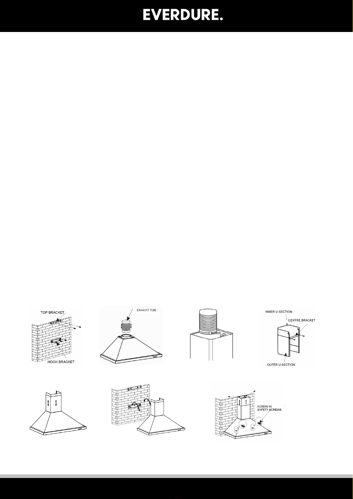
1) Hook Bracket. 2) Centre Bracket (flat). 3) Top Bracket (U-shaped).
Place the hood main unit (no u-shaped section) against the wall at the correct position and mark off the top edge of
the unit. Remove the unit and measure up 22mm to get the top level for the hook bracket. Place the hook bracket
(hooks up) under the mark and mark in the 3 screw holes. Remove the bracket and drill three (3) Ø8mm holes
100mm apart. Insert plastic plugs into the holes and fix the hook bracket onto the wall (see figure 1) with three (3)
40mm screws. Place the hood main unit onto the hooks.
If the position is correct, mark out the positions for the safety screw holes (through the back of the unit), and remove
the hood body. Drill two (2) Ø8mm holes and fit in two (2) plastic plugs.
Fit the exhaust tube to the one way valve (see figures 2 & 3) and secure with a supplied cable tie.
Fit the u-shaped sections together & screw the centre bracket onto the back of the outer u-shaped section using the
supplied 8mm screws (this helps keep the width at the back even with the front) (see figure 4). Place the u-shaped
section onto the main unit and fix in place with two (2) 8mm screws (see figure 5).
Hook the main unit with the u-shaped sections back onto the wall. Mark the positions of the 2 holes needed to fix
the centre bracket to the wall & remove the assembly. Drill two (2) Ø8mm holes and fit in two (2) plastic plugs.
Place the assembly back on the hooks. Fix the centre bracket to the wall with two (2) 40mm screws and fix the body
to the wall with the 30mm screws (through the back of the main unit). Run the loose end of the exhaust tube
outside.
Calculate the final height of the u-shaped section and pull out the inside u-shaped section to a suitable height (see
figure 5) to check. Mark the 2 sides near the top and push the inner section out of the way. Place the top bracket
(slots to the bottom) centred between the 2 marks, mark the 2 screw holes. Remove the bracket and drill two (2)
Ø8mm holes at the marks. Insert plastic plugs into the holes and fix the hook bracket onto the wall (slightly loose)
using 40mm screws.
Pull up the inside u-section to allocate the top bracket correctly, and tighten the screws holding the bracket. Pull
the u-section over the bracket completely and fix into place with 2 screws at the sides (see figure 7). Note: The top
edge of the u-shaped bracket matches the top edge of the u-shaped section – adjust according to your own needs.
For timber framed houses, special care should be taken that all brackets are attached to areas that will support the
weight of the range hood.
NOTE: Remove all protective plastic coatings from the stainless steel surfaces before use.
Figure 1 Figure 2 Figure 3 Figure 4
Figure 5 Figure 6 Figure 7
6
5

EASY DECISION
NOTE: Care should be taken that the range hood is fitted correctly (see diagram below). Incorrect
installation can cause a build up of grease and oils and cause damage to the unit.
NOTE: Remove all protective plastic coatings from the stainless steel surfaces before use.
OPERATING INSTRUCTIONS
Note: Before the unit can be operated, it must be ducted.
Connect the plug into the power.
PUSH BUTTON OPERATED RANGEHOODS
The range hood has indication diagrams to allow you to easily select the fan operating speed required.
Push the low button, indicated by a fan with 3 blades, and the motor will run at a low speed.
Push the medium button, indicated by a fan with 4 blades and the motor will run at a medium speed.
Push the high button, indicated by a fan with 5 blades and the motor will run at a high speed.
Push stop button, indicated by an (O) and the motor will stop.
Push the light button, indicated by a lit globe and the two lights will come on. Push it again and the light
will turn off.
Low
Mid
High
Ligh t
Stop
Low
Mid
High
Ligh t
Stop
Low
Mid
High
Ligh t
Stop
REPLACING THE BULBS
1. Switch the unit off and disconnect from mains power first.
2. Remove the LED globes by pushing in slightly and turning in an anti-clockwise direction.
3. Pull out the LED globe and replace with the same rating and type of globe. Align the globe pins into
the holes in the holder, press in slightly and turn clockwise.
6
EASY DECISION
CLEANING
SAFETY PRECAUTION
Before cleaning your range hood or performing any maintenance, please ensure that the range hood is
turned off at the power point.
Do not use abrasive cleaners to clean the range hood. The use of warm soapy water and a cloth are
recommended.
Ensure that the range hood is cleaned regularly, as a build up of grease and fat may occur otherwise.
The filters on the range hood must be cleaned regularly to maintain efficiency, and prevent grease build
up. The filter mesh is made of a high density Stainless Steel. It is recommended that this is undertaken
every 4 – 6 weeks, depending on frequency of use.
The filters can be cleaned with warm soapy water or a cloth, or they may be washed in a dishwasher. If
washed in a dishwasher, discolouration may occur to the mesh and frame.
Carbon filters (recycling only) should be replaced every 4-6 weeks. These clip on & off the sides of the
motor.
Cleaning of the range hood must be performed as described above, otherwise there is a possibility of a
fire hazard due to grease and fat build up.
TROUBLESHOOTING
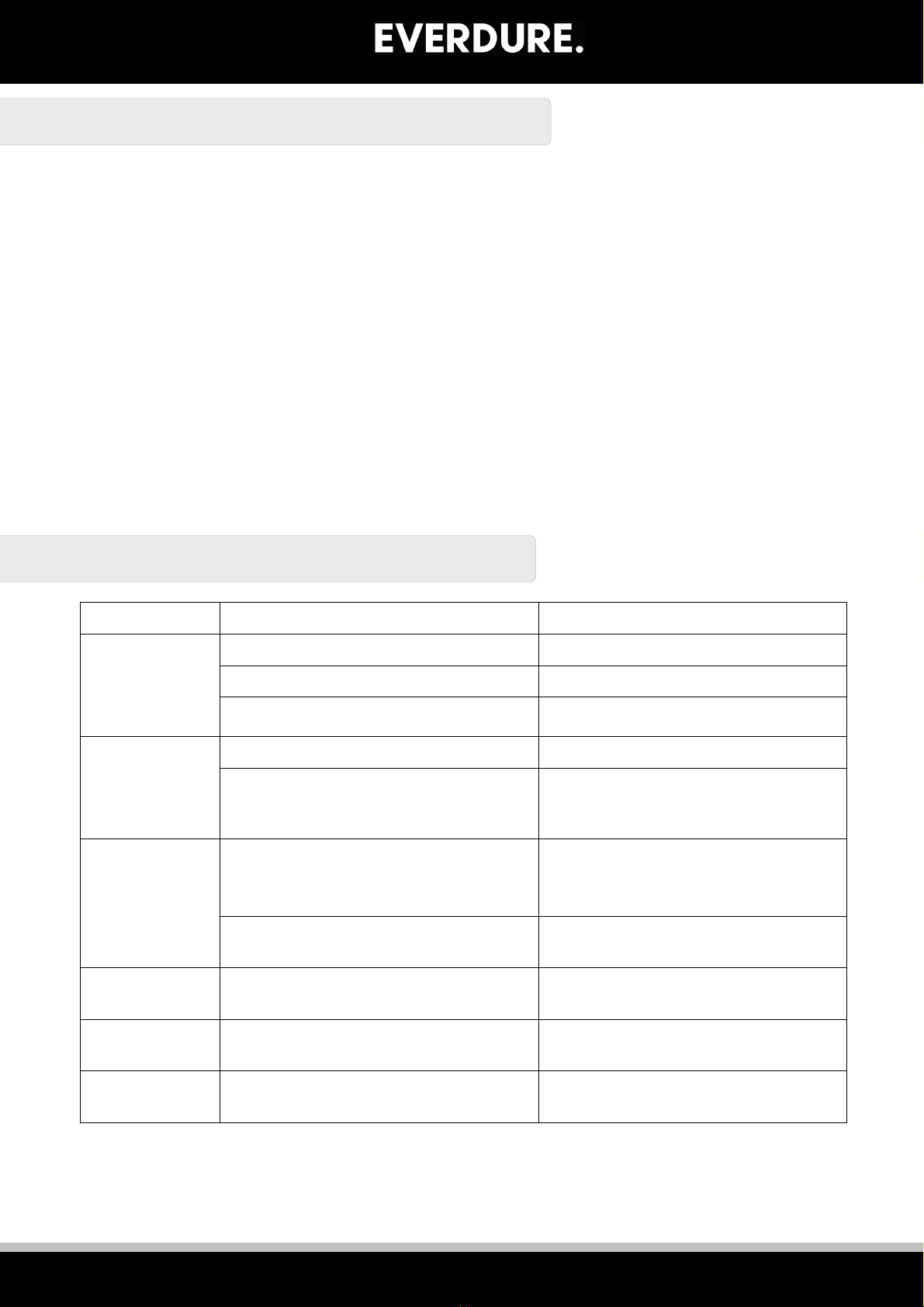
Fault Possible Cause Solution
Light on, but
motor does
not work
Fan switch turned off Select a fan switch position.
Fan switch failed Contact Everdure Service.
Motor failed Contact Everdure Service.
Light does not
work, motor
does not work
House fuses blown Reset/Replace fuses.
Power cord loose or disconnected Refit cord to power outlet.
Switch power outlet on.
Oil leakage
One way valve and the air
ventilation entrance are not tightly
sealed
Take down the one way valve and
seal with sealant.
Leakage from the connection of U-
shaped section and cover
Take U-shaped section down and
seal.
Lights not
working
Broken/Faulty globes Replace globes as per this
instruction.
Insufficient
suction
The distance between the range
hood and the gas top is too far
Refit the range hood to the
correct distance.
The Range
hood inclines
The fixing screw not tight enough Tighten the hanging screw and
make it horizontal.
NOTE: Any electrical repairs to this appliance must conform to your local, state and federal laws.
Please contact the service centre if in any doubt before undertaking any of the above.
Always disconnect the unit from the power source when opening the unit.
7

EASY DECISION
All Service and Assembly Enquiries:
1300 766 066
A division of Shriro Australia Pty Ltd
104 Vanessa St Kingsgrove NSW 2208
AUSTRALIA: 1300 355 541
www.everdure.com
NEW ZEALAND: (09) 415 6000
www.everdure.co.nz
IM Ref: RBES691, 991 18/2017/07FC
FOR INDOOR USE ONLY
This manual suits for next models
1
Table of contents
Other Everdure Ventilation Hood manuals

Everdure
Everdure RBES632 Guide

Everdure
Everdure RBBQ120S Owner's manual

Everdure
Everdure RIES912 Guide

Everdure
Everdure RBEE61 Guide

Everdure
Everdure RBES9012 Guide

Everdure
Everdure RBES62 Guide

Everdure
Everdure RBES692 Guide

Everdure
Everdure RBEE61 User manual

Everdure
Everdure RBES63 Guide

Everdure
Everdure RBES612 Guide


Popular Ventilation Hood manuals by other brands


Franke
Franke FDL 304 W Installation instructions use and care guide

Electrolux
Electrolux WHL6036CN user manual

Lino
Lino AGE 60 WH user manual

Defy
Defy 900 C PREMIUM owner's manual

Siemens
Siemens LF98BIT50 User manual and installation instructions

Miele
Miele DA 3160 EXT Operating and installation instructions