10
2.1 General Descripon, Purpose and Features.
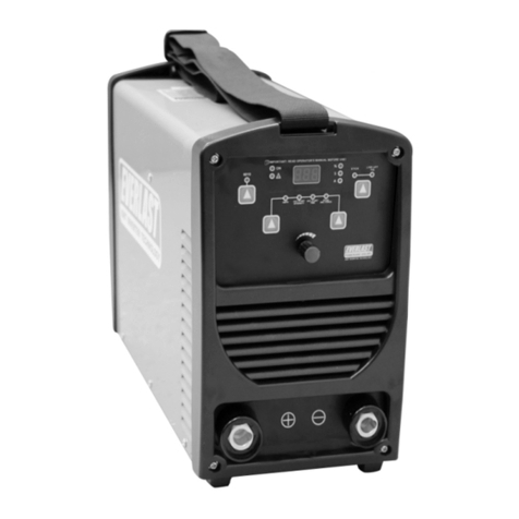
PowerARC 300:
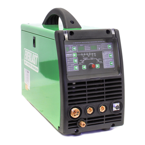
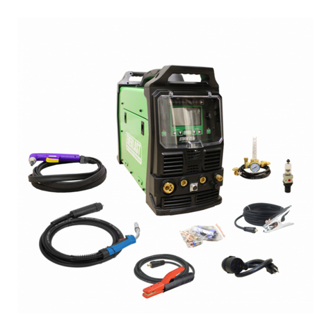
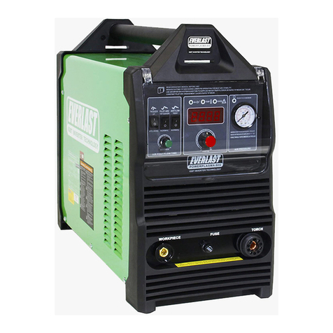
The PowerARC 300 is a compact commercial welder
that incorporates professional features such as adjust-
able hot start and arc force control. The arc is spaer-
free and stable due to heavy duty IGBT components
and advanced inverter design.
The welder is designed to weld with any common cat-
egory of welding rod and works well with electrodes
such as E7018, E6013, E7014, E7024, 309L, and others.
It is suitable for welding in any posion recommend-
ed by the electrode manufacturer.
Equipped with a dedicated reactor circuit and addi-
onal negave polarity port (labeled as E6010), the
PowerARC 300 oers improved performance and pen-
etraon with all cellulosic welding rods compared to
standard inverter designs. This feature makes the
PowerARC 300 a perfect choice for professional use
where E6010/E7010 is commonly used. The E6010
port is also recommended for use with E6011.
The unit is capable of funconing on 1 or 3 phase
standard 208-240V current, 50-60Hz. Measured cur-
rent below 208V at the receptacle is not recommend-
ed. This unit should not be operated on long exten-
sion cords with undersized conductors.
Note: To operate in 6010 mode, the work clamp is
moved from the negave terminal connector to the
connector labeled “6010”. Reverse polarity (DCEP ) is
maintained. There is no need to change the elec-
trode holder posion, unless straight polarity (DCEN)
is desired for special operaons with E6010 or similar
rods. If DCEN (-) is desired, then the posions of the
electrode holder and the work clamp should be
swapped. Check with the manufacturer of the elec-
trodes for polarity recommendaons for each rod.
Hot Start:
The adjustable hot start reduces rod scking and po-
rosity that is created while striking an arc by providing
a controlled surge of amps unl the arc is rmly estab-
lished. Aer the arc is established, the hot start termi-
nates and the welder resumes welding with the select-
ed amp level. The intensity of the hot start contains
more adjustability than is typically required to make
good starts. The numbered scale represents a per-
centage of total available Hot start amperage over and
above the main welding amperage. Useful sengs
for hot start usually range from 3 to 7 (30-70%) on the
knob’s scale.
NOTE: The hot start can blow through the metal if
the seng is too high for the given thickness of the
metal. On thin metals use a lightly penetrang rod
such as an E6013 and a low hot start seng.
Arc Force:
The arc force control can be adjusted to improve arc
performance and allow you to use less amperage over-
all and maintain penetraon. It is also a useful tool
when welding out of posion. The arc force control
reacts to the length of the arc. Typically when the arc
length is shortened (rod held closer to the metal), arc
voltage is lowered due to the characterisc of Con-
stant Current design. In a transformer, this would typi-
cally reduce heat but can lead to the arc snung out
or even a stuck rod. With the PowerARC 300, as the
voltage drops below approximately 20V, the amps are
automacally increased in reacon to the reduced arc
length. This prevents the arc from snung and the
rod from scking. Although the funcon of voltage is
signicant in the welding process, welding is also con-
cerned with overall waage (VxA). The arc force func-
on is also referred to as “dig” or “inductance” in the
industry. Pushing the electrode into the puddle will
increase the heat and penetraon without the arc
going out if the arc force is adjusted correctly. If con-
verng from welding with a transformer based welder
to an inverter welder this funcon will require some
pracce and may feel dierent. Some users who have
been trained on transformers may nd it counter-
intuive inially, but quickly begin to appreciate the
advantage this oers. Arc force requirements vary by
electrode and even by manufacturer. Arc force is set
by feel and experience rather than a given number
and can vary by personal preference and technique.
To maintain strict control of the heat, use the lower
end of the amp range of the recommended by the
electrode manufacturer. Then, increase the arc force
seng enough to maintain the arc while using a short
arc length. This will maintain/increase penetraon,
but conne the arc and heat to a smaller area. Too
much arc force may create random pops or spaer.
Note: Some welding techniques that are maintained
with transformer welders may not be sustainable
with the PowerARC 300ST or other inverter welders.
In order to control the maximum input amps, the
inverter is designed to terminate the arc (shut down
output) if voltage increases over a predetermined arc
voltage at any given amp level. While this prevents
GENERAL SETUP AND OPERATIONSection 2
