10
1.1 General Descripon, Purpose and Features.
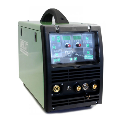
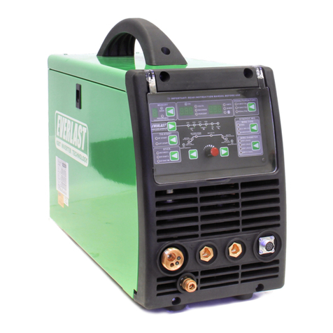
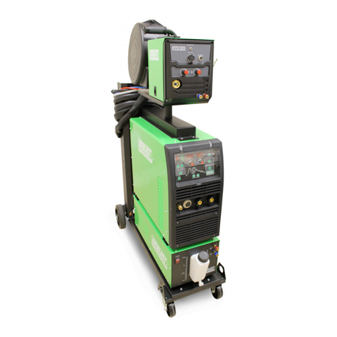
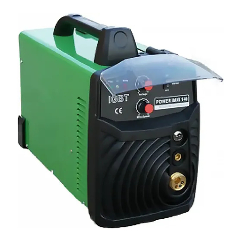
The Power i-MIG 140E is a durable MIG (GMAW) welder
designed for light repair and fabricaon where 240V
service is limited or not praccal. The unit operates on
110/120V single phase input and comes equipped with
a standard 120V NEMA 15-5P plug for convenient use
in almost any standard 120V outlet. The Power i-MIG
140E’s IGBT inverter design is rated for 25% duty cycle
at 140 amps. It is designed to consume less power, pro-
vide beer arc stability and oer beer duty cycle over
transformer welders in the 120V input class. There are
no tapped sengs which prevent ne adjustment of
either voltage or wire speed. Both amps (wire speed)
and voltage are innitely adjustable within their ranges.
1.2 Basic Design and Construcon. The Power i-MIG
140E features an advanced IGBT inverter design, with
plug and play circuits and controls for maximum service-
ability and lifespan. The unit has a full me high speed
fan which maintains temperature levels providing in-
creased duty cycle and performance. A heavy duty
wire feeder mechanism features cast aluminum and
steel construcon for long life. The unit will accommo-
date 4” (1-2lb) and 8” (10-12lb) rolls of wire and fea-
tures rapid tool-free, wire spool installaon. Gun con-
necon is quick with the tool-free design of the Euro
quick connect ng. The Work clamp is equally easy to
install, and features a 25 series DINSE style connector.
For transport or storage both MIG gun and work clamp
can be disconnected in less than 15 seconds. The stand-
ard drive rolls included with the unit are designed for
use with .023”-.035” solid wire. The smaller groove
(.6mm) should be used with .023-.027” wire. The larger
groove (.8mm) should be used with .030 and .035 wire.
For general purpose use, Everlast recommends
that .030” ER70S-6 wire be used for most general pur-
pose welding. This diameter wire and class is designed
to work well with the amp output range that the Power
i-MIG 140E delivers. Special applicaons like aluminum
may be welded with the oponal spool gun. It is possi-
ble to weld aluminum with the main feeder and gun,
but a special gun liner must be purchased and a harder
wire such as 5356 should be used to prevent “bird’s
nesng” of the wire. Stainless can easily be welded
with either the spool gun or the standard gun. Using a
spool gun may be a more praccal choice if welding
smaller projects with stainless or aluminum since both
stainless and aluminum wires are expensive. Either
coated (copper or other coangs) or uncoated steel
wire may be used for welding steel as long as it re-
mains rust-free and clean.
NOTE: For ux core use, special drive rolls with a serrat-
ed design may be purchased from Everlast.
1.3 Installaon. The design of the Power i-MIG 140E is
compact and able to travel almost anywhere 120V service
is available. For maximum output capability, a 30 amp
circuit breaker is needed, with a minimum of a 20 amp
slow trip circuit breaker recommended. If operang on a
15 amp circuit near the maximum amp/volt sengs of
the welder the circuit breaker may trip. If this happens,
reduce the sengs on the welder.
Care and common sense should be taken to make sure
that the welder oers the safest and best performance.
Please note the following items regarding safe operaon:
1) Do not use the welder in damp or wet areas. Perspi-
raon and other forms of water in contact with the
body can increase the risk of electrocuon.
2) Do not use the welder in extremely corrosive environ-
ments. To maintain opmum power transfer, check
main connecons, clamps and cables frequently to
ensure that components are not corroded. Excessive
dirt, corrosion and oxidaon can result in an unstable
arc and excessive heat build-up.
3) Do not kink or ghtly coil the MIG gun or the wire
may not feed properly. Coiling ghtly may even dam-
age the liner or cable if the cable becomes kinked.
Always use the MIG gun with the cable running as
straight as possible. Gentle, natural curves are ac-
ceptable. Do not stand on or roll objects over the
welder cables. Pay close aenon if the welder is on a
rolling cart so that the cables are not accidentally
rolled over when moving it around.
4) Do not pull, hold, or suspend the welder by the gun
or cables. Pick up the welder from the handle only.
5) Due to the light weight and compact size, strap or e
the welder down (over the top) to prevent accidental
overturning while in use on a table or cart.
1.4 Duty Cycle. Duty Cycle is expressed as the percent-
age of me out of 10 minutes at the rated amps/volts that
the welder can weld without an interrupon or break.
Aer this the welder should be allowed to rest the re-
mainder of the 10 minutes. If the duty cycle light is trig-
gered, the welder will stop welding. If this happens, allow
the welder to connue to idle and cool for 15 minutes.
Aer giving the unit me to cool, cycle the power switch
o and back on to reset the welder and resume welding.
Lowering the welder output will increase the duty cycle
duty cycle. This welder has a rang of 25% @ 140 amps.
Lowering the amperage to 90 amps increases the duty
Introduction and Specifications
Section 1
