EVERSPRING EVR SP814 User manual

EVR_SP814
Z-Wave Presence
Detector
Firmware Version : 1.3
Quick Start
SThis device is a Z-Wave Sensor. Inclusion, Exclusion and wakeup are confirmed by three times quickly
hitting the tamper switch on the backside of the case.
Please refer to the chapters below for detailed information about all aspects of the products usage.
What is Z-Wave?
This device is equipped with wireless communication complying to the Z-Wave standard. Z-Wave is the
international standard for wireless communication in smart homes and buildings. It is using the
frequency of 868.42 MHz to realize a very stable and secure communication. Each message is reconfirmed
(two-way communication) and every mains powered node can act as a repeater for other nodes (meshed
network) in case the receiver is not in direct wireless range of the transmitter.
Z-Wave differentiates between Controllers and Slaves. Slaves are either sensors (S) transmitting metered or
measured data or actuators (A) capable to execute an action. Controllers are either static mains powered
controllers (C) also referred to as gateways or mobile battery operated remote controls (R). This results in a
number of possible communication patterns within a Z-Wave network that are partly or completely supported
by a specific device.
1. Controllers control actuators
2. Actuators report change of status back to controller
(c) 2016 Z-Wave Europe GmbH, Antonstr. 3, 09337 Hohenstein-Ernstthal, Germany, All rights reserved, www.zwaveeurope.com - pp 1

3. Sensors report change of status of measured values to controller
4. Sensors directly control actuators
5. Actuators control other actuators
6. Remote controls send signals to static controllers to trigger scenes or other actions
7. Remote controls control other actuators.
There are two different role a controller can have. There is always one single primary controller that is managing the
network and including/excluding devices. The controller may have other functions - like control buttons - as well. All other
controllers don't manage the network itself but can control other devices. They are called secondary controllers. The
image also shows that its not possible to operate a sensor just from a remote control. Sensors only communicate with
static controllers.
Product description
This presence detector using PIR (passive infrared receiver) detects the presence of a person in a room.
The units send information to a controller or any other associated Z-Wave device. Up to 4 devices can be
controlled from this device. The sensor is a battery-powered device, which is in sleeping non-operative
mode unless an action is detected. After a programmable sleeping time the device wakes up and sends a
status information. After this the unit goes back to sleeping modus. Batteries can be changed without
unscrewing the device from the door or frame. The unit will give a visual warning on the device and sends a
warning to the Z-Wave controller, when batteries need to be replaced. The unit offers a tampering control
and sends an alarm message when tampered.
Batteries
The unit is operated by batteries. Use only batteries of correct type. Never mix old and new batteries in the
same device. Used batteries contain hazardous substances and should not be disposed of with household
waste!
Battery Type: 1 * CR2
Installation Guidelines
(c) 2016 Z-Wave Europe GmbH, Antonstr. 3, 09337 Hohenstein-Ernstthal, Germany, All rights reserved, www.zwaveeurope.com - pp 2

1. Release the Sensor from the battery cover by removing the fixing screws.
2. Put the 3 * AA 1.5V batteries in the battery compartment.
3. For mounting use mount plate and the screws.
The detector can be mounted either on a wall or under a ceiling. There is a dedicated lens cover for the two
mounting positions which has to be installed.
The recommended position for wall mounting is at the height of 1.8m from the floor. At this height the
optimum detection range is up to 10m with coverage range of 110 degrees.
(c) 2016 Z-Wave Europe GmbH, Antonstr. 3, 09337 Hohenstein-Ernstthal, Germany, All rights reserved, www.zwaveeurope.com - pp 3

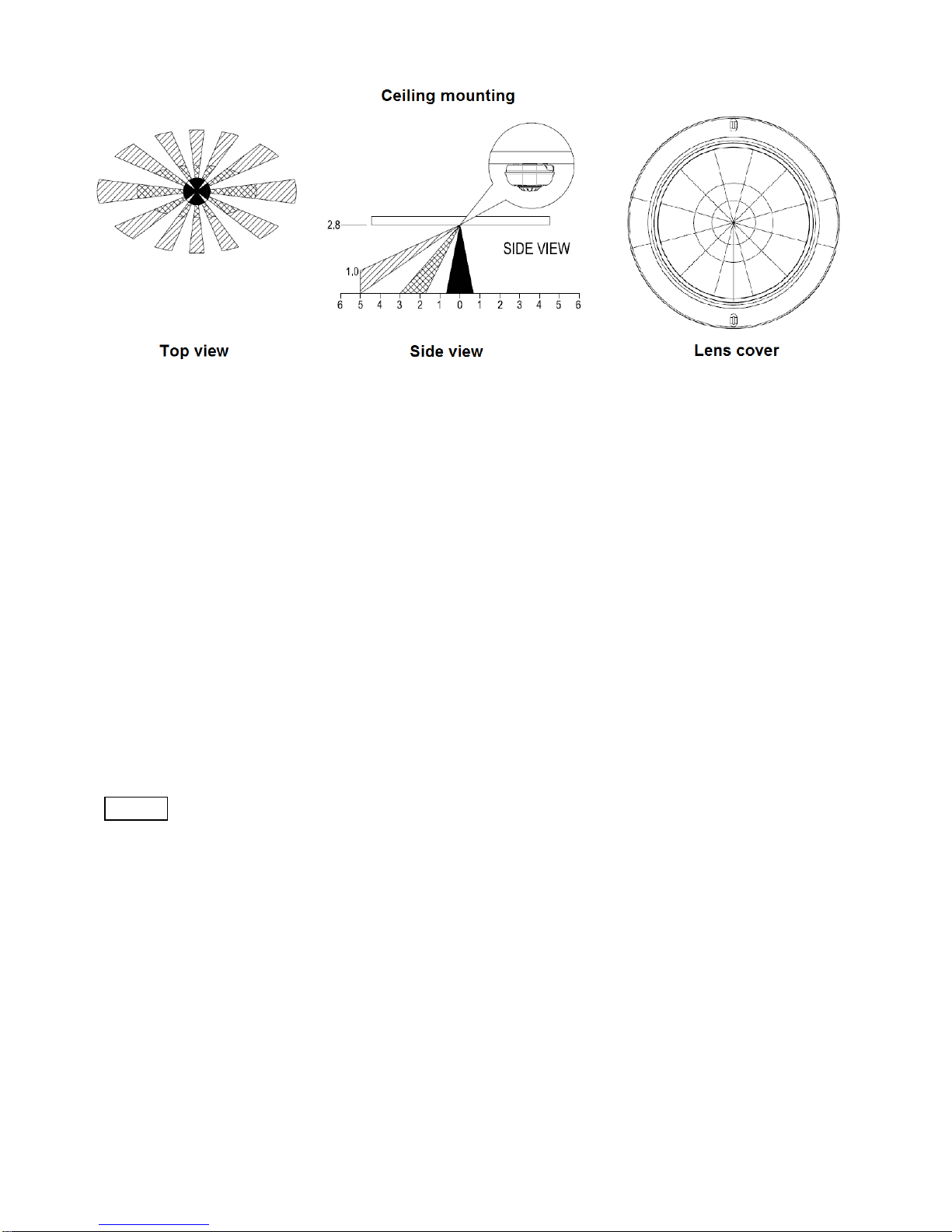
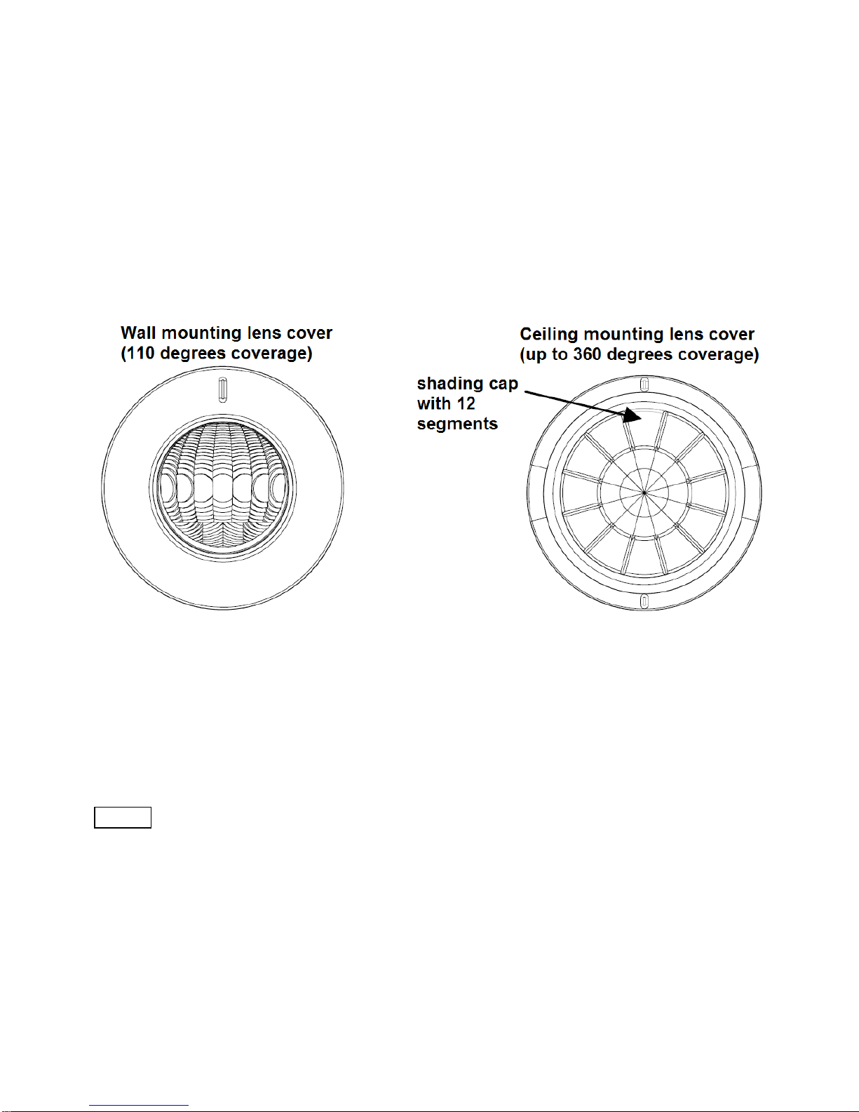
The recommended position for ceiling mounting is at the height of 2.8m from the floor. At this height, the
optimum detection range is up to 5m with coverage range of 360 degrees.
Before selecting a position for a Motion Detector the following points should be noted:
Do not position the detector facing a window or direct sunlight. Motion Detectors are not suitable for use in
conservatories or draughty areas.
Do not position the detector directly above or facing any source of heat, eg: fires, radiators, boiler etc.
Where possible, mount the detector so that the logical path of an intruder would cut across the fan pattern
rather than directly towards the detector.
4. It will take approximately 2 minutes to warm up after battery has been connected. During this period, the
detector beeps once every 3 seconds. When a long beep is sounded with red LED turns on steadily for 5
seconds, it implies warm-up procedure is completed and the detector is ready for detection.
Behavior within the Z-Wave network
IOn factory default the device does not belong to any Z-Wave network. The device needs to join an
existing wireless network to communicate with the devices of this network. This process is called Inclusion.
Devices can also leave a network. This process is called Exclusion. Both processes are initiated by the
primary controller of the Z-Wave network. This controller will be turned into exclusion respective inclusion
mode. Please refer to your primary controllers manual on how to turn your controller into inclusion or
exclusion mode. Only if the primary controller is in inclusion or exclusion mode, this device can join or leave
the network. Leaving the network - i.e. being excluded - sets the device back to factory default.
If the device already belongs to a network, follow the exclusion process before including it in your network.
Otherwise inclusion of this device will fail. If the controller being included was a primary controller, it has to
be reset first.
Make sure that your Z-Wave Controller is in the Inclusion-/Exclusion-Mode. Click three times quickly the
tamper switch behind the battery cover to confirm the process.
(c) 2016 Z-Wave Europe GmbH, Antonstr. 3, 09337 Hohenstein-Ernstthal, Germany, All rights reserved, www.zwaveeurope.com - pp 4

Operating the device
Coverage Range Adjustments:
Two types of lens covers are provided for the detector. Wall-lens cover is to be used when the detector is
wall-mounted, whereas ceiling-lens cover is to be used when the detector is ceiling-mounted. The coverage
range adjustment is only applicable to ceiling-lens cover; choose correct lens cover before mounting. The
shading cap for ceiling mounting is composed of 12 segments for limiting the detection coverage, and
each segment covers detection angle of 30 degrees. Follow the grooves on the cap, cut the cap to a
suitable size and place it onto the ceiling-lens cover. The remaining segments are used for blanking off an
undesirable detection area.
By walking into a protected area the detector will now be triggered each time the detector senses
movement. The orange LED on the detector will be illuminated and the associated appliances will be
activated. For example, siren will be sounded or indication of movement detection will be shown on the
controller. It implies that the unit is working properly.
Wakeup Intervals - how to communicate with the device?
WThis device is battery operated and turned into deep sleep state most of the time to save battery
life time. Communication with the device is limited. In order to communicate with the device, a static
controller Cis needed in the network. This controller will maintain a mailbox for the battery operated devices
and store commands that can not be received during deep sleep state. Without such a controller,
communication may become impossible and/or the battery life time is significantly decreased.
This device will wakeup regularly and announce the wakeup state by sending out a so called Wakeup
Notification. The controller can then empty the mailbox. Therefore, the device needs to be configured with
the desired wakeup interval and the node ID of the controller. If the device was included by a static
controller this controller will usually perform all necessary configurations. The wakeup interval is a tradeoff
between maximal battery life time and the desired responses of the device.
(c) 2016 Z-Wave Europe GmbH, Antonstr. 3, 09337 Hohenstein-Ernstthal, Germany, All rights reserved, www.zwaveeurope.com - pp 5

Click three times quickly on the tamper switch behind the battery cover or a detected action by the sensor
will wake up the device and keep it awake.
It is possible to set the node ID to 255 to send wakeup notifications as broadcast. In this mode device takes more time to
go to sleep and drains battery faster, but can notify all it's direct neighbors about a wakeup.
Node Information Frame
NI The Node Information Frame is the business card of a Z-Wave device. It contains information
about the device type and the technical capabilities. The inclusion and exclusion of the device is confirmed
by sending out a Node Information Frame. Beside this it may be needed for certain network operations to
send out a Node Information Frame.
Click three times quickly on the tamper switch behind the battery cover or a detected action by the sensor
sends a Node Information Frame.
Associations
AZ-Wave devices control other Z-Wave devices. The relationship between one device controlling
another device is called association. In order to control a different device, the controlling device needs to
maintain a list of devices that will receive controlling commands. These lists are called association groups
and they are always related to certain events (e.g. button pressed, sensor triggers, ...). In case the event
happens all devices stored in the respective association group will receive a common wireless command.
Association Groups:
1 Devices controlled by open/close events (max. nodes in group: 5)
Command Classes
Supported Command Classes
Basic (version 1)
Battery (version 1)
Wake Up (version 1)
Association (version 1)
Version (version 1)
Binary Sensor (version 1)
Alarm (version 1)
Manufacturer Specific (version 1)
Controlled Command Classes
Basic (version 1)
(c) 2016 Z-Wave Europe GmbH, Antonstr. 3, 09337 Hohenstein-Ernstthal, Germany, All rights reserved, www.zwaveeurope.com - pp 6

Alarm (version 1)
Technical Data
Battery Type 1 * CR2
Explorer Frame Support No
SDK 5.02 pl2
Device Type Slave with routing capabilities
Generic Device Class Binary Sensor
Specific Device Class Routing Binary Sensor
Routing No
FLiRS No
Firmware Version 1.3
Explanation of Z-Wave specific terms
Controller — is a Z-Wave device with capabilities to manage the network. Controllers are typically
Gateways, Remote Controls or battery operated wall controllers.
Slave — is a Z-Wave device without capabilities to manage the network. Slaves can be sensors, actuators
and even remote controls.
Primary Controller — is the central organizer of the network. It must be a controller. There can be only one
primary controller in a Z-Wave network.
Inclusion — is the process of bringing new Z-Wave devices into a network.
Exclusion — is the process of removing Z-Wave devices from the network.
Association — is a control relationship between a controlling device and a controlled device.
Wakeup Notification — is a special wireless message issued by a Z-Wave device to annonces that is is
able to communicate.
Node Information Frame — is a special wireless message issued by a Z_Wave device to announce its
capabilities and functions.
Disposal Guidelines
The product contains batteries. Please remove the batteries when the device is not used.
Do not dispose of electrical appliances as unsorted municipal waste, use separate collection facilities.
Contact your local government for information regarding the collection systems available. If electrical
appliances are disposed of in landfills or dumps, hazardous substances can leak into the groundwater and
get into the food chain, damaging your health and well-being.
(c) 2016 Z-Wave Europe GmbH, Antonstr. 3, 09337 Hohenstein-Ernstthal, Germany, All rights reserved, www.zwaveeurope.com - pp 7
Table of contents
Other EVERSPRING Accessories manuals