7780R2x1-ASI-CS-2
7780R2x1-ASI-CS-2 Dual Compressed TS Automatic Smart Switch
Revision 1.4 Page iii
6.8. FAULT CONTROL................................................................................................................................44
6.9. TRIGGER FAULTS TAB......................................................................................................................45
7. TROUBLESHOOTING.................................................................................................................. 46
7.1. VLPRO DOES NOT DISPLAY THE 7780R2X1-ASI-CS-2 ALARMS..................................................46
7.2. UPDATING VLPRO SERVER JAR FILE.............................................................................................46
7.3. SWITCHING LOGIC.............................................................................................................................48
7.3.1. Special Cases........................................................................................................... 48
7.3.2. GOP Repeat Mode – Disabled ................................................................................. 49
7.3.3. GOP Repeat Mode – Enabled.................................................................................. 51
7.4. MY STREAMS ARE MORE THAN 3 SECONDS DELAYED ..............................................................52
8. ABBREVIATIONS......................................................................................................................... 53
Figures
Figure 1-1: 7780R2x1-ASI-CS-2 Block Diagram..............................................................................................6
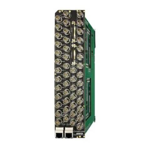
Figure 2-1: 7780R2x1-ASI-CS-2 Rear Plate ....................................................................................................7
Figure 2-2: 7700 Chassis..................................................................................................................................9
Figure 2-3: COM Port Properties Window......................................................................................................10
Figure 2-4: HyperTerminal Main Menu...........................................................................................................11
Figure 2-5: Network Configuration Sub-Menu................................................................................................12
Figure 4-1: VistaLINK®PRO Hardware Configuration....................................................................................17
Figure 5-1: VistaLINK®PRO Input Status Tab ...............................................................................................18
Figure 5-2: VistaLINK®PRO Switch Control Tab ...........................................................................................19
Figure 5-3: VistaLINK®PRO Network Statistics Tab......................................................................................25
Figure 5-4: Clear Network Stats Menu Item ...................................................................................................25
Figure 5-5: VistaLINK®PRO Switch Faults ....................................................................................................26
Figure 5-6: VistaLINK®PRO SNMP Configuration Tab..................................................................................27
Figure 6-1: VistaLINK®PRO Bitrate View Tab ...............................................................................................28
Figure 6-2: VistaLINK®PRO Input Configuration Tab....................................................................................29
Figure 6-3: VistaLINK®PRO Input Monitor Tab..............................................................................................30
Figure 6-4: VistaLINK®PRO TS Syntax Errors – P1 & P2 Tab......................................................................32
Figure 6-5: VistaLINK®PRO Switch Thresholds ............................................................................................35
Figure 6-6: VistaLINK®PRO TS Syntax Errors - P3.......................................................................................36
Figure 6-7: VistaLINK®PRO P3 DVB Switch Thresholds ..............................................................................39
Figure 6-8: VistaLINK®PRO Template Check Tab........................................................................................41
Figure 6-9: VistaLINK®PRO Fault Control Tab..............................................................................................44
Figure 6-10: VistaLINK®PRO Trigger Faults Tab..........................................................................................45
Figure 7-1: VistaLINK®PRO Server...............................................................................................................46
Figure 7-2: VistaLINK®PRO Applying JAR Updates......................................................................................47
Figure 7-3: Restart Alarm Server Window......................................................................................................47
Tables
Table 2-1: Standard RJ-45 Wiring Color Codes...............................................................................................8
Table 5-1: ASI Stream Types .........................................................................................................................21
Table 6-1: TR 101 290 DVB Reference Values..............................................................................................40
Table 7-1: GOP Repeat Mode – Disabled......................................................................................................50
Table 7-2: GOP Repeat Mode – Enabled.......................................................................................................52

