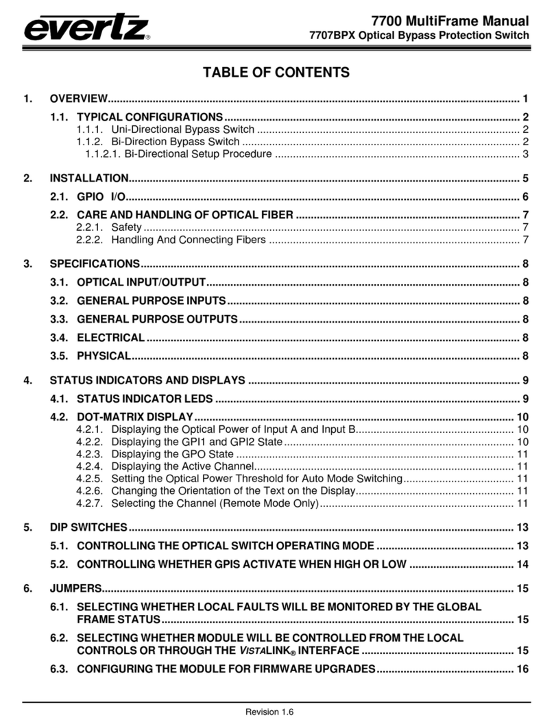
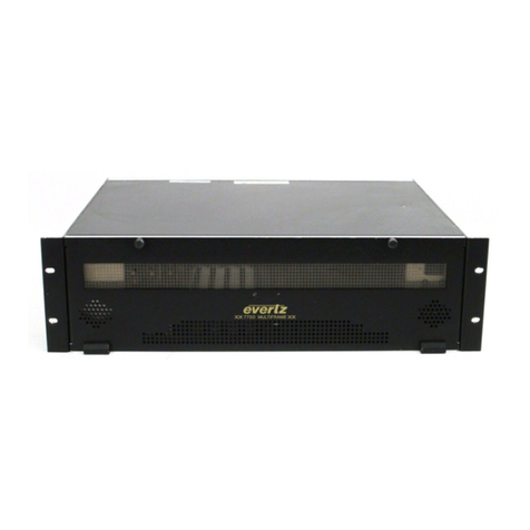
evertz 7700 Series User manual

7700 MultiFrame Manual
7702/3BPX-IF Intermediate Frequency Bypass Protection Switch
Revision 1.2
TABLE OF CONTENTS
1. OVERVIEW.......................................................................................................................................... 1
1.1. TYPICAL CONFIGURATION...................................................................................................... 3
1.1.1. Uni-directional Bypass Switch .......................................................................................... 3
2. INSTALLATION................................................................................................................................... 4
2.1. GPIO........................................................................................................................................... 5
3. SPECIFICATIONS............................................................................................................................... 6
3.1. RF INPUT/OUTPUT.................................................................................................................... 6
3.2. GENERAL PURPOSE INPUTS.................................................................................................. 6
3.3. GENERAL PURPOSE OUTPUTS.............................................................................................. 6
3.4. ELECTRICAL ............................................................................................................................. 6
3.5. PHYSICAL.................................................................................................................................. 6
4. STATUS INDICATORS AND DISPLAYS ........................................................................................... 7
4.1. STATUS INDICATOR LEDS....................................................................................................... 7
4.2. DOT-MATRIX DISPLAY (7703BPX-IF ONLY ).......................................................................... 7
4.2.1. Displaying the RF Power of Input A and Input B .............................................................. 8
4.2.2. Displaying the GPI1 and GPI2 State ................................................................................ 9
4.2.3. Displaying the Active Channel.......................................................................................... 9
4.2.4. Displaying the Operating Mode Status............................................................................. 9
4.2.5. Displaying the Firmware Version...................................................................................... 9
4.2.6. Selecting the Switch Mode ............................................................................................. 10
4.2.7. Setting the RF Power Threshold for Auto Mode Switching............................................. 10
4.2.8. Changing the Orientation of the Text on the Display...................................................... 11
4.2.9. Selecting High or Low as GPI Active State..................................................................... 11
4.2.10.Performing a Factory Reset........................................................................................... 11
5. DIP SWITCHES ( 7702BPX-IF ONLY ).............................................................................................12
5.1. CONTROLLING THE SWITCH OPERATING MODE .............................................................. 12
5.2. CONTROLLING THE SWITCH USING GPI INPUTS................................................................ 13
6. JUMPERS.......................................................................................................................................... 14
6.1. SELECTING WHETHER LOCAL FAULTS WILL BE MONITORED
BY THE GLOBAL FRAME STATUS ........................................................................................ 15
6.2. MONITORING AND CONTROL OF 7703BPX-IF CARDS THROUGH SNMP
OR CARD EDGE MENU SYSTEM............................................................................................ 15
6.3. CONFIGURING THE MODULE FOR FIRMWARE UPGRADES (7703BPX-IF ONLY) ............ 15
7700 MultiFrame Manual
7702/3BPX-IF Intermediate Frequency Bypass Protection Switch
Revision 1.2
6.4. SELECTING THE GPI PULL-UP VOLTAGE ........................................................................... 15
6.5. USING THE GPO OUTPUTS ................................................................................................... 15
7. VISTALINK®REMOTE MONITORING/CONTROL (7703BPX-IF ONLY)......................................... 16
7.1. WHAT IS VISTALINK®?............................................................................................................... 16
7.2. VISTALINK®MONITORED PARAMETERS .............................................................................. 16
7.3. VISTALINK®CONTROLLED PARAMETERS ........................................................................... 17
7.4. VISTALINK®TRAPS.................................................................................................................. 17
Figures
Figure 1-1: 7703BPX-IF Block Diagram................................................................................................................2
Figure 1-2: 7702BPX-IF Block Diagram................................................................................................................2
Figure 1-3: Typical Application of Protection Switch in IF Uplink Transport System............................................3
Figure 2-1: 7702BPX-IF and 7703BPX-IF Rear Panels........................................................................................4
Figure 2-2: GPI Input Circuitry ..............................................................................................................................5
Figure 2-3: GPO Configuration .............................................................................................................................5
Figure 6-1: Location of Jumpers – 7702BPX-IF..................................................................................................14
Figure 6-2: Location of Jumpers – 7703BPX-IF..................................................................................................14
Tables
Table 4-1: Setting the Switch Mode via the SET/MODE menu...........................................................................10
Table 4-2: Controlling the Switch Using GPI Inputs – 7703BPX-IF....................................................................10
Table 5-1: DIP Switch Functions.........................................................................................................................12
Table 5-2: Operating Mode Switch Settings .......................................................................................................12
Table 5-3: GPI Active State Switch Settings.......................................................................................................13
Table 5-4: Controlling the switch Using GPI Inputs – 7702BPX-IF.....................................................................13
Table 7-1: VistaLINK®Monitored Parameters.....................................................................................................16
Table 7-2: VistaLINK®Controlled Parameters....................................................................................................17
Table 7-3: VistaLINK®Traps...............................................................................................................................17

7700 MultiFrame Manual
7702/3BPX-IF Intermediate Frequency Bypass Protection Switch
Revision 1.2
REVISION HISTORY
REVISION DESCRIPTION DATE
1.0 First Version Jan 05
1.1 Minor typographical errors fixed Aug 05
1.2 Updated specs and menu formatting Sept 09
Information contained in this manual is believed to be accurate and reliable. However, Evertz assumes no responsibility for the use thereof nor for
the rights of third parties, which may be effected in any way by the use thereof. Any representations in this document concerning performance of
Evertz products are for informational use only and are not warranties of future performance, either express or implied. The only warranty offered by
Evertz in relation to this product is the Evertz standard limited warranty, stated in the sales contract or order confirmation form.
Although every attempt has been made to accurately describe the features, installation and operation of this product in this manual, no warranty is
granted nor liability assumed in relation to any errors or omissions unless specifically undertaken in the Evertz sales contract or order confirmation.
Information contained in this manual is periodically updated and changes will be incorporated into subsequent editions. If you encounter an error,
please notify Evertz Customer Service department. Evertz reserves the right, without notice or liability, to make changes in equipment design or
specifications.

7700 MultiFrame Manual
7702/3BPX-IF Intermediate Frequency Bypass Protection Switch
Revision 1.2
This page left intentionally blank

7700 MultiFrame Manual
7702/3BPX-IF Intermediate Frequency Bypass Protection Switch
Revision 1.2 7702/3BPX-IF-1
1. OVERVIEW
The 7702BPX-IF and 7703BPX-IF modules are wide band 2 x 1 RF protection switches that provide auto-
changeover capability by detecting a change in the input power level. Manual control or automation
control via the GPI port is also provided. This is a latching switch which maintains switch state on loss of
power. It is designed for intermediate frequency satellite earth station links or CATV signals and operates
over a wide frequency range of 10MHz to 850MHz.
The 7703BPX-IF model has integrated VistaLINK®technology for remote control and monitoring capability
via SNMP. This provides the user with the ability to locally or remotely configure and monitor parameters
such as module status, selected input, power level and switching threshold.
In the auto-changeover application, both products can be configured to have a Main input and a Standby
input. In this configuration, it will automatically switch to the Standby input when the Main input power is
weak or lost. Switch-back to the Main input when the signal is re-established may be configured to occur
automatically or manually. The 7702/7702BPX-IF may also be configured to operate manually as a 2:1
switch, which may be controlled locally or remotely via GPI or SNMP (7703 model only).
The 7702BPX-IF and 7703BPX-IF occupy one card slot and can be housed in a 1RU frame that will hold
up to 3 modules, a 3RU frame that will hold up to 15 modules, a 350FR portable frame that will hold up to
7 modules or a standalone enclosure which holds 1 module.
Features:
Wide operating frequency range, 10MHz to 850MHz
Intelligent auto switching with input power detection
User-definable threshold levels on 7703BPX-IF version
Maintains switch state and RF channel on loss of power to card or frame
Supports automatic or manual control via GPI or SNMP on 7703BPX-IF
Switch state indication via GPO
Card edge LEDs indicate active input channels, output channel and power levels below threshold
Fully hot-swappable from front of frame
Comprehensive signal and card status monitoring via four digit card edge display or remotely
through SNMP and VistaLINK®on 7703 version
VistaLINK®capability is available when 7703BPX-IF modules are used with the 3RU 7800FR or
350FR portable frame and a 7700FC VistaLINK®Frame Controller module in slot 1 of the frame

7700 MultiFrame Manual
7702/3BPX-IF Intermediate Frequency Bypass Protection Switch
7702/3BPX-IF-2 Revision 1.2
VistaLINK
Interface
Power
Monitor
Passive
Splitter
Passive
Splitter Power
Monitor
Controller
Module
Status
GPI / GPO
Inputs &
Outputs
RF
Switch
RF
Input A
RF
Input B
Local
Indicators
4 Digit
Dot
Matrix
Display
RF
Output
Figure 1-1: 7703BPX-IF Block Diagram
Power
Monitor
Passive
Splitter
Passive
Splitter Power
Monitor Controller
Module
Status
RF
Switch
RF
Input A
RF
Input B
Local
Indicators Dip
Switch
RF
Output
GPI / GPO
Inputs &
Outputs
Figure 1-2: 7702BPX-IF Block Diagram

7700 MultiFrame Manual
7702/3BPX-IF Intermediate Frequency Bypass Protection Switch
Revision 1.2 7702/3BPX-IF-3
1.1. TYPICAL CONFIGURATION
1.1.1. Uni-directional Bypass Switch
Optical
Receiver
7707IFRA
Optical
Transmitter
7707IFTA 7702/3BPX-IF
HPA
7702/3DA4-RF Video
Modulator
Video
Modulator
7702/3DA4-RF
UPC Optical
Receiver
7707IFRA
Optical
Transmitter
7707IFTA
7702/3BPX-IF
Figure 1-3: Typical Application of Protection Switch in IF Uplink Transport System
Figure 1-3 illustrates the use of the BPX-IF as a protection switch in an earth station IF satellite uplink
transport system. The modulated video signal at 70 / 140MHz intermediate frequency is fed into the
Evertz Microsystems 7702/3DA4-RF 1x4 active splitter for distribution to multiple transmit paths. Two
signals from different sources are directed to the 7702/3BPX-IF, one acting as a primary source and the
other as a backup signal if the primary fails. The IF signal is then transported over optical fiber up to 60km
using the optical transmitter / receiver pair, 7707IFTA and 7707IFRA from Evertz Microsystems from the
NOC ( Network Operations Centre ) to the dish. The protection switch can also be used to provide
redundancy to the fiber optic link as shown in the above diagram. This protects against a fiber break or
optical transmitter / receiver failure. The switch is a latching switch, maintaining the switch state on loss of
power.

7700 MultiFrame Manual
7702/3BPX-IF Intermediate Frequency Bypass Protection Switch
7702/3BPX-IF-4 Revision 1.2
2. INSTALLATION
The 7702BPX-IF and 7703BPX-IF both come with a companion rear plate that has three BNC (F type
optional) connectors and a six pin terminal strip. For information on mounting the rear plate and inserting
the module into the frame see section 3 of the 7700FR chapter.
Figure 2-1: 7702BPX-IF and 7703BPX-IF Rear Panels
INPUT A, B: The two BNC ( F type optional ) connectors are RF inputs that accept frequencies over the
range of 10MHz to 850MHz. The A connector is for the Main input and the B connector is
for the Standby input.
OUTPUT: This BNC ( F type optional ) connector is the output from the switch.

7700 MultiFrame Manual
7702/3BPX-IF Intermediate Frequency Bypass Protection Switch
Revision 1.2 7702/3BPX-IF-5
2.1. GPIO
A 6-pin removable terminal block labeled GPIO contains 2 GPI inputs and 2 GPI outputs
GPI: The two top pins on the 6 pin terminal strip are used for two General Purpose inputs (GPI). The
GPIs can be configured as active high or low by setting DIP switch 3. GPIs are active low
when Dip switch 3 is Off and GPIs are active high when Dip switch 3 is in On ( positioned
closest to the PCB ). The GPI inputs are opto isolated with an internal pullup resistor to +5V or
+12V as shown in Figure 2-2. See section 6.4 for information on selecting the pull-up voltage.
GPI
GND
GPI
Command
+ 12
VDC
to
internal
circuit
220 Ohm
+ 5
VDC
LO HI
Current
Limiter
Figure 2-2: GPI Input Circuitry
GPO: The NC, NO and COM pins on the 6 pin terminal strip are used for the General Purpose Output
(GPO). The GPO output is a set of normally open and normally closed relay contacts as
shown in Figure 2-3.
NO GPO Contact
GPO Common
from
internal
circuit
NC GPO Contact
Figure 2-3: GPO Configuration

7700 MultiFrame Manual
7702/3BPX-IF Intermediate Frequency Bypass Protection Switch
7702/3BPX-IF-6 Revision 1.2
3. SPECIFICATIONS
3.1. RF INPUT/OUTPUT
Inputs: 2
Outputs: 1
Connectors: BNC per IEC 60169-8 Annex A ( F type optional )
I/O Impedance: 75Ω, 50Ωoptional
Frequency Response:
10-200MHz: < ±0.25dB
10-850MHz: < ±0.5dB
Insertion Loss: < 4dB
Return Loss:
10-200MHz: < 15dB
10-850MHz: < 17dB
Isolation: > 50dB (10-850MHz)
Input Power Range: 0dBm to -50dBm
3.2. GENERAL PURPOSE INPUTS
Number of Inputs: 2
Type: Opto-isolated, active low with internal pull-ups to +5V
Connector: 2 pins plus ground on 6 pin terminal strip
Signal Level:
+5V Pullup: Low: -5 to +2.5 VDC, High: 3.5 to 10 VDC
+12V Pullup: Low: -5 to +9.5 VDC, High: 10.5 to 15 VDC
Max Sink Current: (input shorted to ground) 15 mA
Max Leakage Current for Input High: 200 µA
3.3. GENERAL PURPOSE OUTPUTS
Number of Outputs: 1
Type: “Dry Contact” relay contacts - normally open and normally closed contact provided
Connector: 3 pins on 6 pin terminal strip
3.4. ELECTRICAL
Voltage: +12VDC
Power: 3 Watts
EMI/RFI: Complies with FCC regulations for class A devices
Complies with EU EMC directive
3.5. PHYSICAL
7700 or 7701 frame mounting:
Number of slots: 1

7700 MultiFrame Manual
7702/3BPX-IF Intermediate Frequency Bypass Protection Switch
Revision 1.2 7702/3BPX-IF-7
4. STATUS INDICATORS AND DISPLAYS
The 7702BPX-IF and 7703BPX-IF have 9 LED Status indicators on the front card edge to show
operational status of the card at a glance. The 7703BPX-IF also has an alphanumeric dot matrix display,
toggle switch and push button. The card edge pushbutton and toggle switch is for user input. Figure 6-1
shows the location of the LEDs and card edge controls.
4.1. STATUS INDICATOR LEDS
Two large LEDs on the front of the board indicate the general health of the module
LOCAL FAULT: This Red LED indicates poor module health and will be On during the absence of
a valid IF input signal or if a board power fault exists (i.e.: a blown fuse). The
LOCAL FAULT indication can also be reported to the frame through the FRAME
STATUS jumper.
MODULE OK: This Green LED indicates good module health. It will be On when a valid IF input
signal is present, and the board power is good.
There are four small LEDs beside the LED display that indicate the status of the module.
CH A ACTIVE: This Green LED indicates that Channel A has power above threshold.
CH A PWR LOW: This Red LED indicates when the received power on Channel A is below the
switching threshold set for Channel A. (See section 4.2.7)
CH B ACTIVE: This Green LED indicates that Channel B has power above threshold.
CH B PWR LOW: This Red LED indicates when the received power on Channel B is below the
switching threshold set for Channel B. (See section 4.2.7)
OUTPUT INDICATOR: This Green LED is ON when Channel A is connected to the output and OFF when
Channel B is connected to the output.
AUTO MODE: This Yellow LED is ON when Auto Mode is selected and OFF when Auto mode is
not selected.
SWITCH BACK: This Yellow LED is OFF when Switch Back Mode is selected (For auto mode
only).
4.2. DOT-MATRIX DISPLAY ( 7703BPX-IF ONLY )
Additional signal and status monitoring and control over the card’s parameters are provided via the 4-digit
alphanumeric display located on the card edge. To select one of two menu display modes, press the
toggle switch. To go to the sub-menu press the pushbutton once to select the sub-menu display, ans then
press the toggle switch. When in a particular display mode, press the pushbutton to display the value and
use the toggle switch to change values (if applicable) and to see what status is being displayed for the
particular menu item. The following display messages indicate what is being displayed. The details of
each of the displays are described in the sections 4.2.1 to 4.2.6.

7700 MultiFrame Manual
7702/3BPX-IF Intermediate Frequency Bypass Protection Switch
7702/3BPX-IF-8 Revision 1.2
OK
MON
PWRA Display the input power of channel A
PWRB Display the input power of channel B
GPI1 GPI1 state
GPI2 GPI2 state
CHAN Indicates whether input A or input B is the active channel
MODE Indicates operational mode status
AUTO Indicates Auto – No switch back
ASB Indicates Auto - Switch Back
EXT Indicates external (GPI ) mode status
CHAN A Indicates external mode status
CHAN B Indicates external mode status
VER Display firmware version
SET
MODE Sets operating mode
AUTO Auto – No switch back
ASB Auto - Switch Back
EXT External ( GPI ) mode
CHAN A Switch to channel A
CHAN B Switch to channel B
MINA Set Channel A’s minimum power threshold
MINB Set Channel B’s minimum power threshold
DISP Set Display Orientation ( HORZ / VERT )
ACTV Sets High or Low as GPI Active State
FRST Factory Reset
4.2.1. Displaying the RF Power of Input A and Input B
The 7703BPX-IF detects the input RF power of both inputs and displays this on the four-digit card edge
display. Enter the MON menu, then toggle to PWRA or PWRB, and press the pushbutton. This displays
the corresponding input power. The following list describes possible displays and their meaning.
MON
PWRA
PWRB
OVR
-10 to -50
LOW
The video standard will be displayed from the list below:
OVR Indicates RF input power is above threshold
-10 to –50 Numerical value of RF input power in dBm
LOW Indicates RF input power is below threshold
"
The power reading is reliable to –45dBm.
Do not set the threshold for switching below –45dBm.

7700 MultiFrame Manual
7702/3BPX-IF Intermediate Frequency Bypass Protection Switch
Revision 1.2 7702/3BPX-IF-9
4.2.2. Displaying the GPI1 and GPI2 State
The 7703BPX-IF detects the status of the GPI inputs and displays this on the four-digit card edge display.
Enter the MON menu item, then use the toggle switch to select GPI1 or GPI2, then press the pushbutton.
MON
GPI1
GPI2
High
Low
The following list describes the possible menu display options:
HIGH Indicates that the selected GPI input is high
LOW Indicates that the selected GPI input is low
4.2.3. Displaying the Active Channel
The 7703BPX-IF detects the active channel and displays this on the four-digit card edge display. Enter
the MON menu item, then use the toggle switch to select CHAN, and press the pushbutton.
MON
CHAN
CH A
CH B
The following list describes the possible menu display options:
CH A Indicates that A is active channel
CH B Indicates that B is active channel
4.2.4. Displaying the Operating Mode Status
The 7703BPX-LB detects the operating mode status and displays this on the four-digit card edge display.
Enter the MON menu item, then use the toggle switch to select GPI1 or GPI2, and press the pushbutton.
MON
MODE
AUTO
ASB
EXT
CH A
CH B
The following list describes the possible menu display options:
AUTO Indicates Auto – No switch back
ASB Indicates that A is active channel
EXT Indicates external (GPI) mode status
CHAN A Indicates external mode status
CHAN B Indicates external mode status
4.2.5. Displaying the Firmware Version
To view the current firmware version enter the MON menu, then toggle to the VER menu option.
MON
VER Displays the current firmware version on the card

7700 MultiFrame Manual
7702/3BPX-IF Intermediate Frequency Bypass Protection Switch
7702/3BPX-IF-10 Revision 1.2
4.2.6. Selecting the Switch Mode
To select the desired operating mode, navigate to the SET menu and toggle to the MODE menu item. The
following list of modes will be displayed (AUTO, ASB, CH A (Manual), CH B (Manual) or EXT (External
Mode)). Table 4-1 shows the operating modes for each selection.
SETTING MODE DESCRIPTION
AUTO Auto
If channel A is active, it will switch to channel B if A falls below
threshold (and if B is above threshold). If A rises above threshold,
channel B will remain active channel, unless channel B falls below
threshold, then the module will switch back to A (if A is above
threshold)
ASB Auto Switch
Back
Channel A is the main input and Channel B is standby. If A falls
below threshold, it will switch to B (if B is above threshold). When A
returns to a level above threshold, it will switch back to A.
CH A or CH B Manual The active channel is selected as either Channel A or Channel B
EXT External (GPI)
Operating mode is selectable via the GPIs
Table 4-1: Setting the Switch Mode via the SET/MODE menu
To operate in external (GPI) mode, set the EXT item to ON. The Switch mode is now selectable based on
the GPI1 and GPI2 settings. Table 4-2 shows the settings to achieve the desired switch state. The Auto
Switch Back and No Auto Switch Back Modes operate as described in Table 4-1. The SET / ACTV menu
item controls whether the active GPI state is high or low.
Operating Manual Auto
Mode CH A CH B Switch Back No Switch Back
GPI1 Active Inactive Inactive Active
GPI2 Inactive Active Inactive Active
Table 4-2: Controlling the Switch Using GPI Inputs – 7703BPX-IF
4.2.7. Setting the RF Power Threshold for Auto Mode Switching
The MINA and MINB display in the SET menu allows the user to set the minimum input RF power
threshold for each channel before the auto switch function will occur. To increase the RF power threshold
press the toggle switch up. To decrease the RF power threshold press the toggle switch down. The
threshold will be shown in dBm.
SET
MINA
MINB
dbm threshold
The threshold will be shown in dBm.
"The power reading is reliable to –45dBm.
Do not set the threshold for switching below –45dBm.

7700 MultiFrame Manual
7702/3BPX-IF Intermediate Frequency Bypass Protection Switch
Revision 1.2 7702/3BPX-IF-11
4.2.8. Changing the Orientation of the Text on the Display
The DISP display allows the user to select a horizontal or vertical orientation for the displays to
accommodate mounting the module in the 3RU or 1RU frames. To change the orientation of the display
press the toggle switch.
SET
DISP
HORZ
VERT
The following list describes the available menu options.
VERT Vertical orientation suitable for modules installed in the 3RU frame
HOR Horizontal orientation suitable for modules installed in the 1RU frame
4.2.9. Selecting High or Low as GPI Active State
The 7703BPX-IF allows setting the Active state of the GPIs as high or low. Enter the SET menu and
toggle to the ACTV menu item.
SET
ACTV
HIGH
LOW
The following list describes the available menu options.
HIGH Sets the selected GPI input to high
LOW Sets the selected GPI input to low
4.2.10. Performing a Factory Reset
The 7703BPX-IF allows performing a factory reset of card parameters. Enter the SET menu and navigate
to the FRST menu item, then toggle to ‘YES’ and hit the pushbutton. This restores the default parameters
of the card. The default operating mode is External and the default threshold levels are –45dBm for both
channels.
SET
FRST Selecting the FRST menu item will restore the card’s parameters to factory
default.

7700 MultiFrame Manual
7702/3BPX-IF Intermediate Frequency Bypass Protection Switch
7702/3BPX-IF-12 Revision 1.2
5. DIP SWITCHES ( 7702BPX-IF ONLY )
The 7702BPX-IF is equipped with a 4 position DIP switch to allow the user to select the operating modes.
DIP switch 1 is located at the top of the DIP switch (farthest from to the card ejector). Table 5-1 gives an
overview of the DIP switch functions. Sections 5.1 and 5.2 give a detailed description of each of the DIP
switch functions. The On position is down, or closest to the printed circuit board. See section 4.2.6 for a
description of the operating modes.
DIP
Switch Function
1 Manual Mode Enable
2 CH A/B ( Manual Mode) – Switch Back Select ( Auto Mode )
3 External GPI Mode Enable
4 GPI Active HIGH / Active LOW select
Table 5-1: DIP Switch Functions
5.1. CONTROLLING THE SWITCH OPERATING MODE
DIP switches 1, 2, and 3 allow the user to select one of four operating modes for the 7702BPX-IF.
DIP 1 DIP 2 DIP 3 Mode Description
Off Off Off Auto
If channel A is active, it will switch to channel B if A falls
below threshold (and if B is above threshold). If A rises
above threshold, channel B will remain the active channel,
unless channel B falls below threshold, then the module
will switch back to A (if A is above threshold)
Off On Off Auto
Switch
Back
Channel A is the main input and Channel B is standby. If
A falls below threshold, it will switch to B (if B is above
threshold). When A returns to a level above threshold, it
will switch back to A.
On Off Off Selects Channel A
On On Off Manual
Mode Selects Channel B
Off Off On
External
GPI Operating mode controlled via GPIs. See section 5.2 for
controlling operating modes via GPI in external mode.
Table 5-2: Operating Mode Switch Settings

7700 MultiFrame Manual
7702/3BPX-IF Intermediate Frequency Bypass Protection Switch
Revision 1.2 7702/3BPX-IF-13
5.2. CONTROLLING THE SWITCH USING GPI INPUTS
In External GPI mode, the Switch mode is selectable based on the GPI1 and GPI2 settings. Table 5-4
shows the settings to achieve the desired switch state. The Auto Switch Back and No Auto Switch Back
Modes operate as described in Table 5-2. DIP switch 4 controls whether GPIs are active when high or low
in external mode. When the module is in Manual mode or one of the Auto modes, DIP 4 has no effect.
DIP 4 GPI Active State
Off Active low
On Active high
Table 5-3: GPI Active State Switch Settings
Operating Manual Auto
Mode CH A CH B Switch Back No Switch Back
GPI1 Active Inactive Inactive Active
GPI2 Inactive Active Inactive Active
Table 5-4: Controlling the switch Using GPI Inputs – 7702BPX-IF

7700 MultiFrame Manual
7702/3BPX-IF Intermediate Frequency Bypass Protection Switch
7702/3BPX-IF-14 Revision 1.2
6. JUMPERS
POWER
+12V EVERTZ 7700BPX-RF
FRAME
STATUS
ON / OFF
J9
1234
J10
DIP Switch
Local Fault / Module OK
GND
Manual / Auto Mode
Output Indicator
CH B PWR Low
CH B Active
CH A PWR Low
CH A Active
Switch Back Mode
J14 RF Shield
GPI1 J5
J4
GPI2
+12V
+5V
+12V
+5V
Figure 6-1: Location of Jumpers – 7702BPX-IF
POWER
+12V EVERTZ 7700BPX-RF
FRAME
STATUS
ON / OFF
J9
Dot Matrix
Display
J10
Pushbutton
Toggle
switch
J11 J12
Local Fault / Module OK
J13
GND
Manual / Auto Mode
Output Indicator
CH B PWR Low
CH B Active
CH A PWR Low
CH A Active
Switch Back Mode
SLAVE / MASTER
UPGRADE / RUN
FACTORY / SET
J14 RF Shield
GPI1 J5
J4
GPI2
+12V
+5V
+12V
+5V
Figure 6-2: Location of Jumpers – 7703BPX-IF

7700 MultiFrame Manual
7702/3BPX-IF Intermediate Frequency Bypass Protection Switch
Revision 1.2 7702/3BPX-IF-15
6.1. SELECTING WHETHER LOCAL FAULTS WILL BE MONITORED
BY THE GLOBAL FRAME STATUS
The FRAME STATUS jumper J9 located at the front of the module determines whether local faults (as
shown by the Local Fault indicator) will be connected to the 7700FR frame's global status bus.
FRAME STATUS: To monitor faults on this module with the frame status indicators (on the Power
Supply FRAME STATUS LED's and on the Frame's Fault Tally output) install this jumper in
the On position. (Default)
When this jumper is installed in the Off position local faults on this module will not be
monitored.
6.2. MONITORING AND CONTROL OF 7703BPX-IF CARDS THROUGH SNMP
OR CARD EDGE MENU SYSTEM
The card does not require any reconfiguration or adjustment to monitor and control through SNMP or the
card edge menu system. Updates to configuration and status are visible in both systems.
6.3. CONFIGURING THE MODULE FOR FIRMWARE UPGRADES (7703BPX-IF ONLY)
UPGRADE: The UPGRADE jumper J12 is used when firmware upgrades are being done to the module.
For normal operation it should be installed in the RUN position. See the Upgrading
Firmware chapter in the front of the manual binder for more information.
To upgrade the firmware in the module unit pull it out of the frame. Move the UPGRADE
jumper into the UPGRADE position. Install the Upgrade cable provided (located in the vinyl
pouch in the front of this manual) onto the SERIAL header J14 at the card edge. Re-install
the module into the frame. Run the upgrade as described in the Upgrading Firmware
chapter of this manual. Once the upgrade is completed, remove the module from the
frame, move the UPGRADE jumper into the RUN position, remove the upgrade cable and
re-install the module. The module is now ready for normal operation.
6.4. SELECTING THE GPI PULL-UP VOLTAGE
The GPI jumpers J4 and J5, located at the rear of the module, selects whether the general purpose inputs
GPI1 and GPI2 will be pulled up to +5 volts or +12 Volts. Figure 2-2 shows the jumper configuration and
the GPI input schematic. Jumper J5 is used for GPI1 and J4 is used for GPI2.
GPI: To set the pull-up voltage to +5 volts set the jumper to the LO position,
To set the pull-up voltage to +12 volts set the jumper to the HI position,
6.5. USING THE GPO OUTPUTS
There are three pins on the 6 pin terminal strip dedicated to the GPO, NC (Normally Closed), NO
(Normally Open) and Common, connected as shown in the circuit diagram of section 2.1. The common
connection will switch between NC and NO on a change in state of the RF switch. This GPO is intended
to indicate a change in state of the switch. The signals on NC and NO are to be provided by the user.

7700 MultiFrame Manual
7702/3BPX-IF Intermediate Frequency Bypass Protection Switch
7702/3BPX-IF-16 Revision 1.2
7. VistaLINK®REMOTE MONITORING/CONTROL (7703BPX-IF ONLY)
7.1. What is VistaLINK®?
VistaLINK®is Evertz’s remote monitoring and configuration platform which operates over an Ethernet
network using Simple Network Management Protocol (SNMP). SNMP is a standard computer network
protocol that enables different devices sharing the same network to communicate with each other.
VistaLINK®provides centralized alarm management, which monitors, reports, and logs all incoming alarm
events and dispatches alerts to all the VLPro Clients connected to the server. Card configuration through
VistaLINK®PRO can be performed on an individual or multi-card basis using simple copy and paste
routines, which reduces the time to configure each module separately. Finally, VistaLINK®enables the
user to configure devices in the network from a central station and receive feedback that the configuration
has been carried out.
There are 3 components of SNMP:
1. An SNMP manager also known as a Network Management System (NMS) is a computer running
special software that communicates with the devices in the network. Evertz VistaLINK®Pro Manager
graphical user interface (GUI), third party or custom manager software may be used to monitor and
control Evertz VistaLINK®enabled fiber optic products.
2. Managed devices (such as 7703BPX-IF cards), each with a unique address (OID), communicate with
the NMS through an SNMP Agent. Evertz VistaLINK®enabled 7700 series modules reside in the 3RU
7700FR-C MultiFrame and communicate with the manager via the 7700FC VistaLINK®frame controller
module, which serves as the Agent.
3. A virtual database known as the Management Information Base (MIB) lists all the variables being
monitored, which both the Manager and Agent understand. Please contact Evertz for further
information about obtaining a copy of the MIB for interfacing to a third party Manager/NMS.
For more information on connecting and configuring the VistaLINK®network, see the 7700FC Frame
Controller chapter.
7.2. VistaLINK®MONITORED PARAMETERS
The following parameters can be remotely monitored through the VistaLINK®interface.
Parameter Description
Input A RF Power A range of values describing received RF power at the input A
Input B RF Power A range of values describing received RF power at the input B
GPI1 State Indicates the state of the GPI1 input
GPI2 State Indicates the state of the GPI2 input
Active Channel Indicates input A or B as the active channel
Card Type Indicates card type as 7703BPX-IF
Table 7-1: VistaLINK®Monitored Parameters
Other manuals for 7700 Series
127
This manual suits for next models
2
Table of contents
Other evertz Switch manuals

evertz
evertz 7700 Series User manual

evertz
evertz 3025EMC User guide

evertz
evertz 7700 Series User manual

evertz
evertz 7700 Series User manual

evertz
evertz 3025SW User manual

evertz
evertz 7703BPX-DC-RF User manual

evertz
evertz 7700 Series User manual

evertz
evertz 7707BPX User manual

evertz
evertz 7880GS-8 Series User manual

evertz
evertz 9625SW Series User manual