manuals.online logo
Brands
  1. Home
  2. •
  3. Brands
  4. •
  5. Evo-lite
  6. •
  7. Light Fixture
  8. •
  9. Evo-lite Auragami AG1-24-RGBW Series User manual

Evo-lite Auragami AG1-24-RGBW Series User manual

WWW.EVO-LITE.COM • [email protected] • 1-888-887-2980 • ©2020 EVO-LITE, LLC • 6240 W 54TH AVE., ARVADA, CO 80002 • V2–3220
BEST PRACTICES
// LEDs are bright. Do not look directly at lighted sheet.
// To avoid visible brightness variances due to voltage drop, the
total distance from power source input to the farthest end of any
interconnected sheet should not exceed 6.5 feet (2 meters). See
power input section on page 3.
// DryttheLightSheetsandtheirconnectionwiresbeforeinstalling
them permanently to a substrate. Always test operation before
installing the translucent (forward facing) material.
// Horizontalapplicationsrequireacompletelyatmountingsurface.
Any deviations could result in the forward facing material(s) being
damaged.
// Never slide heavy material over the bumpers, this can cause damage
to the Light Sheet. If a forward facing material needs to be removed,
lift the material, do not drag as this can damage the Light Sheet.
// Do not fold Light Sheets back-to-back.
// Avoidinstallingwheresubjecttocontinuousexing.
// Applicationspecicinstallationguidesareavailableuponrequest.
For the latest product updates, specifications, troubleshooting, product handling, installation & integration advisories, visit www.evo-lite.com.
CONTENTS
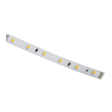
Each Auragami®Light Sheet package includes one sheet (A), two short wires (B),
two long wires (C) and eight bumpers (D).
SAFETY INFORMATION
Read all installation instructions before beginning.
// Toreducetheriskofre,electricshockorinjurytopersons,paycloseattentiontothismanualandstaywithinitsguidelineswhenusingthis
product. Save these instructions for future use. READ AND FOLLOW THE PRODUCT HANDLING, INSTALLATION & INTEGRATION ADVISORY
ON PAGE 4. DISCONNECT POWER AT THE SOURCE BEFORE CUTTING OR ALTERING THE LIGHT SHEET(S) IN ANY WAY. DO NOT CONNECT
LIGHT SHEETS TO AC CURRENT. USE ONLY WITH 24V DC INPUT POWER.
// Products should be installed in accordance with these instructions, current local/regional electrical codes and/or the current National Electric
Code (NEC).
// Use only with UL Listed or UL Recognized Class 2, Limited Power Source (LPS) or LVLE (Low Voltage Limited Energy) power supplies. Provide the
appropriate number of 24V Class 2 circuits for your layout. Do not exceed the maximum load limit of any power supply per the manufacturer’s
recommendations.
//ToretainClass2complianceperULregulations,donotinterconnectmorethaneightfullLightSheets(88wattstotal)inanyconguration.
EachLightSheetconsumes11wattsofpower(0.46Aat24VDC).InordertoconnecteightLightSheets,conrmthatthecombinedpower
consumption is never more than 88 watts total. The Light Sheet’s FPC (Flexible Printed Circuit) design and integrated connection blocks have a
96W/4Aat24VDCcapacity.DonotexceedthecapacityoftheFPCandconnectionsblocksinanyconguration.
// This product is rated IP65 and can be used in wet locations, but not where water may accumulate.
// When using any type of mechanical fastener, make sure the fastener head does not penetrate the Auragami Light Sheet. Any penetrations of the
Light Sheet must be made inside the smaller of the two concentric circles marked on the sheet.
PART DESCRIPTION QTY
AAuragami®Light Sheet (19.80” x 9.25” / 503.5 mm x 235 mm) with
3M®adhesive backing and 12 integrated connection blocks 1
PART ACCESSORY PACK (INCLUDED: AG1-24-RGBW-AP) QTY
B20 AWG short sheet-to-sheet connection wires 3.26” (83 mm) 2
C20 AWG long sheet-to-sheet connection wires 5.86” (149 mm) 2
DProtective bumpers with silicone adhesive backing 8
A B
C
D
AURAGAMI®LIGHT SHEET
SHORT SHEET-TO-SHEET
CONNECTION WIRES
LONG SHEET-TO-SHEET
CONNECTION WIRES
* Not to Scale
PROFILES
Each bumper
can support
up to 400 lbs
(199kg)
Bumper with silicone
adhesive backing
Integrated 5-pin connection
block (TYP. of 12)
RGBW LIGHT SHEETS
0.35” (9mm)
(when bearing
weight)
including Light
Sheet thickness
3/8” Nominal
0.25”
(6.5mm)
including
Light Sheet
thickness
1/4” Nominal
BEST PRACTICES
Do not set anything on top of Light Sheets (i.e. tools, mugs, etc.).
DonotsetLightSheetsontheoorwheretheycouldbestepped
upon or where anything can be dragged or set upon them. Light
Sheets can be damaged unless properly handled.
Due to possible unforeseen issues with shipping and handling,
we advise that all Light Sheets be inspected at time of delivery
anddry-ttestedforproperilluminationpriortomountingand
again before the forward facing material is installed.
For troubleshooting guidance, please visit www.evo-lite.com
FLEXIBLE LED LIGHT SHEET | RGBW
ITEM #: AG1-24-RGBW SERIES (RED, GREEN, BLUE, WHITE)
INSTRUCTION MANUAL
BACKLIGHTING // LED SHEETS // AURAGAMI®// RGBW
SPECIFICATIONS SUBJECT TO CHANGE WITHOUT NOTIFICATION
PHYSICAL
Cut/Fold Line
Spacing 0.99” (25.18 mm) short axis / 0.925” (23.5 mm) long axis
Coverage 1.27 ft20(.118 m2) per sheet / up to 10.18 ft2(0.94 m2)
per Class 2 guidelines
Operang Temp. -30˚C(-22˚F)~+50°C(+122°F)
POWER & CONTROLS
Compable with full range (100% - 0%), icker-free power and control components.
Please contact Evo-Lite for opmal soluons to t your requirements.
ELECTRICAL
Input Voltage 24 Volt DC - Constant Voltage
Input Power 11 W per sheet
Connecvity Up to eight sheets via integrated connection blocks (not to exceed 88 W)
Cercaon ULListed(E495221),CECompliant(EMCandLVD),RoHSCertied,IP65
SPECIFICATIONS
24V
IP65
RoHS
COMPLIANT
DIMMABLE
+−
83 mm (3.26”)
PROTECTIVE BUMPERS
9 mm
(0.35”)
12.8 mm (0.50”)
149 mm (5.86”)
WWW.EVO-LITE.COM • [email protected] • 1-888-887-2980 • ©2020 EVO-LITE, LLC • 6240 W 54TH AVE., ARVADA, CO 80002 • V2–3220
AURAGAMI® DRY FITTING, CUTTING* AND FOLDING
DrytthesheetsandconnectionwiresbeforemountingtheLightSheetstothesubstrate.Always test function before installing the translucent (forward
facing) material.
To make a fold in an Auragami Light Sheet, bend the sheet along one of the dotted lines marked on the sheet, then crease along this line, then relax the
foldintoa90°(orotherdesired)angle.Be careful about folding where an LED is attached to the sheet since LEDs can break if forced over an edge. Do not
repeatedly fold and unfold along the same line as this will weaken the exible PCB. Do not fold a Light Sheet back onto itself, however two separate Light
Sheets can be attached back-to-back.
To make a cut in an Auragami Light Sheet, use shears, scissors, a utility knife and/or a precision/craft knife.
Cut on horizontal and/or vertical lines. Deviating from the lines could cut o power to one of more LEDs.
If a cut edge has the possibility of making contact with a conductive surface or another cut edge, cover the cut
edge with RTV sealant or conformal coating. If one or more connection blocks exist on a cut/fold line, it is best
to remove the connection block* to make a clean fold or cut. Using a pair of slip-joint pliers, grasp the connection
blockrmly(frontsidetobackasillustratedatright)androtateiteitherclockwiseorcounterclockwisewhile
holding the Light Sheet in place. The connection block will unseat from the solder. Repeat for other connection
blocks as needed and discard the removed block(s).
Short sheet-to-sheet connectors (B): When adjacent Auragami Light Sheets are mounted side-by-side with connection blocks aligned, the shorter
sheet-to-sheet connection wires (B) should be used to interconnect multiple sheets. Their lengths are optimized so sheets align snugly. See Figure 1.
WhenconnectingLightSheetsthatarealreadymountedtoaxedsurface,theshortconnectionwires(B)willneedtobeshapedasshowninFigure
2 prior to pushing into connection blocks.
Best practices include using two sheet-to-sheet connection wires for all adjacent Light Sheets in each Class 2
circuittominimizevoltagedrop.Dry-ttestforproperilluminationpriortomountingLightSheetstothemountingsurfaceandagainbeforetheforward
facing material is installed.
USING AURAGAMI®ACCESSORIES
Figure 1 Figure 2 Figure 3
OR
*NEVER CUT OR ALTER LIGHT
SHEET(S) WHILE POWERED.
Long sheet-to-sheet connectors (C):
Usethelongsheet-to-sheetconnectionwires(C)tobridgegapsand/orconnectosetsheetsas
shown in Figure 3.
Domed protective bumpers (D):
Rated for 400 lbs each, the domed protective bumpers (D) included with each Light Sheet have
been engineered to bear the weight of translucent materials in horizontal applications and act
as a safeguard in vertical applications so that the forward facing material does not harm the
Light Sheet’s integrated connection blocks or LEDs. Evo-Lite recommends using eight bumpers
per Light Sheet (approximately six per square foot), spacing them evenly to distribute the weight
of the forward facing material (see Figure 4) and to add a level of protection in vertical applications
when the forward facing material will be positioned near the Light Sheet (see Figure 5). A rigid,
non deforming mounting surface/substrate must be used with any weight bearing applications to
avoid damaging the Auragami Light Sheet.
Cable management clips (G) (included in the power input kit sold separately):
Route the connection wires so that the light from the LEDs is not blocked and hold the wires in this
position using cable management clips with silicone adhesive backing (G) as shown in Figure 3.
Once applied, let this adhesive backing cure for 10-30 minutes before routing wires through the
clip. When possible, use a mechanical fastener to secure the clip.
B
B
C
Integrated 5-pin
connection block
Translucent (Forward Facing) Material
D
B C D G
SHORT SHEET-TO-SHEET CONNECTION WIRES LONG SHEET-TO-SHEET CONNECTION WIRES PROTECTIVE BUMPERS
G
G
Translucent
(Forward Facing)
Material
Integrated 5-pin
connection block
D
Figure 5
Figure 4
CABLE MANAGEMENT CLIPS
8.85 mm
(0.35”)
10 mm
(0.39”)
9 mm
(0.35”)
12.8 mm (0.50”)83 mm (3.26”) 149 mm (5.86”)
31 mm (1.22”)
WWW.EVO-LITE.COM • [email protected] • 1-888-887-2980 • ©2020 EVO-LITE, LLC • 6240 W 54TH AVE., ARVADA, CO 80002 • V2–3220
LIGHT SHEET ORIENTATION
RGBW and Tunable White Auragami Light Sheets have arrows printed on them. These
arrows mark the direction and orientation that all sheets must be installed. When mounting
multiple sheets, it is important that the arrows on each sheet line up and point the same
direction. These arrows help maintain equal LED spacing. If the arrows are not aligned, you
may experience color shifts or hot spots. See Figure 8.
MOUNTING LIGHT SHEETS
VariousmountingmethodsmaybeusedtosecuretheLightSheetstothemountingsurfaceafterthedry-tandoperationtestsarecomplete.
Use the appropriate method or combination of methods depending on the type of mounting surface and its orientation. Mechanical fastening is
recommended in addition to the adhesive back.
Mechanical Fasteners: Any penetrations through the Light Sheet must be made inside the concentric circles marked on the sheet. The smaller
diameter circle on the Light Sheet indicates the maximum diameter of screw or other fastener that can be used without causing damage to the
Light Sheet’s power distribution grid. The larger diameter circle is the maximum diameter of the screw head that can be used without causing
damage. See Figure 9. For suspended applications, use mechanical fasteners with an appropriate spacing to avoid sagging. Use pan head, domed,
or round head screws
–
not tapered screws (like wood or drywall screws)
nor self-tapping screws –
and never screw the fastener so much that it
deforms the Light Sheet. See Figure 10.
Re-test function before installing the translucent (forward facing) material.
0.24”
(6 mm)
0.12”
(3 mm)
Figure 9
Figure 8
Figure 10
POWER INPUT
Use only with Class 2 power units. To avoid visible brightness variances due to voltage drop, the total distance should not exceed 6.5 ft (2 meters)
from the Light Sheet’s power supply input to the farthest end of any interconnected sheet. If this distance exceeds 6.5 ft (2 meters), splice an
additional high count multi-strand lead wire (that is the appropriate gauge for the load and distance) to the power input wire and connect this lead
to a sheet that is centrally located within the interconnected sheets. Alternatively, split the length in two and power each with its own power supply,
making sure the two sections are not connected electrically (see Figure 6).
Use the power lead (E) to route power from the power supply to a single Light Sheet or a set of up to eight Light Sheets. Use
Wago connectors (F)
inplaceofwirenuts,forasecureconnectionofwiresofthesamepolarity(seegure7).Donotexceedthe4Amaximumloadcapacityofa
connectionblockinanycongurationnorinterconnectmorethaneightsheets(88Wtotal).IfanyLightSheetfailstolight,checkthatthesheet-to-
sheet connection wires are fully connected into the 5-pin connection blocks. If the whole layout fails to light, check polarity at the power supply,
proper connection at the splicing connectors, and supply power at the source.
Light Sheets are dimmable, compatible with full-range (100% - 0%), icker-free power and control components. Barrel connectivity options/
accessories are sold separately for use with barrel connected plug-in power supplies. Contact an Evo-Lite Systems Integration Specialist for optimal
powerandcontrolsolutionstottheprojectneeds.
Power Input Kit, SKU: AG1-24-RGBW-PIK (sold separately):
Includes one 48” (1219.2 mm) 20 AWG 5-conductor power lead
wirewithstripped&tinnedends(E),veWagoconnectors(F)(see
Figure 7) and four cable management clips (G) (see Figure 3).
Figure 7
E F
G
POWER INPUT CABLE WAGO CONNECTORS
* Not to Scale
+
–
Multi-Channel Control Component
(24V DC Output sold separately)
B
G
R
W
x5
Note: The black wire is positive (+)
and the other colored wires (RGBW)
are signal (-) control wires.
F
E
G
–
–
–
One power input is required for each Class 2 circuit
Figure 6
221
221
221
221
221
CABLE MANAGEMENT CLIPS
WWW.EVO-LITE.COM • [email protected] • 1-888-887-2980 • ©2020 EVO-LITE, LLC • 6240 W 54TH AVE., ARVADA, CO 80002 • V2–3220
TEST BEFORE
INSTALLING
Our production, packaging and shipping process is accompanied by a rigorous quality control procedure.
All Auragami Light Sheets are subjected to a burn in period and are tested before packaging to ensure
operation of the highest quality. Due to possible unforeseen issues with shipping and handling, we
advisethatallLightSheetsbeinspectedattimeofdeliveryanddry-ttestedforproperillumination
prior to mounting and again before the forward facing material is installed.
FRAGILE 5-PIN
CONNECTION
BLOCKS
DISCONNECT POWER AT THE SOURCE BEFORE REMOVING ANY CONNECTION BLOCKS.
The Light
Sheet’s integrated 5-pin connection blocks are made of plastic which can be damaged if made to bear weight.
Use domed protective bumpers (included) to bear the weight of any forward facing material in horizontal
applications and to act as a safeguard to protect the Light Sheet in vertical applications.
DRILLING
DISCONNECT POWER AT THE SOURCE BEFORE ALTERING THE SHEET IN ANY WAY. Light Sheets have
specicareaswhereholescanbemadeinthesheet.ThesmallerdiametercirclesontheLightSheet
(0.12” / 3 mm) indicate the maximum diameter of screw or other fastener’s shaft that can be used
without causing damage to the Light Sheet’s power distribution grid. The larger diameter circle (0.24” / 6
mm) is the maximum diameter of the screw head that can be used without causing damage.
PRODUCT HANDLING, INSTALLATION & INTEGRATION ADVISORY
INSTALLATION
TEMPERATURE
Due to the characteristics of the 3M adhesive backing, installation environments and locations should
be taken into consideration. Low temperatures can cause longer cure times for permanent adhesion.
STORAGE Store
Auragami Light Sheets
inaclean,dryareaonaat,horizontalsurface.Donotopentheanti-static
envelopeuntilreadytoinstall.Idealstorageconditions:Temperatureof68°–77°F,50%humidity.
STORAGE
DO NOT CONNECT
TO AC POWER
ANY DIRECT CONNECTION OF AURAGAMI LIGHT SHEETS TO AC CURRENT WILL DAMAGE THE LEDs.
Be sure to use a UL Listed or UL Recognized Class 2, LPS or LVLE low voltage power supply that conforms
to the voltage requirements of the Light Sheet. This information can be found on the Auragami Light
Sheet and its packaging, as well as the power supply labeling.
Evo-Lite’s experience in providing backlighting solutions yields a unique perspective on the characteristics and underlying intuitive knowledge necessary to complete a
successful installation of Auragami. Evo-Lite is committed to educating and supporting all our customers so every installation proceeds as smoothly as possible. Most
installationsoertheirownuniquechallenges;wehopebymakingyouawareofthefollowinghandlingandinstallationguidelinesyouareempoweredwithknowledge
forasuccessfulinstallation.Asalways,yourEvo-LiteSystemsIntegrationSpecialistoranyofourstaarereadytoassistyouwithanyquestionsthatariseduringyour
installation.
FOLDING &
MINIMUM RADIUS
There is no minimum bending radius for Auragami Light Sheets, however a single sheet may not be
foldedonitselfbecausethiscoulddisrupttheowofelectricitythroughthefoldedsheet.Twoseparate
IP65 sheets may be attached back-to-back since the 3M adhesive backing will act as non-conductive
barrier. Light Sheets are not recommended for applications where a radius of less than 2” exists.
CUTTING
DISCONNECT POWER AT THE SOURCE BEFORE ALTERING THE SHEET IN ANY WAY. NEVER CUT
AURAGAMI LIGHT SHEET WHILE POWERED. Field cutting of the Light Sheet does not void UL Listing. LEDs
can lose input power if cut lines are not followed. Avoid cut edge contact with any conductive material(s),
including other cut edges of Light Sheets. See also Wet Location Use below.
SOLDERING
DISCONNECT POWER AT THE SOURCE BEFORE ALTERING THE SHEET IN ANY WAY. Solder sheets or
strips of Auragami together or solder power input(s) to Light Sheets. The Light Sheet’s copper pads are
engineeredtohandle4Aofloadandpolarityisnotedbythe+and-nexttoeachcopperpad.Use20
AWG stranded copper wire for up to 4 A of load and follow electronics soldering best practices.
FASTENING
USE PAN HEAD, DOMED, OR ROUND HEAD FASTENERS, NOT TAPERED SCREWS. Never screw the
fastener so much that it deforms the Light Sheet. Only penetrate the Light Sheet within the smallest
of the two concentric circles marked on the sheet (see Drilling above for screw size limitations). For
suspended applications, use mechanical fasteners with an appropriate spacing to avoid sagging.
WET LOCATION
USE
Auragami Light Sheets are rated IP65. This rating is total protection against dust ingress as well as water
projected by a nozzle against the enclosure from any direction for a limited time and may be used in wet
locations, but not where standing water can accumulate. Cut edges of IP65 can optionally be sealed from
moisture with an RTV Silicone Sealant or conformal coating.
IP65
POWER, CONTROL
& WIRING
For optimal power distribution and to minimize voltage drop, it is recommended that multi-strand, high
strand count wiring be used for all low voltage DC connections. Wire gauge should be appropriate based
uponsystemvoltageandwirelengthstofurtherminimizevoltagedrop.Powersupplies,driversand
controls should be installed in well ventilated enclosures and/or per manufacturers recommendations.
It is the customer’s responsibility to ensure all components and installation practices meet or exceed
local codes and requirements.
Auragami® is a patented product of Evo-Lite, LLC. For more information please visit www.evo-lite.com/patent

Other Evo-lite Light Fixture manuals

Evo-lite Auragami AG1-24-TW User manual

Evo-lite

Evo-lite Auragami AG1-24-TW User manual

Evo-lite LUXX 1010 NEON User manual

Evo-lite

Evo-lite LUXX 1010 NEON User manual

Evo-lite HYBRID 360 CMY User manual

Evo-lite

Evo-lite HYBRID 360 CMY User manual

Evo-lite MaxBAR 180 User manual

Evo-lite

Evo-lite MaxBAR 180 User manual

Evo-lite M2000 User manual

Evo-lite

Evo-lite M2000 User manual

Evo-lite EVOWASH1240Z-R User manual

Evo-lite

Evo-lite EVOWASH1240Z-R User manual

Evo-lite Evo Spot 120 User manual

Evo-lite

Evo-lite Evo Spot 120 User manual

Evo-lite Air Beam 60 User manual

Evo-lite

Evo-lite Air Beam 60 User manual

Evo-lite MOVING BEAM 5R User manual

Evo-lite

Evo-lite MOVING BEAM 5R User manual

Evo-lite EVO Wash 610-CRz User manual

Evo-lite

Evo-lite EVO Wash 610-CRz User manual

Evo-lite MaxBAR 210 IP65 User manual

Evo-lite

Evo-lite MaxBAR 210 IP65 User manual

Evo-lite Evo Spot 180 User manual

Evo-lite

Evo-lite Evo Spot 180 User manual

Popular Light Fixture manuals by other brands

ABB Stanilite installation manual

ABB

ABB Stanilite installation manual

Raytec VARIO2 i16 Quick start up guide

Raytec

Raytec VARIO2 i16 Quick start up guide

ACME Xperior 5R BEAM F user guide

ACME

ACME Xperior 5R BEAM F user guide

Muller licht 57016 manual

Muller licht

Muller licht 57016 manual

DTS XR8 SPOT user manual

DTS

DTS XR8 SPOT user manual

Cameo CLMHRGB60W user manual

Cameo

Cameo CLMHRGB60W user manual

JB Systems FL30-WW-SET-3528-3M Operation manual

JB Systems

JB Systems FL30-WW-SET-3528-3M Operation manual

Triarch 25763 instructions

Triarch

Triarch 25763 instructions

Eternal Lighting Cube RGBA user manual

Eternal Lighting

Eternal Lighting Cube RGBA user manual

Triarch 29320/2 Assembly instruction

Triarch

Triarch 29320/2 Assembly instruction

Quoizel MLO8409WT installation guide

Quoizel

Quoizel MLO8409WT installation guide

Cooper Lighting Sure-Lites CU-1-R Series Specifications

Cooper Lighting

Cooper Lighting Sure-Lites CU-1-R Series Specifications

Emos NANO CLUSTER manual

Emos

Emos NANO CLUSTER manual

Cooper Lighting Ametrix ADY071481 installation instructions

Cooper Lighting

Cooper Lighting Ametrix ADY071481 installation instructions

Westfalia Wetelux 91 96 03 Original instructions

Westfalia

Westfalia Wetelux 91 96 03 Original instructions

Philips 1050DRN specification

Philips

Philips 1050DRN specification

Schrack Technik ILAS LED Series Assembly instructions

Schrack Technik

Schrack Technik ILAS LED Series Assembly instructions

Cooper Lighting SURE-LITES UNH/PLX Specifications

Cooper Lighting

Cooper Lighting SURE-LITES UNH/PLX Specifications

manuals.online logo
manuals.online logoBrands
  • About & Mission
  • Contact us
  • Privacy Policy
  • Terms and Conditions

Copyright 2025 Manuals.Online. All Rights Reserved.