Evolve Power Beam User manual

Power Beam Installation Guide

EVOLVE EVOLVE
evolvefurnituregroup.com • Page 3Page 2 • evolvefurnituregroup.com
NOTE: Any alterations to listed components will void the manu-
facturer’s warranty. The manufacturer will not be responsible for
any damage or bodily harm caused
by alterations in accordance with national or local electrical
codes and manufacturer’s specifications. In accordance with the
manufacturer’s policy of continual product improvement, the
product presented in this document is subject to change without
notice or obligation.24
Please contact your Evolve Service Representative at
856.552.4000 for any questions or concerns.
* These Items are available through customer service at
856.552.4000.
Power Beam
Safety Glasses #2 Phillips Screwdriver
Adjustable 8” Wrench
General Purpose Prybar
1/2” Pan Head Screw
1/2” Pan Head Tapping Screw
Fabric Spline Roller*
5/16” Nut-Driver
Large 1/4” Blade Screwdriver
Tape Measure
Rubber Mallet #3 Phillips Screwdriver
Needlenose Pliers
Power Prill (var speed, rev)
3/8” Nut-Driver
3/16” Diamiter Punch
Gloves
1/2” Wrench
Large Channel Lock Pliers
Magnetic drill bit holders
#2 Robertson Screwdriver
Utility Knife
Metal Pick*
9/16” Wrench
Fine tooth Saw (Hacksaw)
1/4” Nut-Driver
#3 Robertson Screwdriver
48” Long Level
Required Tools Additional items you may find useful:
Screws Used During Installation
Power Beam Assembly
Electrics
Corner Posts
Over Panels
Laminate Gallery Panels
Storage Cabinets
Felt Dividers
Privacy Glass
4
5
6
7
8
8
9
10
TABLE OF CONTENTS INSTALLATION GUIDELINES
EVOLVE EVOLVE
evolvefurnituregroup.com • Page 5Page 4 • evolvefurnituregroup.com
INSTALLATION GUIDELINES INSTALLATION GUIDELINES
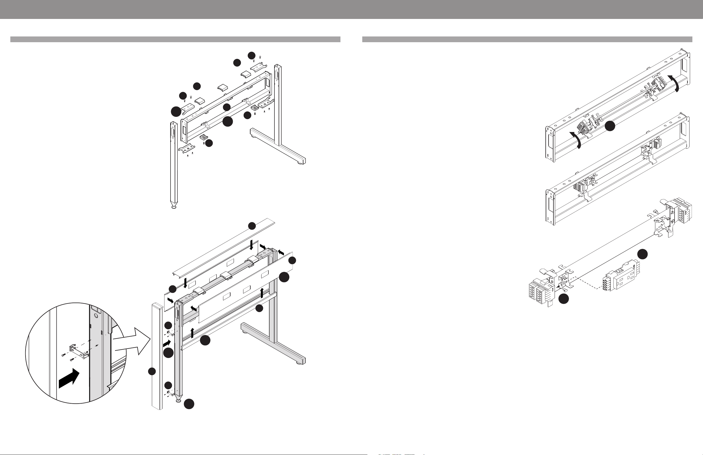
Power Beam
STEP 1: Connect the power beam (a) to the connectors using
four clamps (b).
Two at the bottom, two at the top.
STEP 2: Attach the plastic blocks (c) to the bottom, and the
spacers (d) to the top of the power beam. *The plastic blocks (c)
are to be attached with screws, while the spacers (d) come with
an adhesive.
STEP 3: Add a raceway cover (e) on either side of the power
beam.
STEP 4: Install bottom trim (f) and top trim (g).
STEP 5: Install the spring clips (h) using the supplied self drilling
screws and snap on the end trims (i).
STEP 6: Adjust levelers as needed.
1
a
e
e
i
c
c
g
b
b
d
d
f
h
h
2
3
5
6
4
Power Beam - Electrics
Power Distribution Housing
STEP 1: Insert the power distribution housing at an angle with
the tabs facing down, into the corresponding slots. Push it in
until it clicks.
STEP 2: Position the receptacle into the mounting bracket on the
power distribution housing. There is an arrow and letter “N” to
indicate which way is up.
STEP 3: Slide it towards the assembly connectors. Be sure the
parts are fully seated to assure proper electrical connection and
the spring clips are properly engaged for mechanical security.
1
2
3
EVOLVE EVOLVE
evolvefurnituregroup.com • Page 7Page 6 • evolvefurnituregroup.com
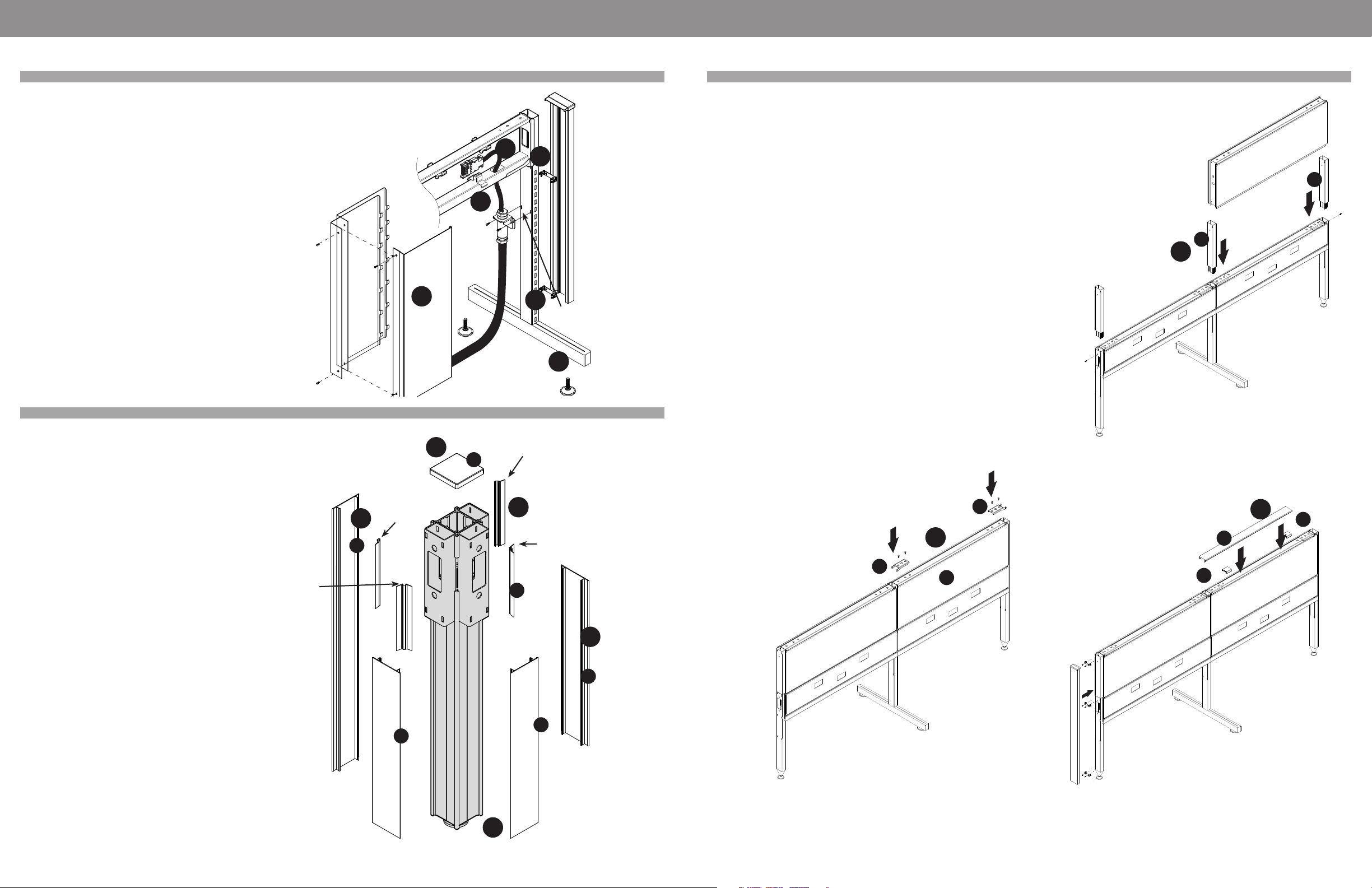
Power Beam - Corner Post
Power Beam - Electrics
STEP 1: Install the long flat trims (a) by snapping them on the
exposed sides of
the post.
STEP 2: Snap on the shorter flat trims (b) on the post, below the
power beam.
STEP 3: Press in the PVC slot covers (c) between the connectors.
Tear o the
flexible side of the PVC slot cover when inserting it between the
long trim and
the connector.
STEP 4: Install the post top cap (d).
STEP 5: Adjust the leveler as needed.
Base Feed and Base Feed Cover
STEP 1: Base feed bracket attaches to leg with provided screws.
STEP 2: Run the flexible portion of the feed through the opening
in the bottom of the power beam.
STEP 3: Add the base feed cover and secure it using the two
provided screws.
STEP 4: Snap on two spring clips to accept the end trim with
end cap.
STEP 5: Adjust levelers as needed.
Note: There must be only one power feed entry into each cluster
of stations.
Connection to the building supply must be done only by a
licensed electrician,
and in accordance with applicable codes and regulations.
Do not connect or disconnect components while the system is
under load!
Disconnect the main power before servicing or reconfiguration.
Slots for Base
Feed bracket
13
2
2
3
1
4
4
5
4
5
a
c
b
b
b
d
Tear o
flexible side
Tear o
flexible side
Do not tear o
flexible side
Do not tear o
flexible side
INSTALLATION GUIDELINES INSTALLATION GUIDELINES
Power Beam - Over Panels (Extension Modules)
*Remove or do not install the plastic spacers (d). Remove or do
not install the top trim yet (e).
STEP 1: Insert the extension connector (a) and secure it in place
using the provided screw. Post extensions work the same way.
STEP 2: Slide in the module (b) and attach it to the extension
connectors using the clamps (c).
STEP 3: Add two plastic spacers (d) on top and snap on the top
trim (e).
1
2
3
a
a
c
d
d
e
c
b

EVOLVE EVOLVE
evolvefurnituregroup.com • Page 9Page 8 • evolvefurnituregroup.com
INSTALLATION GUIDELINES INSTALLATION GUIDELINES
Power Beam - Part Description
Part Description
1 - Laminate end Power
2 - Connector with leg
3 - Attachment Bracket
4 - Wood Screws
5 - End-of-Run Trim
6 - Cap
7 - Spring Clip
8 - Self Drilling Screw
Note: First attach power beam to legs, level it and then start installing
laminate end panel. Fasten spring clip to leg with screws (8) to hold end-of-
run trim (5).
STEP 1: Assemble Power Beam with legs and level it
STEP 2: Attach spring clips to leg with provided self drilling screws and snap on trim
STEP 3: Place brackets in leg groove at leg ends
STEP 4: Put laminate end panel against trim, center and level laminate panel
STEP 5: Mark location of trim with pencil on laminate panel
STEP 6: Take o trim and drill holes in trim on center then place trim at marked
location and trill pilot holes in laminate panel, attach trim with wood screws
STEP 7: Place laminate panel with with attached trim against leg until trim
snaps on
STEP 8: Drill pilot holes for bracket and attach it with wood screws
STEP 9: Make sure that laminate panel is secure
Note: Trim must be attached to laminate panel and snapped on spring clips
secured with screws to leg.
Part Description
1 - Top Trim
2 - Power Beam Open Storage Cabinet
3 - Leveler x2
4 - Attachment Bracket
5 - Screw for Attachment Bracket
6 - Dual Access Overhead
7 - Bracket for Overhead
8 - Wood Screw to attach Overhead
9 - Power Beam at 24”H
10 - 36”H Inline Connector with Leg
11 - Bottom Horizontal Tube with Cut Out
12 - Clamp
13 - Screw
14 - Bottom Trim for Top Horizontal Tube
15 - PVC Spacer
16 - Double Notched Top Trim
17 - End-of-Run Trim
18 - Spring Clip
19 - Self Drilling Screw
20 - Top Horizonal Tube
21 - Electric Cover
INSTALLATION GUIDELINES
Power Beam - Storage Cabinet Instructions
Felt Dividers
STEP 1: Place Blocks (4) into position
STEP 2: Remove strips o of tape underneath 12” Spacer Clip
(3) and locate in middle of panel
STEP 3: Align felt evenly within the channel
STEP 4: Push felt down firmly and evenly into the channel.
1
2
4
3

EVOLVE EVOLVE
evolvefurnituregroup.com • Page 11Page 10 • evolvefurnituregroup.com
Privacy Glass installation with new seals
Parts List
1 Glass
2 Aluminum Top Trim with channel
3 12” Spacer Clip
4 Block
5 Glass Seal
6 End Cap
7 Small Glass Seal in middle
A Wall Mount is the same as an End-of-Run
Post Kit. It is used to attach a panel run to a
fixed wall.
STEP 1: Remove strips o of tape under-
neath 12” Spacer Clip (#3) and locate in
middle of panel.
STEP 2: Remove existing pan head screws
just outside the single panel clamps, from
the top horizontal rail. Place Blocks (#4)
into position
over screw hole and secure using the same
screw previously removed.
STEP 3: Position Top Trim (#2) so the ends
of trim align with the center of the connec-
tor slots. The holes in the channel that holds
the glass,
should align with the screws holding the
blocks below. Snap top trim on securely.
a. Note: To remove the Top Trim, the
screws in the blocks below must be loos-
ened first. After removing the Top Trim, the
blocks can be slid to the side, to remove and
reuse.
STEP 4:Place the Seal (#5) over each hole,
and seal (#7) in middle, in the Top Trim
extrusion channel, symmetrically so the
cutouts align with the top of the extrusion
channel, and the same amount sticks above
the extrusion on each side.
STEP 5: Align glass evenly within the chan-
nel.
STEP 6: Push Privacy Glass down firmly and
evenly into the channel.
STEP 7: Using an exacto knife, cut the ex-
cess material on the Seal (#5) that is stick-
ing up above the channel.
STEP 8: Push Cap(#6) in top tim channel at
ends to close open ends, see details
INSTALLATION GUIDELINES
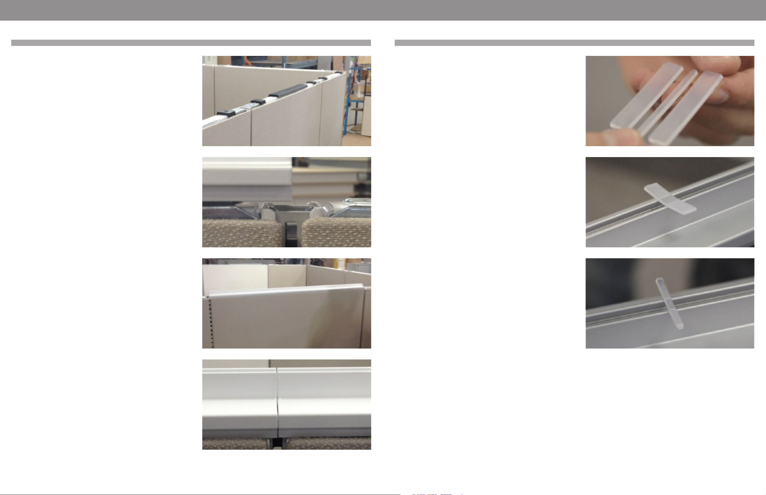
Privacy Glass Installation Instructions
STEP 1: Remove screw
STEP 2: Install block and screw back using the same screw. It is
important to start the installation from the middle panel.
STEP 3: Blocks installed
STEP 4: Peel o double sided tape
INSTALLATION GUIDELINES
EVOLVE EVOLVE
evolvefurnituregroup.com • Page 13Page 12 • evolvefurnituregroup.com
STEP 5: Install PVC spacer in the middle
STEP 6: Locate top trim and adjust sideways to the middle of the
slot
STEP 7: Snap on block
STEP 8: Install next top trim while ensuring that both trims are fully
aligned
INSTALLATION GUIDELINES
Privacy Glass Installation Instructions Privacy Glass Installation Instructions
STEP 9: Plastic seal with grooves on the top side. For ease of
installation, use 1/2” plastic seal.
STEP 10: Plast plastic seal on the head of the block screw with
grooves facing down. Adjust the plastic seal symmetrically on the
top of the trim on both sides.
STEP 11: Place thin seal in middle of trim
INSTALLATION GUIDELINES

EVOLVE EVOLVE
evolvefurnituregroup.com • Page 15Page 14 • evolvefurnituregroup.com
STEP 12: Hold privacy glass from both ends (2 people) and install
privacy glass ensuring that the glass seal is fully aligned.
STEP 13: If glass seal slides o place, pull glass up and re-install as
indicated in the previous step.
STEP 14: Logo should always be consistently on the same bottom
corner. Ensure consistency with having the shiny sides of the
privacy glass on the same side.
INSTALLATION GUIDELINES
Privacy Glass Installation Instructions Privacy Glass Installation Instructions
STEP 15: Ensure that the 2 adjacent privacy glass pieces are aligned
and a tight gap is left between the 2 edges (3/32”)
STEP 16: Installation of privacy glass is complete with shiny side out
and logo on the bottom left corner
INSTALLATION GUIDELINES

EVOLVE EVOLVE
evolvefurnituregroup.com • Page 17Page 16 • evolvefurnituregroup.com
STEP 17: Check the squareness of glass
STEP 18: If needed, pull in the opposite direction and check again
STEP 19: When installation is fully satisfactory, cut protruding
plastic seal with exacty knife
INSTALLATION GUIDELINES
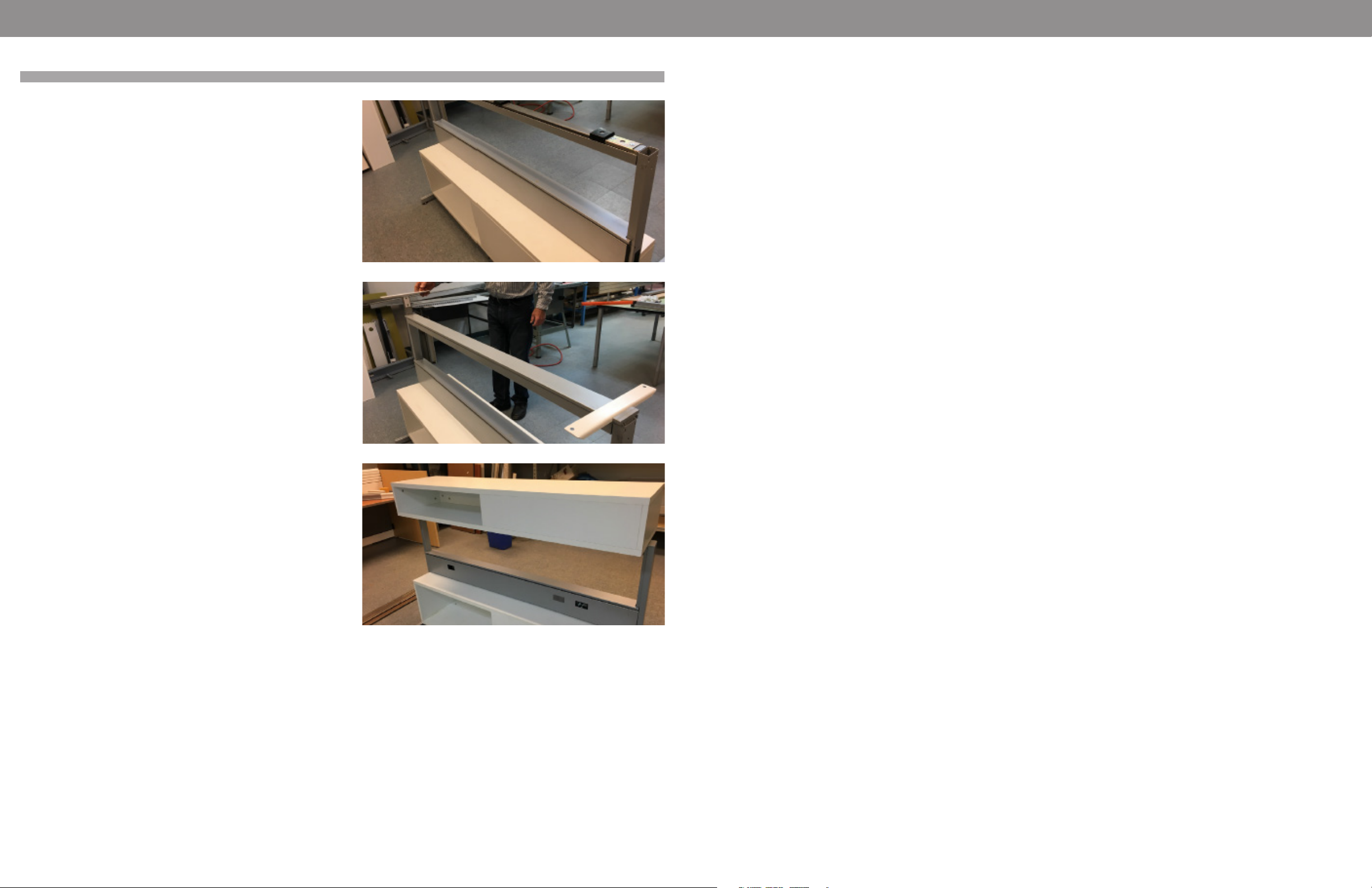
Privacy Glass Installation Instructions Power Beam Storage Cabinet Instructions
STEP 1: Assemble Power Beam with legs and level it, place two
connectors flat
STEP 2: Install Glides, turn in until glides are lower than connector
STEP 3: Place storage cabinet on laying connectors between legs
and slide under Power Beam
INSTALLATION GUIDELINES

EVOLVE EVOLVE
evolvefurnituregroup.com • Page 19Page 18 • evolvefurnituregroup.com
STEP 4: Storage Cabinet under Power Beam
STEP 5: Lift one end of cabinet and rotate connector to sit on
narrow side on floor. repeat on other end
STEP 6: Cut out in top under Power Beam bottom tube
INSTALLATION GUIDELINES
Privacy Glass Installation Instructions Power Beam Storage Cabinet Instructions
STEP 7: Attach provided bracket with screw in threaded insert
outside clamp
STEP 8: Use power drill to fasten bracket with screw lifting storage
cabinet until gable touches bottom tube
STEP 9: Extend glides to support cabinet and level cabinet
INSTALLATION GUIDELINES
EVOLVE EVOLVE
evolvefurnituregroup.com • Page 21Page 20 • evolvefurnituregroup.com
STEP 10: For overhead install top horizontal tube with bottom trim
STEP 11: Install top trim and brackets
STEP 12: Attach overhead with provided screws to brackets
INSTALLATION GUIDELINES
Privacy Glass Installation Instructions

EVOLVE
Page 22 • evolvefurnituregroup.com
power beam installation guide
Global - USA Headquarters
17 West Stow Road P.O. Box 562
Marlton, New Jersey U.S.A. 08053
Tel (856) 596-3390 (800) 220-1900
Fax (856) 596-5684
www.globalfurnituregroup.com
Global - Canada Headquarters
1350 Flint Road
Downsview, ON Canada M3J 2J7
Sales & Marketing: Tel (1-877) 446-2251
Customer Service: Fax (800) 361-3182
Government Customer Service: Fax (416) 739-6319
showrooms and distribution centers throughout the united states
Atlanta Area
2124 Evergreen Blvd.
Duluth, GA 30096
T 678.602.4130
F 678.602.4136
Baltimore Area
Troy Hill Corporate
Center
7030 Troy Hill Drive
Elkridge, MD 21075
T 410.379.8021
F 301.362.9444
Boston Area
19 Connector Rd., Unit 1
Andover, MA 01810
T 978.470.8463
F 978.470.8920
Cincinnati Area
8712 LeSaint Drive
Fairfield, OH 45014
T 513.777.0009
F 513.777.5863
Dallas Area
2025 W. Beltline Rd.,
#100
Carrollton, TX 75006
T 972.236.1366
F 972.236.1372
Denver Area
16401 E. 33rd Dr., Ste. 50
Aurora, CO 80011
T 303.340.1617
F 303.340.1657
Ft. Lauderdale Area
560 Sawgrass
Corporate Parkway
Sunrise, FL 33325
T 954.846.8888
F 954.846.8110
Houston
7865 Northcourt Road,
Building D, Suite 200
Houston, TX 77040
T 713.695.5777
F 713.695.5778
Los Angeles Area
12320 Bloomfield
Avenue, Unit A
Santa Fe Springs, CA
90670
T 562.484.9686
F 562.484.9685
New Orleans Area
901 South Labarre
Road, Suite 201
Metairie, LA 70001
T 504.834.6228
F 504.835.9638
San Francisco Area
44091 Nobel Drive
Fremont, CA 94538
T 510.897.4150
F 510.897.4156
Seattle Area
Oakesdale Commerce
Center
820 Southwest 34th St.
Building W7, Suite A
Renton, WA 98057
T 425.291.9282
F 425.291.9287
Kansas Area
11617 West 81st Street
Lenexa, KS 66214
T 913.310.9963
F 913.310.9976
Tampa Area
10351 Windhorst Road
Tampa, FL 33619
T 813.621.6272
F 813.621.7958
Atlanta
10 10th Street, Suite 150
Atlanta, GA 30309
T 404.879.0998
F 404.879.9995
Boston
One Harbor Street,
Suite 104
Boston, MA 02210
T 617.406.5435
F 617.406.5438
Chicago
The Merchandise Mart
10th Floor, Suite 1035
Chicago, IL 60654
T 312.755.0843
F 312.755.0837
Ft. Lauderdale
Las Olas City Centre
401 East Las Olas Blvd.,
Suite 230
Ft. Lauderdale, FL 33301
T 954.763.2684
F 954.763.6870
New York City
386 Park Avenue South,
7th floor
New York, NY 10016
T 212.545.9900
F 212.545.5826
Philadelphia
1735 Market Street
38th Floor
Philadelphia
PA, 19103
(215) 861-0963
New Jersey (Southern)
119 Greentree Road
Marlton, NJ 08053
T 856.596.3390
F 856.596.4472
Phoenix
4675 East Cotton
Center Boulevard,
Suite 165
Phoenix, AZ 85040
T 602.426.0666
F 602.426.1148
St. Louis
5 Document Drive
St. Louis, MO 63114
T 314.432.4463
F 314.432.4471
Washington, DC
1130 Connecticut
Avenue
Washington, DC 20036
T 202.659.0230
F 202.659.0306
SHOWROOMS + DISTRIBUTION CENTERS
SHOWROOMS
Other manuals for Power Beam
1
Other Evolve Office Equipment manuals


Popular Office Equipment manuals by other brands


Worky
Worky THO-01 instruction manual

Herman Miller
Herman Miller 1BKTM2-A installation instructions

Herman Miller
Herman Miller Canvas Office Landscape Installation and Disassembly for Recycling Instructions

Rhin-O-Tuff
Rhin-O-Tuff HD7700 Setup & operator manual

Reiner
Reiner DN41A operating instructions

bbf
bbf A173951A Assembly instructions


