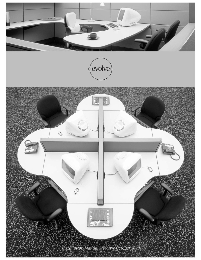
Evolve SHOWROOMS User manual

Evolve Installation Guide

EVOLVE
Page 2 • evolvefurnituregroup.com
NOTE: Any alterations to listed components will void the manu-
facturer’s warranty. The manufacturer will not be responsible for
any damage or bodily harm caused
by alterations in accordance with national or local electrical
codes and manufacturer’s specifications. In accordance with the
manufacturer’s policy of continual product improvement, the
product presented in this document is subject to change without
notice or obligation.24
Please contact your Evolve Service Representative at
856.552.4000 for any questions or concerns.
Corner Connections – Equal Height
Corner Connections – Variable Height
Corner Connections – Corner Post Extension
Inline Connection – Equal Height
Inline Connection – Variable Height
Notched Top Cap
Inline Connection – Panel Extension Module
End-of-Run Post Kit
End-of-Run Post Kit - Wall Mount Application
End-of-Run Post Kit - O Module Application
Felt Dividers
Privacy Glass
Privacy Ceiling
Door Panel
Privacy Screen
Sliding Panel Door Lock
Evolve Panel Removal
Evolve Module Removal
Mobile/Freestanding Monolithic Privacy
Panels
4
5
6
6
7
7
8
9
10
10
11
12
19
20
22
23
24
25
26
38
39
40
41
43
43
44
45
46
46
47
48
49
50
51
53
54
55
56
57
Panels
List of Tools Storage
P.03
P.04
Wiring Schematic
Power Distribution Housing
Jumper Cables and Pass-Through Cables
Reversible Floor Power Entry
Ceiling Power Entry
Duplex Receptacle
Cable Capacity
End Panel
Corner Bracket
Cantilever
Support Leg
Worksurface Supporting Pedestals
Laminate End panels
Optional Accessory Rail
28
28
29
30
31
32
33
34
34
35
35
36
37
37
Electrical
Worksurfaces
P.16
P.22
P.26
TABLE OF CONTENTS
Overhead Flipper Door Storage Unit
Corner Shelf
Low-Profile Shelf
Top Mount Overhead
Panel Mounted Overhead Storage Unit - ADA Compliant
Up-Mount Overhead Storage Unit - ADA Compliant
Up-Mount Conversion Kit
Fine Tuning of Up-Mount Overhead Storage Unit
e-STOR - Two Lateral Cabinet Assembly
e-STOR - Two Lateral Cabinet and Panel Assembly
Storage Cabinets with Pass Through Cables
Double Wall Overhead
Double Wall Overhead Glazed Door
“J” Bars for Double Wall Overhead - Wall Mount
Double Wall Cabinet
O Module Worksurface Bracket
Lock Clip Installation
Pass Thru Sliding Door
Name Plate
Accessory Retainer

EVOLVE
evolvefurnituregroup.com • Page 3
* These Items are available through customer service at
856.552.4000.
Evolve
Safety Glasses #2 Phillips Screwdriver
Adjustable 8” Wrench
General Purpose Prybar
1/2” Pan Head Screw
1/2” Pan Head Tapping Screw
Fabric Spline Roller*
5/16” Nut-Driver
Large 1/4” Blade Screwdriver
Tape Measure
Rubber Mallet #3 Phillips Screwdriver
Needlenose Pliers
Power Prill (var speed, rev)
3/8” Nut-Driver
3/16” Diamiter Punch
Gloves
1/2” Wrench
Large Channel Lock Pliers
Magnetic drill bit holders
#2 Robertson Screwdriver
Utility Knife
Metal Pick*
9/16” Wrench
Fine tooth Saw (Hacksaw)
1/4” Nut-Driver
#3 Robertson Screwdriver
48” Long Level
Required Tools Additional items you may find useful:
Screws Used During Installation
Installation Sequence
Panels
Corner Connections – Equal Height (EVPCPA2, EVPCPA3, EVPCPA4)
Corner Connections – Variable Height (EVPVPA2, EVPVPA3, EVPVPA4)
Corner Connections – Corner Post Extension (EVPCEPA2, EVPCEPA3,
EVPCEPA4)
Inline Connection – Equal Height (EVPIC)
Inline Connection – Variable Height (EVPVC)
Notched Top Cap (EVPTNTA, EVPTDNTA)
Inline Connection – Panel Extension Module (EVPIEC)
End-of-Run Post Kit (EVPERA)
End-of-Run Post Kit – Wall Mount Application
Electrical
Wiring Schematic
Power Distribution Housing (EVE8PD)
Jumper Cables and Pass-Through Cables (EVE8CP)
Reversible Floor Power Entry (EVE8FR1, EVE8FR2)
Ceiling Power Entry (EVE8EC1, EVE8EC2)
Duplex Receptacle (EVE8RD)
Worksurfaces
End Panel (EVHEP)
Corner Bracket (EVHCB)
Cantilever (EVHC)
Support Leg (EVHS)
Worksurface Supporting Pedestals (EVS12BBF, EVS12FF)
Storage
Overhead Flipper Door Storage Unit (EVSOF)
Corner Shelf (EVSSC)
Low-Profile Shelf (EVSSL)
Panel Mounted Overhead Storage Unit - ADA Compliant (EVADA-PM)
Up-Mount Overhead Storage Unit - ADA Compliant (EVADA-UM)
Up-Mount Cantilever Kit (EVADA-KIT)
Fine Tuning of Up-Mount Overhead Storage Unit
e-STOR - Two Lateral Cabinet Assembly Instructions
e-STOR - Two Lateral Cabinet and Panel Assembly Instructions
Storage Cabinets with Pass Through Cables
INSTALLATION GUIDELINES

EVOLVE
Page 4 • evolvefurnituregroup.com
Corner Connections - Equal Height
Parts List
1 Aluminum corner post
1, 2, 3 or 4 slotted posts with leveling glide (attached to aluminum
corner post)
1, 2, 3 or 4 single clamps
Appropriate trim, 1 Top cap
Corner Posts are used to connect panels of equal height at a
corner.
45º and 60º posts are installed in the same manner.
Always start the installation of panels at a corner.
STEP 1: Partially attach a slotted post to one end of the panel to
be installed. Do this by engaging the down-hook at the bottom of
the panel (above the raceway channel) over the up-hook on the
slotted post.
STEP 2: Attach the opposite end of this panel to one face of the
Corner Post by engaging the down-hook at the bottom of the panel
(above the raceway channel) over the up-hook on the slotted post.
(The slotted post is secured to the face of the Corner Post.)
STEP 3: Connect the top of the Corner Post to the panel by
engaging the single clamp through the slotted post and into the
panel liner. Secure the single clamp by bolting it to the top of the
panel using two (2) quarter 20 1/2” flat head screws.
STEP 4: Repeat the above procedure to attach the second, third
and fourth panel to the Corner Post.
STEP 5: Add spacer clips.
STEP 6: Press fit the top cap down onto the top of the Corner
Post.
STEP 7: Reattach the panel tops caps.
INSTALLATION GUIDELINES

EVOLVE
evolvefurnituregroup.com • Page 5
Corner Connections - Variable Height Two-Way, Three-Way and Four-Way, Corner Posts
Parts List
1 Aluminum corner post
1, 2, 3 or 4 slotted posts of varying heights with levelling glide
(attached to aluminum corner post)
1, 2, 3 or 4 single clamps
Appropriate trim, 1 Top cap
Variable-Height Corner Posts are used to connect panels of dif-
ferent heights at a corner.
Always start the installation of panels at a corner.
STEP 1: Partially attach a slotted post to one end of the panel to
be
installed. Do this by engaging the down-hook at the bottom of
the
panel (above the raceway channel) over the up-hook on the slot-
ted post.
STEP 2: Attach the opposite end of this panel to the correspond-
ing face of the Variable-Height Corner Post by engaging the
down-hook at the bottom of the panel (above the raceway chan-
nel) over the up-hook on the slotted post. (The slotted post is
secured to the face of the Variable-Height Corner Post.)
STEP 3: Connect the top of the Variable-Height Corner Post to
the panel
by engaging the single clamp through the slotted post and into
the panel liner. Secure the single clamp by bolting it to the top of
the panel using two (2) 1/2” flat head screws.
STEP 4: Repeat the above procedure to attach the second, third
and fourth
panel to the Variable-Height Corner Post.
STEP 5: Snap the vertical corner trim pieces onto the corner
post. Start at the top and align corner trim with panel top cap.
STEP 6: Press fit the top cap down onto the top of the Variable-
Height Corner Post.
STEP 7: Reattach the panel top caps.
INSTALLATION GUIDELINES

EVOLVE
Page 6 • evolvefurnituregroup.com
Corner Connections - Corner Post Extension Two-Way, Three-Way and Four-Way
Inline Connections - Equal Height
Parts List
1 Aluminum corner extension post
1, 2, 3 or 4 non-slotted posts (attach to aluminum corner post)
1, 2, 3 or 4 variable-height clamps
Appropriate trim
Corner Post Extensions are used to connect Panel Extension Modules at
a corner. The combination of one 66” panel and three 12” Panel Extension
Modules has been tested and U.L. Approved. Special care should be taken
to ensure stability when exceeding 90” in height.
STEP 1: Remove the post top cap.
STEP 2: Remove the single clamp that attaches the panel to the corner
post.
STEP 3: Reconnect the top of the panels to the slotted corner posts by
engaging the variable-height clamps through the slotted post. Rotate the
variable-height clamps down onto the top horizontal tubes of the panels.
Secure the variable-height clamps by bolting each to a panel using two
1/2” flat head screws.
STEP 4: Insert the Corner Post Extension into the existing Corner Post,
making sure that it is fully seated.
STEP 5: Position the Panel Extension Module on top of the desired, cor-
responding panel and against the Corner Post Extension.
STEP 6: Connect the top of the Corner Post Extension to the Panel Exten-
sion Module by engaging the single clamp through the slotted post and
into the panel liner. Secure the single clamp by bolting it to the top of the
panel using two 1/2” flat head screws.
STEP 7: Repeat the above procedure to attach the second, third and
fourth panel to the Corner Post Extension.
STEP 8: Attach the Corner Post top cap.
STEP 9: Reattach the panel top caps.
Parts List
1 Slotted post with levelling glide
1 Double clamp
The Inline Connector is used to connect two panels of equal height in a
straight line.
STEP 1: Partially attach the slotted post to one end of the panel to be
installed by engaging the down-hook at the bottom of the panel (above
the raceway channel) over the up-hook on the slotted post.
STEP 2: Attach the opposite end of this panel to the slotted post of the
run of panels. Do this by engaging the down-hook at the bottom of the
panel (above the raceway channel) over the up-hook on the opposite side
slotted post.
STEP 3: Connect the two panels and Inline Connector by engaging the
double clamp through the slotted post and into the panel liner. Secure the
double clamp by bolting it to the top of the panel using four (4) 1/2” flat
head screws.
STEP 4: Reattach the panel top caps.
INSTALLATION GUIDELINES

EVOLVE
evolvefurnituregroup.com • Page 7
Inline Connection - Variable Height
Parts List
1 Slotted post with levelling glide
2 Variable-height clamps
A Variable-Height Connector is used to connect two panels of diering heights in a
straight run.
A Variable-Height Connector must match the height of the taller panel.
STEP 1: Partially attach a same-height slotted post to one end of the panel to be
installed. Do this by engaging the down-hook at the bottom of the panel (above
the raceway channel) over the up-hook on the slotted post.
STEP 2: Partially attach the slotted post to the taller panel by engaging the
down-hook at the bottom of the panel (above the raceway channel) over the up-
hook on the slotted post.
STEP 3: Connect the taller panel to the slotted post by engaging the single vari-
able height clamp through the slotted post and into the panel liner. Secure the
single clamp by bolting it to the panel using two (2) 1/2” flat head screws.
STEP 4: Partially attach the lower panel by engaging the down-hook at the bot-
tom of the panel (above the raceway channel) over the up-hook on the opposite
side slotted post.
STEP 5: Connect the top of the lower panel to the slotted post by engag- ing the
variable-height clamp through the slotted post. Rotate the variable-height clamp
down onto the top horizontal tube of the panel. Secure the variable-height clamp
by bolting it to the top of the panel using two (2) 1/2” flat head screws.
STEP 6: Add spacer clips.
STEP 7: Reattach the panel top caps.
Notched Top Cap - For PVC Top trim Only
When two panels of dierent heights are joined in a run of panels,
the top cap of the lower panel must be notched to allow it to go
around the Inline connector that extends to the top of the taller
panel.
STEP 1:
INSTALLATION GUIDELINES

EVOLVE
Page 8 • evolvefurnituregroup.com
Inline Connection - Panel Extension Module
Parts List
1 Non-slotted post with attached aluminum inserter
2 Variable-height clamps
An Inline Panel Extension Connector is used to attach the panel
extension modules to the top of an existing run of panels. The
combination of one 66” panel and three 12” Panel Extension
Modules has been tested and U.L. approved. Special care should
be taken to ensure stability when exceed- ing 90” in height.
STEP 1: Remove the double clamp that bridges the two panels.
STEP 2: Reconnect the top of the panels to the slotted post by
engaging the variable-height clamps through either side of the
slotted post. Rotate the variable-height clamps downward and
bolt each to a panel using two 1/2” flat head screws.
STEP 3: Insert the Inline Extension Connector into the existing
Inline Connector, making sure that it is fully seated. Option A
a) Repeat 1 through 4 along the top of the panel run
where the Panel Extension Modules
are required.
b) Slide the Panel Extension Modules down between the
Inline Extension Connectors.
c) Connect the two panels and Inline Connector by en-
gaging the double clamp through the
slotted post and into the panel liner.
d) Secure the double clamp by bolting it to the Panel
Extension Module using four
(4) 1/2” flat head screws.
e) Add spacer clips.
f) Reattach the panel top caps.
Option B: Where the Panel Extension Modules are close to the
ceiling, the installation must be accomplished progressively. e.g.
post – panel – post – etc.
INSTALLATION GUIDELINES

EVOLVE
evolvefurnituregroup.com • Page 9
INSTALLATION GUIDELINES
End of Run Post Kit
Parts List:
1 Slotted post with levelling glide
1 Single clamp
1 End trim kit
2 Metal Clips per each trim.
An End-of-Run Kit is used at the end of each panel run.
STEP 1: Attach the End-of-Run Trim Kit. Continue to the end of
the run of panels by engaging the lance at the top of the end trim
extrusion into the top cap. Press the extrusion onto the slotted
post.

EVOLVE
Page 10 • evolvefurnituregroup.com
End of Run Post Kit, O Module Application
End-of-Run Kit - Wall Mount Application
Parts List
1 Slotted post with levelling glide
1 Single clamp
1 End trim kit
A Wall Mount is the same as an End-of-Run Post Kit. It is used to attach a
panel run to a fixed wall.
STEP 1: Select the panel that starts at the fixed wall.
STEP 2: Partially attach an Inline Connector to the end of the panel furthest
from the wall by engaging the down-hook at the bottom of the panel
(above the raceway channel) over the up-hook on the slotted post.
STEP 3: Attach the End-of-Run Post Kit to the end of the panel that will be
against the wall. (See END-OF-RUN POST KIT opposite.)
STEP 4: Level the panel (consider the height of the rest of the run of pan-
els)
STEP 5: Locate the prepared panel at the desired position on the wall and
mark the location.
STEP 6: Remove trim from the slotted post attached to the panel.
STEP 7: Drill 1/4” holes through the trim at 18” intervals.
STEP 8: Place trim on wall at marked location and mark holes.
STEP 9: Drill holes in wall
STEP 10: Attach trim to wall. (Evolve does not supply mounting hardware)
STEP 11: Reattach the panel top cap.
STEP 12: Slide the panel onto the trim Wall Mount.
INSTALLATION GUIDELINES

EVOLVE
evolvefurnituregroup.com • Page 11
INSTALLATION GUIDELINES
Felt Dividers
STEP 1: Place Blocks (4) into position
STEP 2: Remove strips o of tape underneath 12” Spacer Clip
(3) and locate in middle of panel
STEP 3: Align felt evenly within the channel
STEP 4: Push felt down firmly and evenly into the channel.
1
2
4
3

EVOLVE
Page 12 • evolvefurnituregroup.com
Privacy Glass installation with new seals
Parts List
1 Glass
2 Aluminum Top Trim with channel
3 12” Spacer Clip
4 Block
5 Glass Seal
6 End Cap
7 Small Glass Seal in middle
A Wall Mount is the same as an End-of-Run
Post Kit. It is used to attach a panel run to a
fixed wall.
STEP 1: Remove strips o of tape under-
neath 12” Spacer Clip (#3) and locate in
middle of panel.
STEP 2: Remove existing pan head screws
just outside the single panel clamps, from
the top horizontal rail. Place Blocks (#4)
into position
over screw hole and secure using the same
screw previously removed.
STEP 3: Position Top Trim (#2) so the ends
of trim align with the center of the connec-
tor slots. The holes in the channel that holds
the glass,
should align with the screws holding the
blocks below. Snap top trim on securely.
a. Note: To remove the Top Trim, the
screws in the blocks below must be loos-
ened first. After removing the Top Trim, the
blocks can be slid to the side, to remove and
reuse.
STEP 4:Place the Seal (#5) over each hole,
and seal (#7) in middle, in the Top Trim
extrusion channel, symmetrically so the
cutouts align with the top of the extrusion
channel, and the same amount sticks above
the extrusion on each side.
STEP 5: Align glass evenly within the chan-
nel.
STEP 6: Push Privacy Glass down firmly and
evenly into the channel.
STEP 7: Using an exacto knife, cut the ex-
cess material on the Seal (#5) that is stick-
ing up above the channel.
STEP 8: Push Cap(#6) in top tim channel at
ends to close open ends, see details
INSTALLATION GUIDELINES

EVOLVE
evolvefurnituregroup.com • Page 13
Privacy Glass Installation Instructions
STEP 1: Remove screw
STEP 2: Install block and screw back using the same screw. It is
important to start the installation from the middle panel.
STEP 3: Blocks installed
STEP 4: Peel o double sided tape
INSTALLATION GUIDELINES

EVOLVE
Page 14 • evolvefurnituregroup.com
STEP 5: Install PVC spacer in the middle
STEP 6: Locate top trim and adjust sideways to the middle of the
slot
STEP 7: Snap on block
STEP 8: Install next top trim while ensuring that both trims are fully
aligned
INSTALLATION GUIDELINES
Privacy Glass Installation Instructions

EVOLVE
evolvefurnituregroup.com • Page 15
Privacy Glass Installation Instructions
STEP 9: Plastic seal with grooves on the top side. For ease of
installation, use 1/2” plastic seal.
STEP 10: Plast plastic seal on the head of the block screw with
grooves facing down. Adjust the plastic seal symmetrically on the
top of the trim on both sides.
STEP 11: Place thin seal in middle of trim
INSTALLATION GUIDELINES

EVOLVE
Page 16 • evolvefurnituregroup.com
STEP 12: Hold privacy glass from both ends (2 people) and install
privacy glass ensuring that the glass seal is fully aligned.
STEP 13: If glass seal slides o place, pull glass up and re-install as
indicated in the previous step.
STEP 14: Logo should always be consistently on the same bottom
corner. Ensure consistency with having the shiny sides of the
privacy glass on the same side.
INSTALLATION GUIDELINES
Privacy Glass Installation Instructions

EVOLVE
evolvefurnituregroup.com • Page 17
Privacy Glass Installation Instructions
STEP 15: Ensure that the 2 adjacent privacy glass pieces are aligned
and a tight gap is left between the 2 edges (3/32”)
STEP 16: Installation of privacy glass is complete with shiny side out
and logo on the bottom left corner
INSTALLATION GUIDELINES

EVOLVE
Page 18 • evolvefurnituregroup.com
STEP 17: Check the squareness of glass
STEP 18: If needed, pull in the opposite direction and check again
STEP 19: When installation is fully satisfactory, cut protruding
plastic seal with exacty knife
INSTALLATION GUIDELINES
Privacy Glass Installation Instructions

EVOLVE
evolvefurnituregroup.com • Page 19
Privacy Ceiling filler Install
Parts List
1 Felt
2 Aluminum Top Trim with channel
3 12” Spacer Clip
4 Block
5 Ceiling filler PVC Cap
STEP 1: Ceiling filler includes standard felt
divider and PVC cap
STEP 2: Try top trim on top of panel without
blocks installed and measure distance from
top trim to ceiling
STEP 3: With sharp knife using straight
ruler cut felt to a little smaller than required
height
STEP 4: On firm surface assemble felt with
trim then push PVC cap on felt
STEP 5: Align Felt evenly within the channel
STEP 6: Push Felt down firmly and evenly
into the channel.
STEP 7: Push PVC cap on Felt top
STEP 8: Remove strips o of tape under-
neath 12” Spacer Clip (#3) and locate in
middle of panel.
STEP 9: Remove existing pan head screws
just outside the single panel clamps, from
the top horizontal rail. Place Blocks (#4)
into position over screw hole and secure us-
ing the same screw previously removed.
STEP 10: Tilt assembled felt with trim to one
side and start putting it on top of panel on
blocks, then rotate it to be straight on panel
top and push trim down on both sides until
trim snaps on blocks. Make sure that ends of
trim align with center of connector slots.
STEP 11: Align felt and then push up PVC
cap against ceiling to close gap
Note.
Felt height should be such that it easily
clears ceiling during installation
INSTALLATION GUIDELINES

EVOLVE
Page 20 • evolvefurnituregroup.com
Door Panel Installation
STEP 1: The door is ordered with either a left or a right swing. Check layout
for proper placement and swing. It can be easily changed on site from one
side to another. Please see the instructions below.
STEP 2: Attach door panel to an existing run as you would any other panel.
Door must be in the closed position (inside the frame) during installation.
STEP 3: Level the door using glides on the connectors.
Ensure that the door frame is spread out to maximum width at the thresh-
old before locking.
There is no lateral adjustment of the threshold.
Door MUST be perfectly level and square to work properly.
STEP 5: Install lever hardware.
STEP 6: Upon completion of door installation, check entire installation to
ensure all panel to panel connectors are in place for a structurally sound
wall and door unit. What to do if door is not closing properly:
STEP 1: Door MUST be perfectly level and square.
STEP 2: Ensure that the door frame is spread out to maximum width at the
threshold before locking.
STEP 3: Ensure the hinges that are attached to the door are fl ush with the
edge of the door. If this is not the case, solid doors can be turned upside
down, hinges and lever can be reversed.
INSTALLATION GUIDELINES
Table of contents
Other Evolve Office Equipment manuals
Popular Office Equipment manuals by other brands
OCEE DESIGN
OCEE DESIGN DEN.Curve Assembly instructions

Sharp
Sharp EL-2901E Service manual
BDI
BDI KRONOS 6752 owner's manual

Acroprint
Acroprint ELECTRIC STAMPS General service instructions
Office Star Products
Office Star Products Space Seating 13-V22N1WA operating instructions

Workrite Ergonomics
Workrite Ergonomics FDEX54-72-X Assembly/installation instructions
