Herman Miller Canvas Office Landscape Installation instructions
Z
© 2015 Herman Miller, Inc. Zeeland, Michigan. Printed in the U.S.A.
Part no. 1BDWNJ rev B.
TM Y, L, Canvas Office Landscape are among the trademarks of Herman Miller, Inc.
Illustrations and specifications are based on the latest product information available at the time of publication.
The right is reserved to make changes in design and specifications at any time, without notice, and also to discontinue products. 1
YCanvas Office Landscape®Dock-Based Surface and Peninsula
Installation and Disassembly for Recycling Instructions
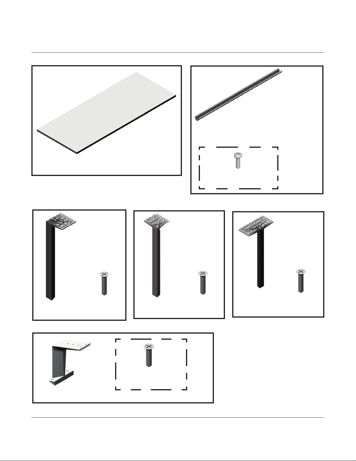
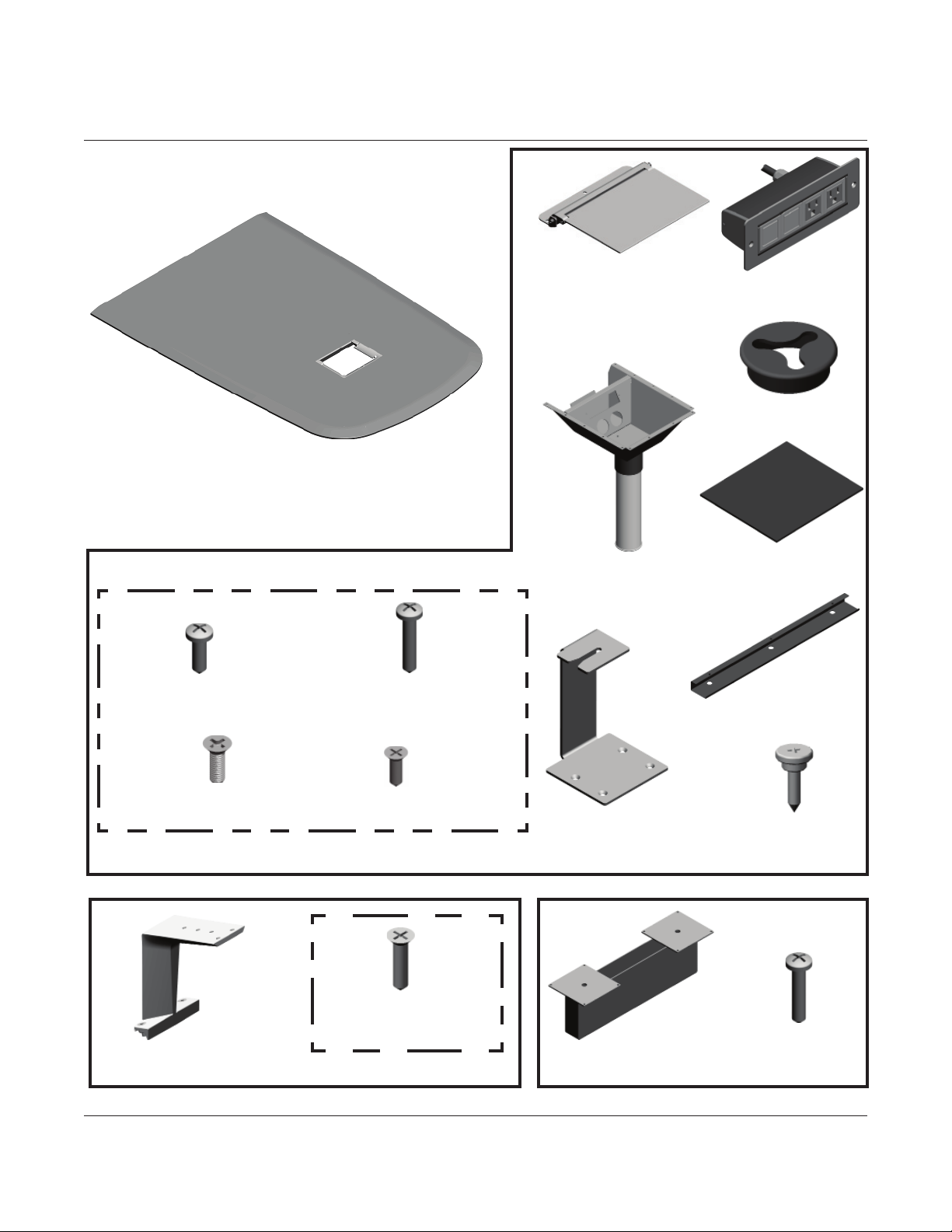
Parts Included For Surface:
LH Leg RH Leg
Shared
Leg
Work Surface
Dock to Surface Tether
(Work Surface)
(Stiffener)
(FT2B2.FR) (FD2B2.FS)
(FT2B2.FL)
(FD290)
Stiffener
DFG
A
H
EEE
B
10-12 x 7/8 Flat Hd
Tapping Screw (5)
10-12 x 3/4 Pan Head
Tappiing Screw
10-12 x 1 Flat
Hd Tapping
Screw (11)
10-12 x 1 Flat
Hd Tapping
Screw (11)
10-12 x 1 Flat
Hd Tapping
Screw (10
J
C
Hardware Pack
Z
© 2015 Herman Miller, Inc. Zeeland, Michigan. Printed in the U.S.A.
Part no. 1BDWNJ rev B.
TM Y, L, Canvas Office Landscape are among the trademarks of Herman Miller, Inc.
Illustrations and specifications are based on the latest product information available at the time of publication.
The right is reserved to make changes in design and specifications at any time, without notice, and also to discontinue products. 2
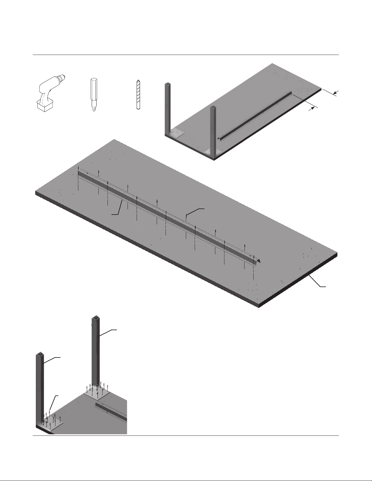
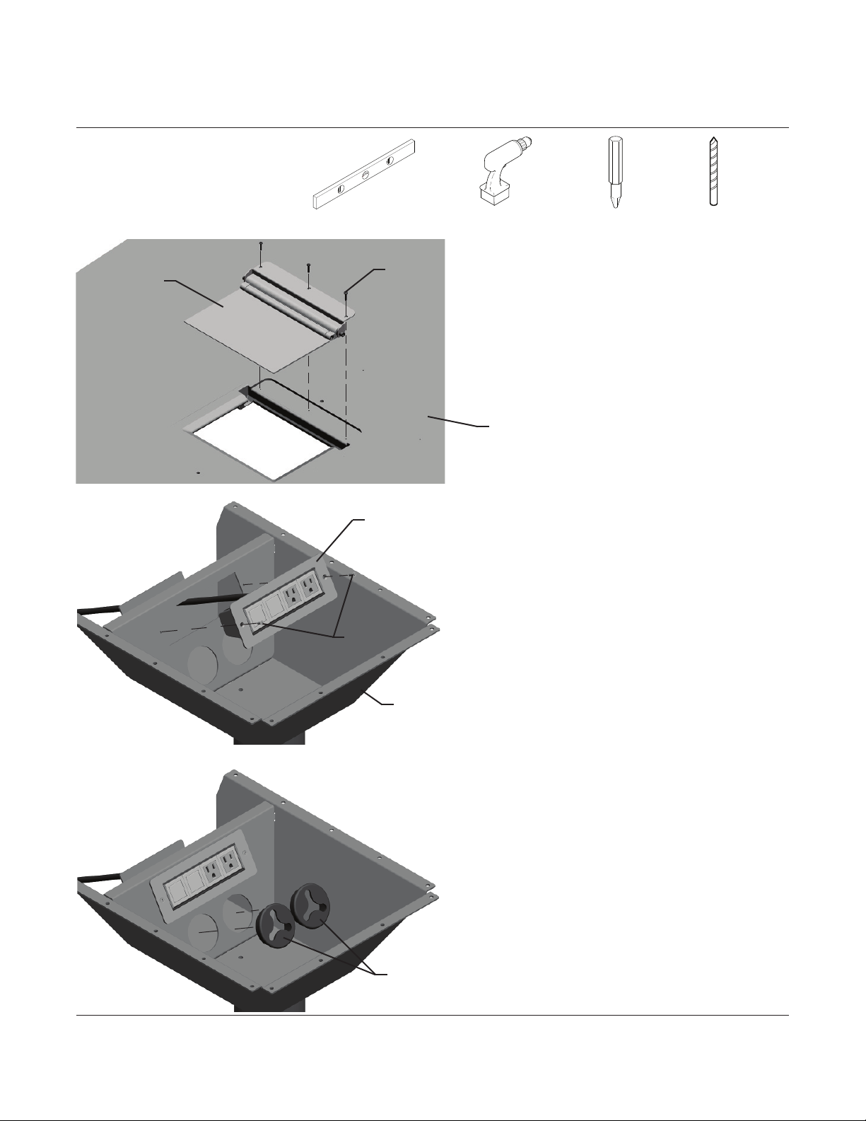
Tools Required:
Power Driver #2 Phillips Bit 1/8” Drill Bit
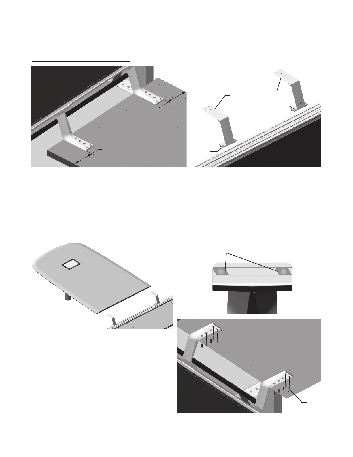
1. Place perpendicular mounted work surface (A)
face down on clean padded surface.
2. Assemble Stiffener (B) to work surface with pan
head tapping screws (C). Install Stiffener
recomended in planning guide so that it is
minimum of 10” between end of Stiffener and
edge of surface that will attach to dock to allow
for under surface power module.
3. Attach LH Leg (D) and RH Leg (F) to work
surface with flat head tapping screws (E).
A
C
F
D
E
B
10” Min.
Z
© 2015 Herman Miller, Inc. Zeeland, Michigan. Printed in the U.S.A.
Part no. 1BDWNJ rev B.
TM Y, L, Canvas Office Landscape are among the trademarks of Herman Miller, Inc.
Illustrations and specifications are based on the latest product information available at the time of publication.
The right is reserved to make changes in design and specifications at any time, without notice, and also to discontinue products. 3
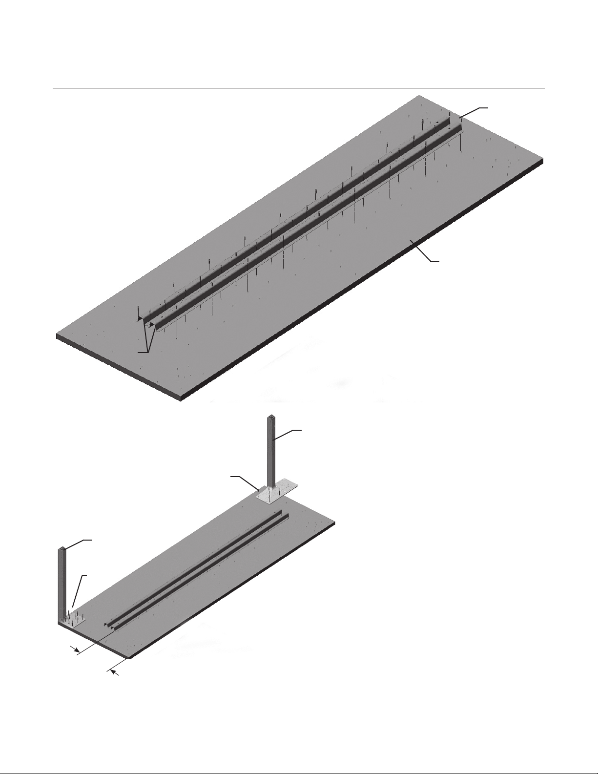
4. Place parrallel mounted work
surface (A) face down on
clean padded surface.
5. Assemble 2 Stiffeners (B)
to work surface with pan
head tapping screws (C).
Use front most sets of pre-
drilled holes. There must
be a minimum of 10” of space
between back edge of
surface and edge of Stiffener
to allow for under surface
power module. This may
require new pilot holes in
some surfaces.
6. Attach LH Leg (D) and/or RH
Leg (F) to work surface
with flat head tapping
screws (E). Use Shared Leg
(G) when ganging work
surfaces end to end.
Note: There will be a 1/8” gap
between surfaces if
predrilled holes in surface
are used to locate Shared
Leg.
G
D
E
E
A
C
B
10” Min.
Z
© 2015 Herman Miller, Inc. Zeeland, Michigan. Printed in the U.S.A.
Part no. 1BDWNJ rev B.
TM Y, L, Canvas Office Landscape are among the trademarks of Herman Miller, Inc.
Illustrations and specifications are based on the latest product information available at the time of publication.
The right is reserved to make changes in design and specifications at any time, without notice, and also to discontinue products. 4
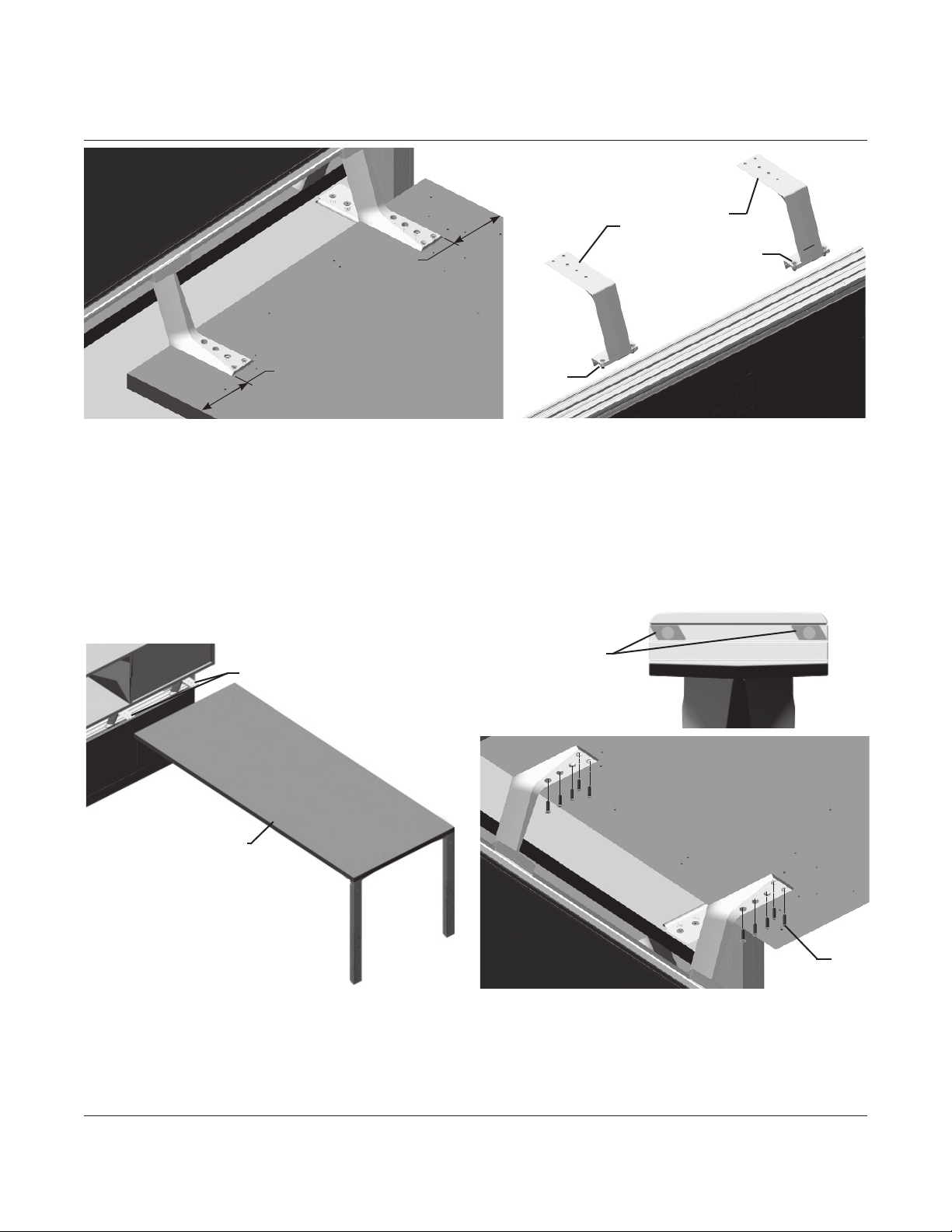
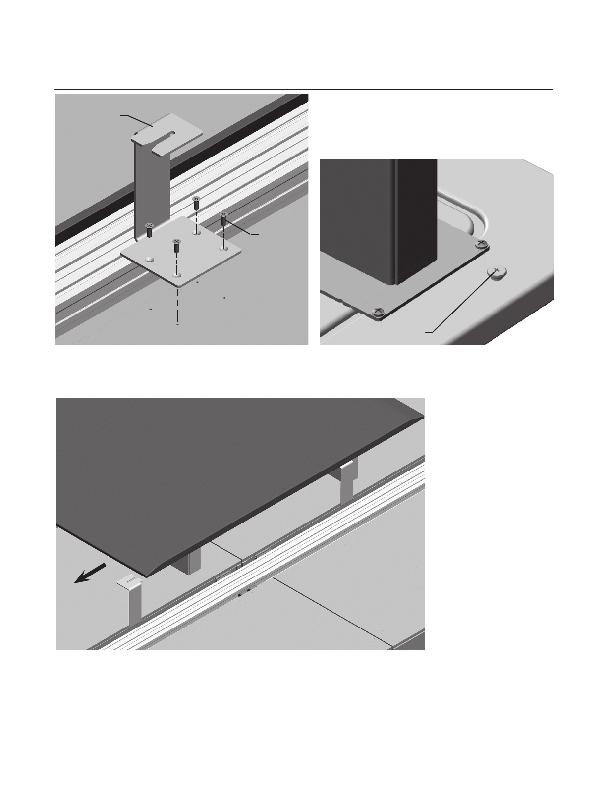
11. Place work surface assembly onto tether in proper location, with back edge of
surface aligned with back edge of tether.
13. Using tethers as template, drill 5 pilot holes per tether. Be careful not to
drill through top.
14. Attach work surface to supports with 5 flat head screws (J) per support.
7. Determine where work surface is to be installed. Dock to Surface Tethers are
to be mounted 3 1/2” in from edge of work surface.
8. Back out dock mounting screws in Dock to Surface Tethers (H) until T-nuts
hang loose.
9. Insert T-nuts into groove in top rail of dock.
10. Slide top support into appropriate position. Tighten screws. Pull up on tether
to ensure T-nuts are engaged in slot in rail. If not, check to see if T-Nuts are
intalled properly on tethers.
H
J
H
Work Surface
T-nuts
Tethers
T-Nut
Dock Mounting
Screw
3.5”
3.5”

Z
© 2015 Herman Miller, Inc. Zeeland, Michigan. Printed in the U.S.A.
Part no. 1BDWNJ rev B.
TM Y, L, Canvas Office Landscape are among the trademarks of Herman Miller, Inc.
Illustrations and specifications are based on the latest product information available at the time of publication.
The right is reserved to make changes in design and specifications at any time, without notice, and also to discontinue products. 5
Shared Leg
Shared Leg
16. Install next work surface as described above.
17. Attach Shared Leg to work surface with 5 flat head tapping screws (E).
15. For parallel mounted work surface, mount surface assembly with Shared Leg
first. Follow steps 7 through 14. Also add a third Dock to Surface Tether (H),
for surfaces greater than 48”, as close to center of top as possible.
H
H
H
H
H
H
Z
© 2015 Herman Miller, Inc. Zeeland, Michigan. Printed in the U.S.A.
Part no. 1BDWNJ rev B.
TM Y, L, Canvas Office Landscape are among the trademarks of Herman Miller, Inc.
Illustrations and specifications are based on the latest product information available at the time of publication.
The right is reserved to make changes in design and specifications at any time, without notice, and also to discontinue products. 6
Parts Included For
Peninsula:
Work Surface
A
G
B
F
C
HM
JL
L
KN
Wire Trough
Flipper Door
Rubber Pad
Bottom Pan
Tether Bracket(2) Thumb Screw(2)
Grommet (2)
Hardware Pack
#10-12 x 5/8 lg Pan
Hd Tapping Screw (6)
#10-12 x 3/4 lg Pan Hd
Tapping Screw (14)
#10-12 x 3/4 lg
Pan Hd Tapping
Screw (8)
#8-32 x 1/2 lg Flat Hd
Screw (2)
#10-12 x 5/8 lg Flat
Hd Tapping Screw (8)
Power Tap
E
D
Dock to Surface Tether Surface Support
(FD290)
(FD600)
(FDS60)
(FDT60)
(FDE60)
(FT298_M)
PS
10-12 x 7/8 Flat Hd
Tapping Screw (5)
R
Hardware Pack
Z
© 2015 Herman Miller, Inc. Zeeland, Michigan. Printed in the U.S.A.
Part no. 1BDWNJ rev B.
TM Y, L, Canvas Office Landscape are among the trademarks of Herman Miller, Inc.
Illustrations and specifications are based on the latest product information available at the time of publication.
The right is reserved to make changes in design and specifications at any time, without notice, and also to discontinue products. 7
1. Place Peninsula Work Surface (A)
upside down on a clean padded
surface.
2. Position Flipper Door (B) into
opening in work surface.
3. Install 3 pan head screws (J).
4. Insert Power Tap (D) into cutout in
Bottom Pan (C).
5. Install 2 flat head screws (K).
6. Press 2 grommets (E) into
openings in Bottom Pan.
BJ
A
K
D
C
E
Tools Required:
Power Driver
Level #2 Phillips Bit 1/8” Drill Bit

Z
© 2015 Herman Miller, Inc. Zeeland, Michigan. Printed in the U.S.A.
Part no. 1BDWNJ rev B.
TM Y, L, Canvas Office Landscape are among the trademarks of Herman Miller, Inc.
Illustrations and specifications are based on the latest product information available at the time of publication.
The right is reserved to make changes in design and specifications at any time, without notice, and also to discontinue products. 8
L
C
J
G
S
S
L
L
10. Position Wire Trough (G) over
pilot holes in work surface.
11. Install 3 pan head screws (J).
7. Place Bottom Pan (C) over
opening in work surface.
8. Align pilot holes in work surface
with holes in Bottom Pan.
9. Install 14 pan head screws (L).
12. Position two Surface Supports (S)
over Pilot holes in work surface.
13. Install using pan head screws (L)
provided with Surface Support.
Pilot Holes
Pilot Holes
Pilot Holes
Pilot Holes
Storage Mounted Peninsula:

Z
© 2015 Herman Miller, Inc. Zeeland, Michigan. Printed in the U.S.A.
Part no. 1BDWNJ rev B.
TM Y, L, Canvas Office Landscape are among the trademarks of Herman Miller, Inc.
Illustrations and specifications are based on the latest product information available at the time of publication.
The right is reserved to make changes in design and specifications at any time, without notice, and also to discontinue products. 9
14. Remove tops from credenzas where peninsula is to be installed.
15. Assemble Tether Brackets (H) to Peninsula Surface with Shoulder Screws (M).
H
H
M
M
16. Place peninsula upright and position onto credenza.
17. Align back edge of Tether Brackets with back of credenzas.
18. Mark hole location on credenzas.
19. Remove peninsula from credenzas.
20. Remove Tether Bracket from peninsula.
21. Drill 1/8” diamiter pilot holes in credenzas.
Mark
Holes
Align
a
rk
o
l
es
Ali
gn
Z
© 2015 Herman Miller, Inc. Zeeland, Michigan. Printed in the U.S.A.
Part no. 1BDWNJ rev B.
TM Y, L, Canvas Office Landscape are among the trademarks of Herman Miller, Inc.
Illustrations and specifications are based on the latest product information available at the time of publication.
The right is reserved to make changes in design and specifications at any time, without notice, and also to discontinue products. 10
22. Attach Tether Bracket (H) to credenza with flat head tapping screws (N).
23. Keep Shoulder Screws loose in peninsula surface.
H
N
Shoulder Screw
24. Return tops to credenzas.
25. Place peninsula surface onto credenzas. Slide surface over to engage
tether brackets with shoulder screws. (Sheet of paper under stanchion pad
makes top easier to slide.) Tighten shoulder screws.
Z
© 2015 Herman Miller, Inc. Zeeland, Michigan. Printed in the U.S.A.
Part no. 1BDWNJ rev B.
TM Y, L, Canvas Office Landscape are among the trademarks of Herman Miller, Inc.
Illustrations and specifications are based on the latest product information available at the time of publication.
The right is reserved to make changes in design and specifications at any time, without notice, and also to discontinue products. 11
Dock Mounted Peninsula:
12. Determine where work surface is to be installed. Dock to Surface Tethers are
to be mounted 3 1/2” in from edge of work surface.
13. Back out dock mounting screws in Dock to Surface Tethers (P) until T-nuts
hang loose.
14. Insert T-nuts into groove in top rail of dock.
15. Slide top support into appropriate position. Tighten screws. Pull up on tether
to ensure T-nuts are engaged in slot in rail. If not, check to see if T-Nuts are
intalled properly on tethers.
PP
T-Nut
Dock Mounting
Screw
3.5”
3.5”
R
16. Place work surface assembly onto
tether in proper location, with back
edge of surface aligned with back
edge of tether.
17. Using tethers as template, drill 5
pilot holes per tether. Be careful not
to drill through top.
18. Attach work surface to supports
with 5 flat head screws (R) per
support.
T-nuts

Z
© 2015 Herman Miller, Inc. Zeeland, Michigan. Printed in the U.S.A.
Part no. 1BDWNJ rev B.
TM Y, L, Canvas Office Landscape are among the trademarks of Herman Miller, Inc.
Illustrations and specifications are based on the latest product information available at the time of publication.
The right is reserved to make changes in design and specifications at any time, without notice, and also to discontinue products. 12
26. Level work surface by rotating leg
in or out to adjust.
Rotate Leg
27. Place Rubber Pad (F) onto the floor
of the Bottom Pan. (Note: Work
Surface not shown for clarity.)
F
Both Mounted Peninsulas:

Z
© 2015 Herman Miller, Inc. Zeeland, Michigan. Printed in the U.S.A.
Part no. 1BDWNJ rev B.
TM Y, L, Canvas Office Landscape are among the trademarks of Herman Miller, Inc.
Illustrations and specifications are based on the latest product information available at the time of publication.
The right is reserved to make changes in design and specifications at any time, without notice, and also to discontinue products. 13
Disassembly for Recycling:
Materials Identification and Segregation:
Where possible, plastic components are marked with ASTM recycling codes.
Use these codes to identify material type for recycling. Non-marked components
should be treated as mixed plastic. Ferrous metals can be identified using a
small magnet for recycling. Non-ferrous metals should be separated and recycled
separately.
To disassemble product, reverse the above installation steps.
Other manuals for Canvas Office Landscape
12
Table of contents
Other Herman Miller Office Equipment manuals

Herman Miller
Herman Miller Canvas Office Landscape In-Line Beam... Installation instructions

Herman Miller
Herman Miller Canvas Office Landscape Support Panel Installation instructions

Herman Miller
Herman Miller 1BKTM2-A User manual

Herman Miller
Herman Miller Canvas Office Landscape Installation instructions

Herman Miller
Herman Miller FT194.A Installation instructions

Herman Miller
Herman Miller Action Office User manual


