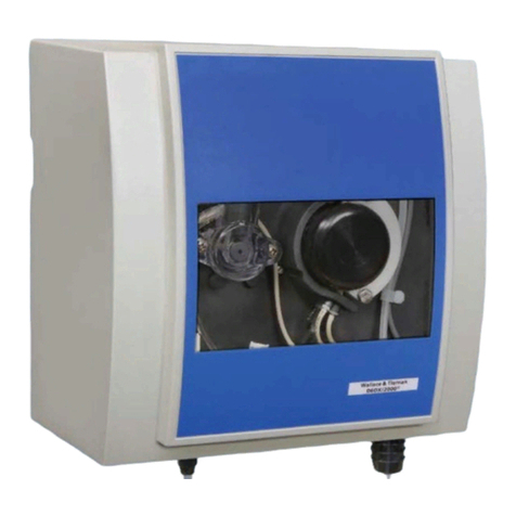
Evoqua DEPOLOX User manual

1
INSTRUCTION MANUAL
DEPOLOX®400 M
WALLACE & TIERNAN®
DISINFECTION ANALYZER
Version 1.14 and later

DEPOLOX® 400 M
2
EN
In some countries, DEPOLOX, OSEC, Barrier, Chem-Ad and Wallace & Tiernan are trademarks of Evoqua, its subsidiaries or
affiliated companies. No part of this document may be reproduced in any form (printed, photocopy, microfilm, or any other
procedure) or saved, processed, copied, or distributed using electronic data systems - without the express prior written con-
sent of Evoqua Water Technologies GmbH.
All information in this document is considered reliable and corresponds to the generally applicable technical standards. Evo-
qua assumes no responsibility for the completeness of this information. Users are responsible for making sure that the pro-
duct is suitable for specific applications. Evoqua assumes no liability for specific or indirect damage or consequential
damage arising from the sale, resale or misuse of its products.
NOTICE
Translation of the original instruction.

DEPOLOX® 400 M Contents
3
EN
Contents
1. Introduction ............................................................................... 5
1.1 Target groups ..........................................................................................................5
1.2 Structure of the documentation .............................................................................5
1.3 Conventions.............................................................................................................5
2. Safety......................................................................................... 6
2.1 Intended use............................................................................................................6
2.2 General safety instructions .....................................................................................6
2.3 Specific operating phases........................................................................................7
2.4 Warranty conditions................................................................................................7
2.5 Exclusion of liability.................................................................................................7
3. Description................................................................................. 8
3.1 General ....................................................................................................................8
3.2 Versions...................................................................................................................8
3.3 Configuration options..............................................................................................9
3.4 Overview of sensors (DES sensors)........................................................................10
3.5 Optional accessories..............................................................................................10
3.6 400 M electronics module.....................................................................................11
3.7 DEPOLOX® 5 C flow cell .........................................................................................15
3.8 VariaSens C flow cell..............................................................................................16
3.9 Y-style flow-through assembly ..............................................................................18
3.10 Sensors ..................................................................................................................18
3.11 Technical data .......................................................................................................21
4. Interfaces ................................................................................. 28
4.1 USB interface.........................................................................................................28
4.2 RS485 interface .....................................................................................................28
4.3 Ethernet interface .................................................................................................28
4.4 Modbus TCP interface ...........................................................................................31
5. Installation ............................................................................... 38
5.1 Scope of delivery ...................................................................................................38
5.2 Transport and storage...........................................................................................38
5.3 Required ambient conditions................................................................................38
5.4 Mechanical Installation .........................................................................................38
5.5 Installation of the module .....................................................................................39
5.6 Removing and fittting the housing cover ..............................................................41
5.7 Installing the optional strainer ..............................................................................42
5.8 Connecting the sample water inlet .......................................................................42
5.9 Connecting the sample water outlet.....................................................................43
5.10 Prepare the DEPOLOX® 5 C flow cell .....................................................................43
5.11 Prepare the VariaSens C flow cell..........................................................................45
5.12 Installing sensors ...................................................................................................45
5.13 Connecting sensors ...............................................................................................47

Contents DEPOLOX® 400 M
4
EN
5.14 Electrical installation............................................................................................. 48
5.15 Initial commissioning ............................................................................................ 50
5.16 Replace 4-way mA output card............................................................................. 51
5.17 Shut-down............................................................................................................. 51
5.18 Start-up ................................................................................................................. 51
6. Operation ................................................................................ 52
6.1 Display and control elements ............................................................................... 52
6.2 “Measurement” menu.......................................................................................... 53
6.3 “System“ menu ..................................................................................................... 56
6.4 Web visualization.................................................................................................. 64
6.5 Firmware update .................................................................................................. 65
6.6 Calibration............................................................................................................. 66
6.7 Messages, alarms and errors ................................................................................ 70
6.8 Faults and remedies.............................................................................................. 73
7. Maintenance............................................................................ 74
7.1 Automatic maintenance and calibration check intervals...................................... 74
7.2 Maintenance intervals .......................................................................................... 74
7.3 Maintenance parts set for flow cell ...................................................................... 75
7.4 Checking for leaks ................................................................................................. 75
7.5 Servicing the DEPOLOX® 5 C flow cell................................................................... 75
7.6 Cleaning or replacing the fine filter of Varia Sens C.............................................. 77
7.7 Cleaning the flow rate monitor and non-return ball valve ................................... 78
7.8 Cleaning or replacing the optional strainer .......................................................... 79
7.9 Replacing the fuses on the CPU board.................................................................. 79
7.10 Replacing the battery............................................................................................ 79
7.11 Cleaning ................................................................................................................ 79
8. Spare parts, Accessories and Retrofit kits ................................. 80
8.1 400 M electronics module .................................................................................... 80
8.2 DEPOLOX® 5 C flow cell......................................................................................... 82
8.3 DEPOLOX® 5 C flow cell......................................................................................... 84
8.4 VariaSens C flow cell ............................................................................................. 86
8.5 VariaSens C flow cell ............................................................................................. 88
8.6 Cell body cover, DEPOLOX® 5 C flow cell.............................................................. 90
8.7 Cell body, VariaSens C flow cell ............................................................................ 91
8.8 Y-style flow-through assembly non-pressurized version - W3T167442 ............... 92
8.9 Sensors, connector-cable combination and extension cable ............................... 93
8.10 Membrane sensors and extension cable .............................................................. 94
8.11 Accessories............................................................................................................ 95
9. Wiring diagram ....................................................................... 96
10. EC Declaration of Conformity and Certificate.......................... 100

DEPOLOX® 400 M 1. Introduction
5
EN
1. Introduction
1.1 Target groups
This operating manual provides the informa-
tion required for installation, operating and
maintenance personnel for the installation,
operation and maintenance of the DEPOLOX®
400 M disinfection analyzer.
All personnel working with and on the DEPO-
LOX® 400 M must have read and understood
the operating manual, particularly the safety
instructions.
1.2 Structure of the documentation
This operating manual contains important
information for the safe, trouble-free and eco-
nomical operation of the
DEPOLOX® 400 M
. A
thorough review of these instructions will help
to prevent danger, reduce repair costs and
downtimes and increases the reliability and
service life of the
DEPOLOX® 400 M
.
The Chapters Installation and Maintenance
are intended only for trained and authorized
service personnel. These chapters contain
important information on the assembly, confi-
guration, start-up, maintenance and repair,
which must be performed by this target group.
1.3 Conventions
This operating manual contains a number of
notes with different priorities that are labeled
with pictograms.
DANGER
Immediate danger to life and limb! If the
situation is not corrected, death or serious
injury will result.
WARNING
Danger to life and limb! If the situation is not
corrected, death or serious injury can result.
ATTENTION
If this note is not observed, moderate or
minor injury or damage to equipment can
result.
WARNING
Electrocution hazard.
ATTENTION
Environmental hazard!
Do not throw away or burn the batteries!
Batteries must be disposed of at a collection
point.
NOTICE
These notes indicate a material risk or pro-
vide useful information to make working
with the DEPOLOX® 400 M easier.

2. Safety DEPOLOX® 400 M
6
EN
2. Safety
2.1 Intended use
The DEPOLOX® 400 M disinfection analyzer
with installed sensors is designed exclusively
for measurement of the parameters free chlo-
rine, total chlorine, chlorine dioxide, ozone,
potassium permanganate, pH value, ORP vol-
tage (Redox), fluoride and temperature in
drinking water.
The operational safety is only guaranteed if
the DEPOLOX® 400 M is used in accordance
with its intended application. The DEPOLOX®
400 M may only be used for the purpose defi-
ned in the order and under the installation,
operating and ambient conditions specified in
this operating manual.
All inspection and maintenance work must be
carried out at the specified intervals.
Compliance with the intended use also inclu-
des reading this operating manual and obser-
ving all the instructions therein.
The owner/operator of the installation bears
sole responsibility for consequences of any
use that does not conform with the installa-
tion’s intended use.
2.2 General safety instructions
The manufacturer places great emphasis on
safety when working on or with the DEPO-
LOX® 400 M disinfection analyzer. This is taken
into account, starting with the design of the
installation, by the integration of safety fea-
tures.
Safety regulations
The safety instructions in this documentation
must be observed at all times. Additional
industry-wide or in-house safety regulations
also continue to apply.
Safety instructions on the DEPOLOX® 400 M
All safety instructions attached to the DEPO-
LOX® 400 M must be observed. These instruc-
tions must always be clearly legible and
complete.
State-of-the-art technology
The DEPOLOX® 400 M has been constructed in
accordance with the technological state-of-
the-art and the accepted rules of safety engi-
neering. However, if the DEPOLOX® 400 M is
used by persons who have not been adequa-
tely instructed, danger to the life and limb of
such persons or third parties and damage to
the unit itself or to other property cannot be
ruled out. Work not described in this operating
manual must be performed only by authorized
personnel.
Personnel
The operator of the overall system must
ensure that only authorized and qualified spe-
cialist personnel are permitted to work with
and on the DEPOLOX® 400 M. “Authorized
specialist personnel” are trained, skilled per-
sonnel employed by the owner/operator, the
manufacturer or, if applicable, the service
partner. Work on electrical components must
be carried out by qualified electricians.
Spare parts / components
Trouble-free operation of the DEPOLOX®
400 M is only guaranteed if original spare
parts and components are used in precisely
the combination described in this operating
manual. Failure to observe this instruction
may lead to malfunctions or damage to the
DEPOLOX® 400 M.
Extensions and conversions
Any modifications, extensions or conversions
to the DEPOLOX® 400 M that could impair its
safety require the written approval of the
manufacturer.
Electrical power
Only qualified electricians or trained person-
nel supervised by a qualified electrician are
permitted to perform any work on electrical
components and must do so in accordance
with valid electro-technical regulations.
During normal operation, the controller must
remain closed. Connect power cables in accor-
dance with the wiring diagram.
DANGER
Risk of injury or death!
The DEPOLOX® 400 M must not be operated
with flammable liquids
DANGER
Risk of injury or death!
External voltages may still be connected
even if the operating voltage is switched off.
In the event of a fault in the electrical power
supply, switch the DEPOLOX® 400 M off
immediately.

DEPOLOX® 400 M 2. Safety
7
EN
IT security
The manufacturer offers IT security mecha-
nisms for its products to support secure sys-
tem operation. We recommend checking on a
regular basis to see what information is availa-
ble regarding IT security developments for
your products. Information on this can be
found on the Internet. Moreover, for the safe
operation of an installation, it is also necessary
to integrate the automation components into
a holistic IT security concept which comprises
the entire system and is in accordance with
the state of the art in IT technology. Integra-
ted products from other manufacturers
should also be taken into account.
During commissioning of the
DEPOLOX®
400 M
, the factory-configured passwords and
user names should be replaced with individual
ones and the user administration enabled.
Disposal
Ensure safe and environment-friendly disposal
of agents and replacement parts. Dispose of
electronic waste in accordance with local and
national regulations.
2.3 Specific operating phases
• Never employ any working methods
which could affect safety!
• Never operated with flammable liquids.
• The DEPOLOX® 400 M may only be opera-
ted with the housing closed!
• Inspect the DEPOLOX® 400 M at least
once daily for externally visible damage
and faults! Inform the responsible per-
son/authority immediately of any detec-
ted changes (including any changes in the
operating performance)!
• In the event of malfunctions, always
switch the electronics module off imme-
diately! Have malfunctions remedied
immediately!
• During installation and maintenance
work, secure the DEPOLOX® 400 M
against being switched back on!
• If stipulated, disconnect all parts of the
electronics module from the power sup-
ply before performing any inspection,
maintenance or repair work. Then first
test the disconnected components to
ensure they do not carry any voltage.
• Never use corrosive cleaning agents (e.g.
spirit, scouring agents)!
2.4 Warranty conditions
The following must be observed for compli-
ance with warranty conditions. If any of the
conditions are not met, the warranty is void.
• Installation and commissioning by the
manufacturer or trained and authorized
specialist personnel, e.g. from contracted
companies.
• Intended use
• Observation of the operational parame-
ters and settings.
• The unit may only be operated by trained
personnel.
• An operating log book must be kept (only
in the public sector).
• Only approved calibration chemicals may
be used.
• The unit must not be exposed to frost.
• The prescribed maintenance work must
be carried out.
• Use of original spare parts.
2.5 Exclusion of liability
We are not liable for any damages incurred
during installation or use of these hardware
and software components. This applies speci-
fically to trouble-free interaction with the
software and hardware components you
choose.
We accept no liability for any loss sustained by
the buyer (in particular, lost profits, lost infor-
mation and service interruptions) arising
through the use of the DEPOLOX® 400 M nor
for other damage. You are solely responsible
for the installation!
The content of the operating manual has been
checked to make sure that it matches the
hardware and software described. Neverthe-
less, deviations cannot be ruled out, and we
therefore assume no liability for full confor-
mity. The details in this operating manual are
checked regularly and any necessary correcti-
ons included in subsequent issues.

3. Description DEPOLOX® 400 M
8
EN
3. Description
3.1 General
The DEPOLOX® 400 M disinfection analyzer
has a modular design structure and comprises:
• 400 M electronics module (module name
E02)
• Flow cell (module name D02) or Y-style
flow-through assembly
•DEPOLOX®5C
non-pressurized or pressurized version
• VariaSens C
non-pressurized or pressurized version
• Y-style flow-through assembly
non-pressurized version
•Sensors
Depending on the sensors installed, the DEPO-
LOX® 400 M can measure the parameters free
chlorine, total chlorine, chlorine dioxide,
ozone, potassium permanganate, pH value,
ORP voltage (Redox), fluoride and tempera-
ture.
Depending on the sensors installed, the elec-
tronics module has two up to three measuring
inputs. One measuring input is used to mea-
sure disinfectants such as free chlorine, total
chlorine, chlorine dioxide, ozone or potassium
permanganate. The second measuring input
to measure the pH value or fluoride. The third
measuring input to measure the ORP voltage
(Redox).
Various flow cells are available. The DEPOLOX®
5 C flow cell has an open 3-electrode cell and
the VariaSens C flow cell holds the membrane
sensors. The flow cells can be fitted with seve-
ral sensors. Depending on the application and
the sensor used, a non-pressurized or pressu-
rized flow cell must be used; see configuration
overview on chapter 3.3. The transparent cell
body allows visual monitoring of the sensors
and the sample water. An LED glow stick sig-
nals the alarm, warning, and error messages
by a change in color.
Free chlorine measurement with the DEPO-
LOX® 5 C depends on the pH value. By using a
pH measurement, the pH dependency of the
measurement can be compensated for within
a range of pH 6.00 to pH 8.75 (Cl2++).
The Y-style flow-through assembly is available
in a non-pressurized version and can be used
with a pH, ORP (Redox) or fluoride sensor.
3.2 Versions
Part No. 400 M electronics module
(module name E02)
W3T441932
2-channel disinfection
analyzer and 4-way mA out-
put module (factory installed)
Part No. Flow cell (module name D02)
W3T389205 DEPOLOX® 5 C
non-pressurized version
W3T389210 DEPOLOX® 5 C
pressurized version
W3T440600 VariaSens C
non-pressurized version
W3T440611 VariaSens C
pressurized version
Part No.
Y-style flow-through assembly
W3T167442 non-pressurized version
Part No. Sensor measuring modules
W3T441935 TC3 (total chlorine)
W3T441936 FC2 (free chlorine)
W3T443072 CD7 (chlorine dioxide)
W3T443073 OZ7 (ozone)
W3T441938 pH
W3T391868 ORP (Redox)
W3T441937 Fluorid

DEPOLOX® 400 M 3. Description
9
EN
3.3 Configuration options
Description
DEPOLOX® 5 C
non-
pressurized
version
DEPOLOX® 5 C
pressurized
version
VariaSens C
non-
pressurized
version
VariaSens C
pressurized
version
Y-style flow-
through
assembly
non-
pressurized
version
A 3-Electrode cell (free
chlorine)
B Blind plug
C Fluoride sensor (only on
non-pressurized version)
DpHsensor
ELEDglowstick
F ORP sensor (Redox)
A Fluoride sensor (only on
non-pressurized version)
B Membrane sensors TC3,
FC2, CD7, OZ7
CLEDglowstick
D ORP sensor (Redox)
EpHsensor
F Blind plug
ApH-,
ORP (Re-
dox) or
fluoride
sensor
3-electrode cell
(free chlorine) XX - - -
Membrane sensor TC3
--XX-
Membrane sensor FC2
--XX-
Membrane sensor CD7
--XX-
Membrane sensor OZ7
--XX-
pH sensor X X X X X
ORP sensor (Redox) X X X X X
Fluoride Sensor X - X - X
Sample water tem-
perature (multi-
sensor)
XXXX-
Flow rate monitor
(multi-sensor) XXXX-
Sample water eart-
hing (multi-sensor) XXXX-
Sample water fine
filter (fine filter),
only when using
membrane sensors
X-XX-
LED glow stick X X X X -
Ball valve on the
sample water inlet XXXX-
Ball valve on the
sample water outlet -X-X-
ABC
FED
AB
FED
AB
ED C
B
EC
D F
A

3. Description DEPOLOX® 400 M
10
EN
3.4 Overview of sensors (DES sensors)
3.5 Optional accessories
For part numbers, see chapter 8.
• Mounting plate with accessories (chapter
8.11)
• Impedance converter (chapter 5.4)
• Extension cable for sensors (chapter 5.4)
• Strainer (chapter 5.7)
• Booster pump (chapter 5.8)
• Pressure reducing valve (chapter 5.8)
• PVC- or PE version, hose and tubing
connection (chapter 5.8)
Description 3-electrode cell
(DEPOLOX® 5 C)
TC3
(total
chlorine)
FC2
(free
chlorine
CD7
(chlorine
dioxide)
OZ7
(ozone)
Measuring
principle
Potentiostatic
3-electrode cell
with platinum
electrodes
Membrane-covered,
amperometrically
operating potentiostatic
3-electrode system with
integrated electronics
Membrane-covered
2-electrode system
Measured value
Free Cl2, ClO2,
O3, KMnO4,
Cl2++ for pH-
compensated
free Cl2mesure-
ment
Total chlorine
Free chlorine
Chlorine
dioxide
(ClO2)
Ozone (O3)
Area of
application
Drinking water,
high level of
hardness and
fast reaction
time
Drinking water, suitable for
low conductivity and fluc-
tuating pH value
In water with dirt
particles < 0.8 mm

DEPOLOX® 400 M 3. Description
11
EN
3.6 400 M electronics module
3.6.1 Design
Fig. 1 400 M electronics module
A Touchsreen/display
B Plastic housing with removable housing
cover
C Motherboard with power supply, terminal
strips, electronic components and relays
D Cable glands
3.6.2 Functions
The electronics module is used for the measu-
rement of auxiliary hygiene parameters in
drinking water applications:
• Free chlorine, chlorine dioxide, ozone or
potassium permanganate with 3-elec-
trode cell (DEPOLOX® 5 C)
• Total chlorine measurement with memb-
rane sensor TC3
• Free chlorine with membrane sensor FC2
• Chlorine dioxide with membrane sensor
CD7
• Ozone with membrane sensor OZ7
•pHvalue
• ORP voltage (Redox)
• Fluoride
•Temperature
Typical applications:
• Measurement of chlorine, ORP (Redox)
and pH
• Monitoring and notification of an alarm if
limit values exceeded
• Data visualization
• Data transfer to higher-level systems
For connection to a visualization system, there
is an optional 4-way mA output module, an
RS485 interface and an Ethernet interface with
Modbus TCP and HTTP protocol.
3.6.3 Controller outputs
The electronics module has a dosing contact
for disinfection measurement.
3.6.4 Messages
Alarms, warnings, errrors and messages are
displayed using a colored message symbol (tri-
angle with an exclamation mark).
Red symbol: alarm or error active
Yellow symbol: non-acknowledgeable alarms
active
Orange symbol: maintenance interval or cali-
bration interval has elapsed
Press the symbol and the message window
opens. All active text messages are displayed.
They are acknowledged via ACK button.
3.6.5 Alarms
The electronics module supports up to eight
freely configurable alarms. The alarms can be
assigned to a relay contact and noted on the
color display. At the same time, a message is
displayed in the message window and the
message system is displayed. The number of
available relays depends on the configuration.
A maximum of six alarm relays are possible,
depending on if the controller disinfection
output is used. The alarm relays can be used,
for example, for safety deactivation of dosing
when specific values are exceeded or not rea-
ched.
Each alarm can be assigned the following func-
tions. Multiple assignment is possible:
A
B
C
D
Limit value
Min 1 and Min 2 =>
all measuring
values can be selec-
ted individually
Limit value
Max 1 und Max 2
Digital inputs => 1 to 5 can be selec-
ted individually
Error

3. Description DEPOLOX® 400 M
12
EN
Acknowledgment “none“
• The alarm symbol and the message sym-
bol light up in the event of an alarm and
go out automatically when the condition
is eliminated.
• Unlatched alarms are displayed in yellow
as messages.
• The relay is active when the alarm symbol
is displayed and the alarm is active.
Fig. 2 Acknowledgment “none“
Acknowledgment “ACK with reset“
• In the event of an alarm, the alarm sym-
bol and the message symbol flash and the
relay is active until acknowledged.
• The alarm symbol and the message go out
even if the conditions still apply when the
alarm is acknowledged.
• Latched alarms are displayed in red as
messages.
• The relay becomes inactive after acknow-
ledgment if the condition is still pending.
Fig. 3 Acknowledgment “ACK with reset“
Acknowledgment “simple ACK“
• The relay becomes active as soon as the
alarm is active.
• In the event of an alarm, the alarm sym-
bol and the message symbol flash until
the alarm is acknowledged.
• If the condition is no longer present when
the alarm is acknowledged, the alarm
symbol goes out and the message disap-
pears.
• If the condition is still present when the
alarm is acknowledged, the alarm symbol
and the message are reset from flashing
to a permanent state. The alarm symbol
and the message light up until the condi-
tion is eliminated (auto-reset).
• Latched alarms are displayed in red as
messages.
• The relay is only deactivated when the
condition has been eliminated and ack-
nowledged.
Fig. 4 Acknowledgment “simple ACK“
3.6.6 Safety functions
The electronics module is equipped with vari-
ous integrated safety functions to ensure sys-
tem safety and minimize the risk of accidents.
The following safety functions are integrated:
• safety deactivation if the sample water
flow is too low and/or if the dosing tank
signals that it is empty (depending on the
configuration of the digital inputs)
• alarms freely configurable
• external STOP for dosing (depending on
the configuration of the digital inputs)
• password protection with three levels
• Safety MAN. mode
stops dosing with sample water stop or
external stop
Alarm condition
Symbol without
Relay without
Symbol with
Relais with
delay time
delay time
delay time
delay time
Alarm condition
Symbol without
Relay without
Symbol with
Relay with
delay time
delay time
delay time
delay time
flashing flashing
Alarm condition
Symbol without
Relay without
Symbol with
Relay with
delay time
delay time
delay time
delay time
flashing flashing

DEPOLOX® 400 M 3. Description
13
EN
Sample water monitoring
The sample water monitoring must be che-
cked regularly. Without automatic detection
of a shortage of sample water or an excessi-
vely low flow rate, there is a risk of uncontrol-
led dosing of chemicals. The sample water
monitoring deactivates dosing if there is a
shortage of sample water and prevents the
uncontrolled dosing of chemicals.
3.6.7 Digital inputs
There are five integrated digital inputs on the
CPU board of the electronics module. They are
provided for connection of voltage-free con-
tacts (< 100 Ohm) and are supplied internally
with 24 V.
The functions of the digital inputs can be con-
figured for the specific customer application n
the "Input/Output” menu. Digital input 1 is
used for sample water monitoring and cannot
be changed.
Digital input DI 1
With the help of the voltage-free contact of
the flow rate monitor on the flow fitting, the
controllers can be influenced:
• before expiry of the sample water moni-
toring delay time (0 to max. 10 min.):
Dosing continues at the same rate
The symbol on the display flashes.
Display:
• after expiry of the sample water monito-
ring delay time:
Dosing is switched off.
Display:
Digital input DI 2 to DI 5
Various functions can be assigned to the digi-
tal inputs. With the help of a voltage-free ena-
bling contact, e.g. circulation off, the
controllers can be stopped immediately:
• Use as an alarm (freely configurable).
• The chlorine dosing pump and the dosing
pump for pH correction are switched off.
The positioner moves to 0 %.
Display: (example)
• Empty signal contact of the chemical
tank(s).
The chlorine dosing pump and the dosing
pump for pH correction are switched off.
The positioner moves to 0 %.
Display: (example)
• Standby function
When the Standby function is activated,
all controllers are switched off and dosing
is deactivated. The alarms are disabled.
Measured value displays are hidden.. This
function is used to switch off the circula-
tion to prevent measurements and incor-
rect controller outputs.
DANGER
Risk of injury or death
If there is a shortage of sample water or the
flow rate is too low, there is a risk of uncon-
trolled dosing of chemicals. To ensure safe
operation and prevent injury, the sample
water monitoring must never be disabled.
Never disable the sample water monitoring -
even temporarily, e.g. by bridging the signal
input.
WARNING
Do not apply voltages at the digital input ter-
minals!
NOTICE
Controller switch-off is only effective in
“Safety MAN. mode“.
NOTICE
Controller switch-off is only effective in
“Safety MAN. mode“.
NOTICE
When the contact closes, restart of the cont-
roller may be delayed due to the dosing
delay time. In as-delivered status, the digital
inputs are disabled. To activate the function,
connect an external contact and configure
the digital input in the menu. The digital
inputs can also be assigned as alarms.
DI 2
DI 3

3. Description DEPOLOX® 400 M
14
EN
3.6.8 Relay outputs
The electronics module has a maximum of six
relays, each with a changeover contact. These
switches are assigned various switching tasks
depending on the respective application. The
corresponding diagrams are defined in chap-
ter 9. “Wiring diagrams”.
The connection and switching of non-permis-
sible loads / loads destroys the relay contacts.
The device works uncontrollably as a result!
In order to switch inductive loads or larger
capacitive loads, which exceed the technical
characteristics of the relay contact, an additi-
onal switching element must be installed. For
example a contactor or load relay with suita-
ble specification. Relay contact details see
chapter 3.11 "Technical Data" - Relay outputs.
To protect radio interference suppression, the
relay contacts are protected internally by sup-
pressor diodes. Relay outputs are protected by
fuses. They act as overcurrent limiters protec-
ting the terminal and relay connections. The
fuses are replaceable. Spare fuses see chapter
8.
Fig. 5 Detail of PCB - relay outputs
ARelay
B Terminal strips
CFuses
3.6.9 Interfaces
The interfaces are described in detail in chap-
ter 4. The following interfaces are available:
•USBinterface
• RS485 interface
•Ethernetinterface
•ModbusTCPinterface
NOTICE
If the internal power supply L1 and N/L2 is
used for dosing pumps or other devices, the
total current consumption must not exceed
6 A.
AB C

DEPOLOX® 400 M 3. Description
15
EN
3.7 DEPOLOX® 5 C flow cell
The DEPOLOX® 5 C flow cell has a 3-electrode
cell and is available in a non-pressurized or
pressurized version. The versions also differ in
the number and layout of the sensors that can
be installed and in the design of the sample
water outlet.
3.7.1 Design
Fig. 6 Cross-section, DEPOLOX® 5 C flow cell,
pressurized version
A Cover to hold the sensors and the LED glow
stick (cell body cover)
B Cell body
C 3-electrode cell with electrolyte storage
tank
D Cap of the 3-electrode cell
E Sample water outlet with ball valve (on
non-pressurized version without ball valve)
F Flow cell drain valve
G Sample water inlet with ball valve
H Filter unit
I Check valve housing
J Flow control valve
KMulti-sensor
3.7.2 Function
The following section describes the functional
principle of the DEPOLOX® 5 C flow cell from
the sample water inlet to the sample water
outlet (see chapter 3.7.1).
The sample water is connected on the input
side via the G1/2” connection on the ball
valve. The input pressure must be around 4 to
45 psig (0.25 to 3.0 bar). To guarantee a cons-
tant flow, the minimum input pressure must
not be less than 4 psig (0.25 bar). If the pres-
sure is lower, an optional booster pump must
be used. If the inlet pressure exceeds 45 psig
(3.0 bar), an optional pressure reducing valve
must be used.
The sample water flows over the optional
strainer, which prevents dirt particles pene-
trating into the flow cell.
The check valve ensures the sample water can
only flow in the correct direction.
The multi-sensor monitors the correct flow
following the float principle with reed switch
and records the temperature with a Pt1000
sensor. Large-area sample water earth ground
is via the stainless steel sensor housing.
The flow control valve ensures a flow of the
sample water that is not dependent on the
operating pressure. The correct sample water
flow of 0.15 gal/min (33 l/h) is preset, checked
and documented at the factory.
The cell body contains the 3-electrode cell
with external potentiostatic control loop and a
refillable electrolyte storage tank. Working
and counter electrode are designed as semi-
annular electrodes and made from a special
platinum alloy. A silver-silver chloride elec-
trode connected to the sample water via two
diaphragms serves as the reference electrode.
The reference electrode is dipped into an elec-
trolyte solution which can refilled as needed.
GF E
A
B
C
D
K
J
I
H
NOTICE
The DEPOLOX® 5 C flow cell can be used for
the measurement of free chlorine, ozone,
potassium permanganate and chlorine
dioxide. It must be ensured that only one of
these disinfection agents is present in the
water.

3. Description DEPOLOX® 400 M
16
EN
The sample water flows tangentially into the
3-electrode cell ensures continual hydro-
mechanical cleaning of the sensor electrodes
with a special cleaning sand and thus prevents
the natural contamination of the electrode
surfaces. Clean electrode surfaces and a cons-
tant flow of sample water are critical for high-
quality oxidant measurement and greater
responsiveness.
The adjustable cell voltage Upot is output via
the potentiostatic control loop. The cell cur-
rent (µA signal) is proportional to the concen-
tration of disinfection agent in the sample
water and is evaluated with the electronics
module.
The HOCl characteristic curve describes the
influence of the pH value on the DEPOLOX®
5 C and the influence of temperature.
Fig. 7 HOCl characteristic curve
The cell body contains the sensors and the LED
glow stick. The sensors are installed in the
location holes in the cell body cover with stan-
dardized threaded connections or in special
sensor holders. The LED glow stick is installed
in the cell body cover to visually monitor the
sensors and to signal messages and errors in
color.
On the pressurized version, the sample water
supply is connected on the output side via the
G 1/2” connection on the ball valve. At this
point, a maximum back pressure of 22 psig
(1.5 bar) is permitted.
On the non-pressurized version, the sample
water runs off via a drain connection for hoses
with an internal diameter of 6 mm directly via
the cell body outlet at the top.
The flow cell drain valve can be used to collect
a sample for calibration. It is used to draw
sample water from the cell body through the
low-pressure side of the flow control valve or
to drain the cell body for servicing purposes.
3.8 VariaSens C flow cell
The VariaSens C flow cell is available in a
non-
pressurized
or pressurized version. The versi-
ons also differ in the number and layout of the
sensors that can be installed and in the design
of the sample water outlet.
3.8.1 Design
Fig. 8 Cross-section, VariaSens C flow cell,
non-pressurized version
A Cover to hold the sensors and the LED glow
stick (cell body cover)
B Plastic housing with removable housing
cover
C Flow control valve
D Cell body
E Sample water outlet (on the pressurized
version, with ball valve)
F Flow cell drain valve
G Sample water inlet with ball valve
H Fine filter
I Check valve housing
JMulti-sensor
K Calibration holding clip
C
A
B
D
E
F
K
J
I
H
G

DEPOLOX® 400 M 3. Description
17
EN
3.8.2 Function
The following section describes the functional
principle of the VariaSens C flow cell from the
sample water inlet to the sample water outlet
(see chapter 3.8.1).
The sample water supply is connected on the
input side via the G1/2” connection on the ball
valve. The input pressure must be around 4 to
45 psig (0.25 to 3.0 bar). To guarantee a cons-
tant flow, the minimum input pressure must
not be less than 4 psig (0.25 bar). If the pres-
sure is lower, an optional booster pump must
be used. If the inlet pressure exceeds 45 psig
(3.0 bar), an optional pressure reducing valve
must be used.
The sample water flows over the optional
strainer, which prevents dirt particles pene-
trating into the flow cell.
In the direction of flow, the sample water
flows through the filter unit or through the
installed fine filter (only with membrane sen-
sors) to the check valve housing. The check
valve ensures sample water is only in the cor-
rect direction. The fine filter is only used in
conjunction with membrane sensors.
The multi-sensor monitors the correct flow
following the float principle with reed switch
and records the temperature with a Pt1000
sensor. Large-area sample water earth ground
is via the stainless steel sensor housing.
The flow control valve ensures a flow of the
sample water that is not dependent on the
operating pressure. The correct sample water
flow of 0.15 gal/min (33 l/h) is preset, checked
and documented at the factory. If the inlet
pressure increase, the control valve moves to
keep the flow constant, if the inlet pressure
drops, the control moves to keep the flow
constant.
The cell body contains the sensors and the LED
glow stick. The sensors are installed in the
location holes in the cell body cover with stan-
dardized threaded connections or in special
sensor holders. The LED glow stick is installed
in the cell body cover to visually monitor the
sensors and to signal messages and errors in
color.
On the pressurized version, the sample water
supply is connected on the output side via the
G 1/2” connection on the ball valve. At this
point, a maximum back pressure of 22 psig
(1.5 bar) is permitted.
On the non-pressurized version, the sample
water runs off via a drain connection for hoses
with an internal diameter of 6 mm directly via
the cell body outlet at the top.
The flow cell drain valve can be used to collec-
ted a sample for calibration. It is used to draw
sample water from the cell body through the
low-pressure side of the flow control valve or
to drain the cell body for servicing purposes.
NOTICE
The VariaSens C flow cell can be used in
combination with membrane sensors for
the measurement of free chlorine, total
chlorine, ozone and chlorine dioxide. It must
be ensured that only one of these disinfec-
tion agents is present in the water and that
the cross-sensitivity of the sensors is all-
owed for.

3. Description DEPOLOX® 400 M
18
EN
3.9 Y-style flow-through assembly
The Y-style flow-through assembly is available
in a non-pressurized version and can be fitted
with a pH, ORP (Redox) or fluoride sensor.
3.9.1 Design
Fig. 9 Y-style flow-through assembly
A Sensor holder
B Outlet (open)
C Output
D Sample water valve
E Sample water inlet
3.9.2 Function
The following section describes the functional
principle of the Y-style flow-through assembly
from the sample water inlet to the sample
water outlet (see chapter 3.9.1). The installa-
tion of a ball valve on the input side is recom-
mended.
The sample water supply is connected on the
input side via the 1/2” NPT connection. A ball
valve for setting the sample water flow must
be provided on site.
The sample water flows over the optional
strainer, which has a mesh size of 0.2“
(0.5 mm) and prevents dirt particles penetra-
ting into the Y-style flow-through assembly.
The strainer must be provided on site.
The sample water supply is connected on the
output side via the 1/2” NPT connection. The
sample water outlet is not pressurized.
The pH, ORP (Redox) or fluoride sensor is
mounted in the sensor holder.
3.10 Sensors
The sensors are screwed into the cell body
cover of the flow cell and connected to the
electronics module.
The pH, ORP (Redox) and fluoride sensor can
also be installed via the Y-style flow-through
assembly and connected to the flow cell.
3.10.1 DEPOLOX® 5 C - 3-electrode cell
See chapter 3.7.2 “3-electrode cell”.
3.10.2 pH sensor
The pH sensor is designed as a pH single-rod
measuring cell.
The pH-sensitive element is the membrane
made of special silicate glass, a rounded tip at
the lower end of the pH sensor. The reference
electrode is a silver/silver chloride electrode
(Ag/AgCl) and, together with the pH elec-
trode, forms the measuring cell. The reference
electrode is the stable electrical reference
point for voltage measurement.
The electrolyte is a saturated potassium chlo-
ride solution. As the chloride concentration of
the electrolyte remains almost constant, the
potential of the reference electrode is also
constant. Salt rings as an additional salt depot
further increase the service life of the pH sen-
sor.
A ceramic membrane permeable for the elec-
trolyte provides the electrical connection to
the measuring solution. This ceramic memb-
rane is particularly suitable for the treatment
of water in swimming pools and baths and
drinking water, as the electrolyte can only
flow slowly through the pores of the ceramic
pin, thus ensuring very long service life for the
entire pH sensor.
AB
EDC
NOTICE
The pH sensor can be installed in the non-
pressurized and pressurized version of the
DEPOLOX® 5 C and VariaSens C flow cells.
The pH sensor can also be installed in the Y-
style flow-through assembly for individual
measurement.

DEPOLOX® 400 M 3. Description
19
EN
The pH sensor is installed in an electrolyte
reservoir (transport container) with diluted
electrolyte which protects the sensitive mem-
brane, keeps the membrane moist and thus
ensures that the measuring cell is ready for
immediate use. If the pH sensor is not used,
e.g. over the winter, the pH sensor must be
plugged in the transport container with dilu-
ted electrolyte (KCl tank with stand and 5 ml
KCl solution).
3.10.3 ORP sensor (mV)
The ORP sensor consists of a ORP combination
electrode. The ORP sensor consists of a glass
shaft with a platinum or gold tip fused into its
lower end.
Together with a silver/silver chloride elec-
trode (Ag/AgCl) as a reference electrode, it
forms a measuring chain. The task of the refe-
rence electrode is to provide a constant
potential during potentiometric measure-
ments. This potential is measured against the
potential of the metal electrode.
The electrolyte is a saturated potassium chlo-
ride solution. As the chloride concentration of
the electrolyte remains almost constant, the
potential of the reference electrode is also
constant. Salt rings as an additional salt depot
further increase the service life of the ORP
sensor.
A ceramic membrane permeable for the elec-
trolyte provides the electrical connection to
the measuring solution. This ceramic memb-
rane is particularly suitable for the treatment
of drinking water and water in swimming
pools and baths, as the electrolyte can only
flow slowly through the pores of the ceramic
pin, thus ensuring very long service life for the
entire measuring chain.
The ORP sensor is installed in an electrolyte
container with diluted electrolyte which pro-
tects the sensitive membrane, keeps the
membrane moist and thus ensures that the
measuring cell is ready for immediate use.
When the ORP sensor is not in use, for exam-
ple during the winter, we recommend storing
it in the transport container in diluted electro-
lyte.
The following reference values apply for quick
and complete disinfection of the water in
swimming pools and baths:
3.10.4 Fluoride sensor
Fluoride measurement using a fluoride-ion-
selective electrode is used for continuous
identification of fluoride ions in the solution.
To obtain a correct reading, the pH value of
the measured medium must be within a range
from pH 5 to pH 8.
The reference system is filled with electrolyte.
NOTICE
The ORP sensor (Redox) can be installed in
the non-pressurized and pressurized version
of the DEPOLOX® 5 C and VariaSens C flow
cells. The ORP sensor (Redox) can also be
installed in the Y-style flow-through assem-
bly for individual measurement.
Fresh water
pH 6,5 to 7,3 UG > 750 mV
pH 7,3 to 7,6 UG > 770 mV
NOTICE
The fluoride sensor can be installed in the
non-pressurized version of the DEPOLOX®
5 C and VariaSens C flow cells.
The fluoride sensor can also be installed in
the Y-style flow-through assembly for indivi-
dual measurement.
ATTENTION
Rapid, repeated changes in temperature
result in a constant change in the potential.
This can cause functional failure of the elec-
trode.

3. Description DEPOLOX® 400 M
20
EN
3.10.5 Membrane sensors TC3 (total
chlorine) and FC2 (free chlorine)
The membrane sensor is a membrane-cove-
red potentiostatic 3-electrode measuring cell
with a specially positioned counter electrode.
The measuring electrode is membrane-cove-
red and located, together with the reference
electrode, in an electrolyte chamber that is
separated from the sample water and con-
tains a special electrolyte.
In this measurement method, chlorine diffu-
ses from the sample water through the mem-
brane and, in combination with the
electrolyte, triggers an electrical signal at the
measuring electrode. This electrical signal is
proportional to the chlorine concentration
and is amplified by the membrane sensor elec-
tronics. As a result of integrated temperature
compensation, the measuring signal is inde-
pendent of the sample water temperature.
3.10.6 Membrane sensor CD7 (chlorine
dioxide)
Membrane sensor CD7 allows selective mea-
surement of the chlorine dioxide content in all
types of water, including ultrapure water (LF >
1µS/cm), without cross-sensitivity to chlorine,
bromine and hydrogen peroxide, but cross-
sensitive to ozone and peracetic acid. Memb-
rane sensor CD7 does not exhibit pH-depen-
dency and is therefore suitable for water with
changing pH values.
3.10.7 Membrane sensor OZ7 (ozone)
Membrane sensor OZ7 allows selective mea-
surement of the chlorine dioxide content in all
types of water, including ultrapure water (LF >
1µS/cm), without cross-sensitivity to chlorine,
bromine and hydrogen peroxide, but cross-
sensitive to chlorine dioxide and peracetic
acid. Membrane sensor OZ7 does not exhibit
pH-dependency and is therefore suitable for
water with changing pH values.
NOTICE
The membrane sensors TC3 and FC2 can be
installed in the non-pressurized and pressu-
rized version of the VariaSens C flow cell.
NOTICE
Membrane sensor CD7 can be installed in the
non-pressurized and pressurized version of
the VariaSens C flow cell.
NOTICE
Membrane sensor OZ7 can be installed in the
non-pressurized and pressurized version of
the VariaSens C flow cell.
Other manuals for DEPOLOX
1
Table of contents
Other Evoqua Measuring Instrument manuals
Evoqua
Evoqua IONPURE IP-MXM30 Manual

Evoqua
Evoqua V10K User manual

Evoqua
Evoqua WALLACE & TIERNAN MICRO/2000 User manual

Evoqua
Evoqua WALLACE & TIERNAN P7 ADVANCED User manual

Evoqua
Evoqua WALLACE & TIERNAN SFC BA W3T166501 User manual
Evoqua
Evoqua WALLACE & TIERNAN GMS PLUS User guide

Evoqua
Evoqua WALLACE & TIERNAN DEPOLOX 400 M User manual

Evoqua
Evoqua Wallace & Tiernan SFC-SC User manual
Evoqua
Evoqua DEPOLOX POOL COMPACT WALLACE & TIERNAN User manual

Evoqua
Evoqua Wallace & Tiernan Depolox 3 plus User manual


