Evoqua DEPOLOX Pool E User manual

WALLACE & TIERNAN®FLOW CELL MODULE
DEPOLOX POOL E
INSTRUCTION MANUAL

2WT.050.810.020.DE.IM.0115
Flow cell module DEPOLOX Pool E
Please note
Original instruction manual!
Simone

Flow cell module DEPOLOX Pool E Contents
3
Contents
1. Introduction 5
1.1 Documentation 5
1.2 Disclaimer 6
1.3 Conventions 7
2. Safety 9
2.1 Intended use 9
2.2 General safety instructions 10
2.3 Specific operating phases 11
2.4 Notes on Special Dangers 12
2.5 Warranty conditions 12
3. Description 13
3.1 General 13
3.2 Versions 15
3.3 Design 17
3.4 Function 18
3.5 Technical data 22
4. Installation 29
4.1 Scope of delivery 29
4.2 Transport and storage 30
4.3 Mechanical installation 31
4.4 First commissioning 46
4.5 Shut-down 47
4.6 Renewed start up 48

4WT.050.810.020.DE.IM.0115
Contents Flow cell module DEPOLOX Pool E
5. Maintenance 49
5.1 Maintenance intervals 49
5.2 Maintenance parts kit 50
5.3 Checking for leakages 51
5.4 Checking the electrode cleaning sand 51
5.5 Replacing the electrode cleaning sand 51
5.6 Cleaning the fine filer 52
5.7 Cleaning the flow rate monitor and non-return
ball valve 53
5.8 Cleaning 53
6. Retrofit kits and spare parts 55
6.1 Retrofit kits 55
6.2 Retrofitting sensor measuring modules 56
6.1 Spare parts 58
7. Drawings 63
7.1 Flow cell module DEPOLOX Pool E
non-pressurized version 63
7.2 Flow cell module DEPOLOX Pool E
pressurized version 65
7.3 Electronic box DFMe 67
8. Certificates 69
9. Index 71

Flow cell module DEPOLOX Pool E Introduction
1.
5
1. Introduction
1.1 Documentation
1.1.1 Target groups
This instruction manual provides the information for installation,
operating and maintenance personnel. It is required for operation
and maintenance of the flow cell module DEPOLOX Pool E.
This instruction manual is intended for operators of the flow cell
module DEPOLOX Pool E. It contains important information for
safe, trouble-free and efficient operation of the flow cell module
DEPOLOX Pool E. Observing these instructions will help prevent
risks, reduce repair costs and downtimes, and increases the
reliability and service life of the flow cell module DEPOLOX Pool E.
Sections installation and maintenance are intended only for
trained service personnel. These sections contain important
information on assembling, configuring, and commissioning the
flowcellmoduleDEPOLOXPoolEandonmaintenanceandrepair
work.
Allthose workingwith the flowcell moduleDEPOLOX Pool Emust
have read and understood the instruction manual and, in
particular, the safety instructions.
Please consult the table of contents and the index to quickly find
the information you require.

6WT.050.810.020.DE.IM.0115
Introduction Flow cell module DEPOLOX Pool E
1.
1.2 Disclaimer
We are not liable for any damages incurred during installation or
use of these hardware and software components. This applies
specifically to trouble-free interaction with the software and
hardware components you choose.
We are not liable forbuyer damages (in particular, lost profits, lost
information and service interruptions), which arise when using the
flow cell module DEPOLOX Pool E, nor for other damages. You
are solely responsible for the installation!
The contents of the instruction manual has been checked to make
sure that it matches the detailed hardware and software.
Deviations can nevertheless not be ruled out and we therefore
assume no liability for full conformity. The details in this instruction
manual are checked regularly and any necessary corrections are
included in subsequent issues.

Flow cell module DEPOLOX Pool E Introduction
1.
7
1.3 Conventions
Please note
This instruction manual contains a number of notes with different
priorities that are marked with symbols.
Pictogram Note Meaning
Danger! Immediate danger to life and limb! If
the situation is not corrected, death
or serious injury will result.
Warning! Danger to life and limb! If the
situation is not corrected, death or
serious injury can result.
Attention! If this note is not observed,
moderate or minor injury or damage
to equipment can result.
Warning! Electrocution hazard.
Please
note These notes indicate a material risk
or provide useful information to
make working with the device
easier.
Attention! Environmental hazard!
Do not throw away or burn the
batteries!
Batteries must be disposed of at a
collection point.

8WT.050.810.020.DE.IM.0115
Introduction Flow cell module DEPOLOX Pool E
1.

Flow cell module DEPOLOX Pool E Safety
2.
9
2. Safety
2.1 Intended use
The flow cell module DEPOLOX Pool E is intended exclusively for
the measurement and control of the treatment of water in
swimming pools and baths.
The operational safety of the flow cell module DEPOLOX Pool E is
only guaranteed if it is used in accordance with its intended
application. It may only be used for the purpose defined in the
order and under the installation, operating and ambient conditions
specified in this instruction manual.
All inspection and maintenance work must be carried out in
accordance at the specified intervals.
Compliance with the intended use also includes reading this
instruction manual and observing all the instructions it contains.
The owner/operator of the installation has sole responsibility for
consequences of any use that does not conform with the
installation’s intended use.

10 WT.050.810.020.DE.IM.0115
Safety Flow cell module DEPOLOX Pool E
2.
2.2 General safety instructions
Evoqua Water Technologies GmbH attaches great importance to
ensuring that work on its device is always perfectly safe. This was
already taken into account in the design of the installation by the
integration of safety features.
Safety regulations The safety instructions in this documentation must be observed at
all times. Additional industry-wide or in-house safety regulations
also continue to apply.
Safety instructions on the
unit All safety instructions attached to the unit itself must be observed.
These instructions must always be clearly legible and complete.
State-of-the-art technology The unit has been constructed in accordance with state-of-the-art
technology and the accepted safety regulations. However, if the
unit is used by persons who have not been adequately instructed,
risks to life and limb of such persons or third parties and damage
to the unit itself or to other property cannot be ruled out. Work not
described in this instruction manual must be performed only by
authorized personnel.
Personnel The operator of the overall system must ensure that only
authorized and qualified specialized personnel are permitted to
work with and on the unit within their defined scope of authority.
“Authorized specialists” refers to skilled personnel employed by
the owner/operator or by Evoqua Water Technologies GmbH or, if
applicable, the service partner. Only qualified electricians must
perform work on electrical components.
Spare parts / components Trouble-free operation of the unit is only guaranteed if original
spareparts and componentsareusedinpreciselythecombination
described in this instruction manual. Failure to observe this
instruction may incur the risk of malfunction or damage to the unit.
Extensions and conversions Never attempt to perform any modifications, extensions or
conversionson the unitthatcouldhaveanadverse affect onsafety
without the written approval of the manufacturer.
Electrical power During normal operation, the controller must remain closed.
Connect the power cables in accordance with the wiring diagram.

Flow cell module DEPOLOX Pool E Safety
2.
11
IT security Evoqua WaterTechnologiesGmbH offersITsecurity mechanisms
for its products to support secure system operation. We
recommend checking on a regular basis to see what information is
available regarding IT security developments for your products.
Information on this can be found on the Internet.
Forthesafeoperationofaninstallation,itisfurthermorenecessary
to integrate the automation components into a holistic IT security
concept which comprises the entire system and is in accordance
with latest state of the art technology. In the process, implemented
products deriving from other manufacturers should be taken into
account.
Upon start-up of the electronic module, it should be ensured that
the factory-configured passwords and user names are replaced
with individual ones.
Disposal Ensure safe and environment-friendly disposal of agents and
replacement parts.
2.3 Specific operating phases
Normal operation Never employ any working methods which could affect safety!
Only run the flow cell module when the housing is closed!
Inspecttheflow cellmoduleatleastonce daily for externally visible
damage and faults! Inform the responsible person/authority
immediately of any detected changes (including any changes in
the operating performance)!
In the event of malfunctions, alwaysswitch the flow cell module off
immediately! Have malfunctions remedied immediately!
Installation and
maintenance work Always perform installation or maintenance work in accordance
with this instruction manual or the technical documentation for
installed system components!
Secure the flow cell module against activation during installation
and maintenance work!
Always retighten released screw connections!
Never use corrosive cleaning agents (e.g. spirit)!
Use only a damp cloth to clean the device.
Ensure safe disposal of agents and replaced parts in accordance
with environmental regulations!

12 WT.050.810.020.DE.IM.0115
Safety Flow cell module DEPOLOX Pool E
2.
2.4 Notes on Special Dangers
Electrical power Only qualified electricians or trained personnel supervised by a
qualifiedelectrician are permittedto perform any work on electrical
components in accordance withvalid electro-technicalregulations.
If stipulated, disconnect all parts of the flow cell module from the
power supply before performing any inspection, maintenance or
repair work. Then first test the disconnected components to
ensure they do not carry any voltage.
The system may still be live even if the operating voltage is
switched off.
In the event of a fault in the electrical power supply, switch the flow
cell module off immediately!
Inspect/check the flow cell module of the system regularly.
Remedy any faults immediately.
Connect disconnected cables in accordance with the wiring
diagram.
2.5 Warranty conditions
The following must be observed for compliance with warranty
conditions:
• Installation and commissioning by Evoqua Water Technologies
GmbH personnel or trained and authorized specialized
personnel, e.g. of contracted companies
• Intended use
• Observation of the operational parameters and settings.
• The unit may only be operated by trained personnel.
• An operating log book must be kept (only in the public sector).
• Only approved calibration chemicals may be used
• The unit must not be exposed to frost.
• Maintenance work must be executed
• Use of genuine spare parts
If any of the above conditions are not met, the warranty is void.

Flow cell module DEPOLOX Pool E Description
3.
13
3. Description
3.1 General
The flow cell module DEPOLOX Pool E is part of the pool
management system DEPOLOX Pool E 700 P.
Theflowcell moduleDEPOLOX Pool E andsensors, together with
the electronic module 700 P is used to measure and control the
hygiene assistance parameters free chlorine, pH value and Redox
voltage, as well as combined chlorine, total chlorine, conductivity
and temperature.
A Flow cell module DEPOLOX Pool E with sensors
B Electronic module 700 P
AB

14 WT.050.810.020.DE.IM.0115
Description Flow cell module DEPOLOX Pool E
3.
Flow cell module
DEPOLOX Pool E The flow cell module DEPOLOX Pool E is a special flow cell
adapter for sample water from various pool applications.
The flow cell module DEPOLOX Pool E is available as a non-
pressurized or pressurized version.
The non-pressurized and pressurized version of the flow cell
module differ in the number of sensors that can be installed and in
the design of the sample water outlet.
The non-pressurized version is characterized by a free sample
water outlet.
With the pressurized version, the sample water can be returned to
the system circuit.
All sensors that are required for the measurement tasks in
swimming pools, are attached orscrewed into the cover of the cell
body of the flow cell module DEPOLOX Pool E.
The maintenance-free flow control valve is the main hydraulic part
of the flow cell module DEPOLOX Pool E. The task of the flow
control valve is to keep the sample water flow constant,
irrespective of fluctuations in operating pressures.
The multi-sensor monitors the correct flow and records the
temperature of the sample water. The metallic sensor housing
guarantees good sample water earthing. The continuous
hydromechanical cleaning of the electrode of the chlorine sensor
prevents the effective natural contamination of the electrode
surfaces and guarantees long-term chlorine measurements.
The transformation of the analog sensor signal for the digital
transfer to the electronic module 700 P is realized via the
electronic box DFMe. If optional sensors are used, this occurs via
the module SiDiSens LF (conductivity).

Flow cell module DEPOLOX Pool E Description
3.
15
3.2 Versions
The flow cell module DEPOLOX Pool E is configured in the factory
according to the customer's specific requirements, with the
electronic module 700 P according to the variant code. The scope
of delivery differs in the version of the flow cell module DEPOLOX
Pool E, the sensors, electronic components and accessories.
The variant code consists of 12 digits and is printed on both the
type plate and packaging sticker.
Example CPMNL4RLBDEOO
Selection of sensor measuring module for free chlorine
C Sensor measuring module DEPOLOX Pool E
5 Sensor measuring module DEPOLOX 5 E
Selection of sensor measuring module for pH value
P Sensor measuring module pH value
O No sensor measuring module pH value
Selection of sensor measuring module for Redox voltage
M Sensor measuring module Redox voltage
O No sensor measuring module Redox voltage
Selection of sensor measuring module for total chlorine
N Sensor measuring module total chlorine TC2
S Sensor measuring module total chlorine TC2-S
O No sensor measuring module total chlorine
Selection of sensor measuring module for conductivity
L Sensor measuring module conductivity
O No sensor measuring module conductivity
Selection of analog output
4 4-way mA analog output
O No mA analog output
Selection of relay board
R Additional relay board 4-way
O No additional relay board
Selection of flow cell module DEPOLOX POOL E
LFlow cell module DEPOLOX POOL E unpressurized
FFlow cell module DEPOLOX POOL E pressurized
Selection of LED lighting
B LED glow stick for flow cell module
Selection of language for instruction manual
DE Instruction manual in German
EN Instruction manual in English
FR Instruction manual in French
Not used
Not used
16 WT.050.810.020.DE.IM.0115
Description Flow cell module DEPOLOX Pool E
3.
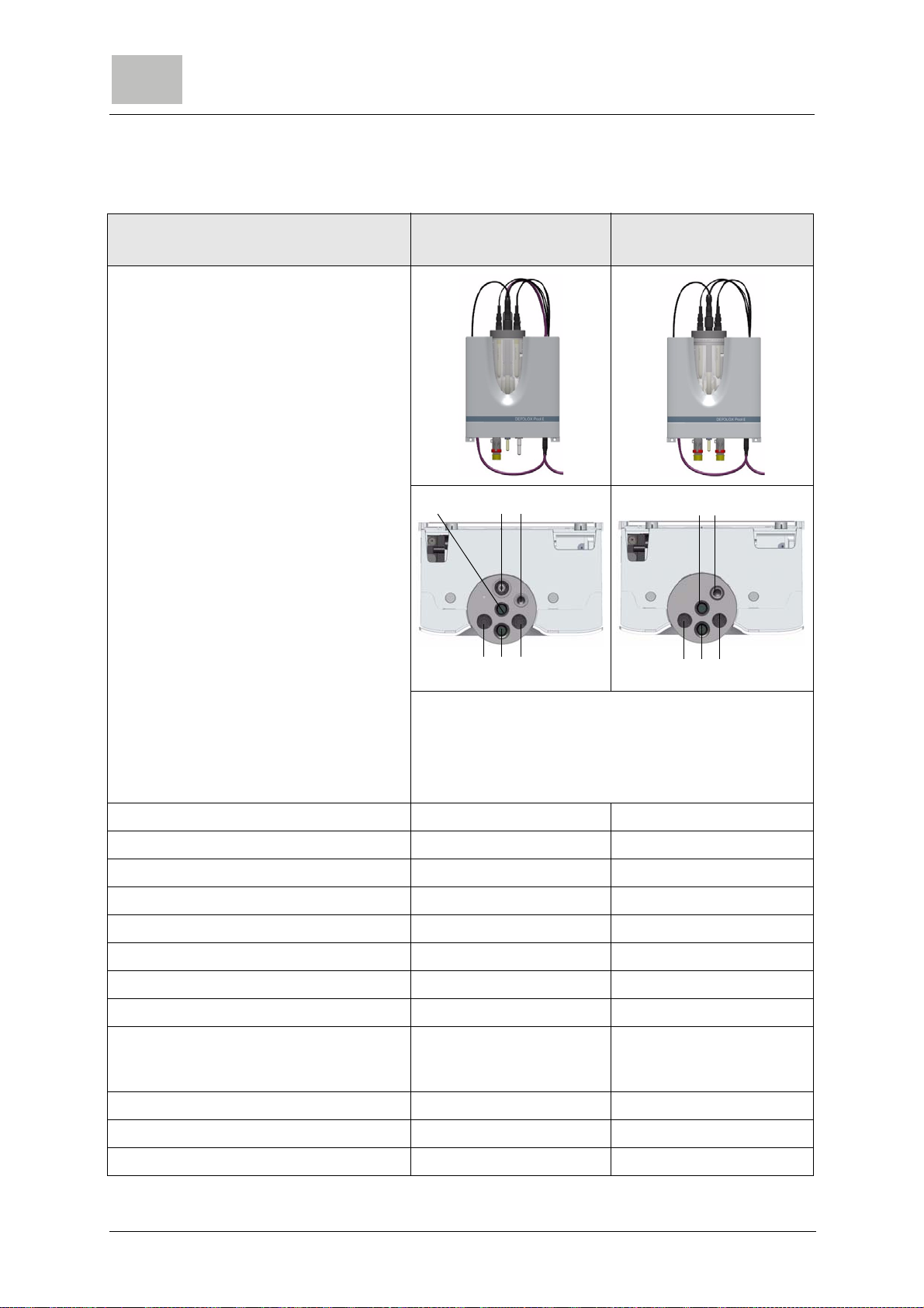
Configuration options
Description DEPOLOX POOL E
Non-pressurized version DEPOLOX POOL E
pressurized version
A Chlorine sensor (free chlorine)
B Total chlorine membrane sensor
C LED glow stick
D Redox single-rod measuring chain
E Conductivity sensor
F pH single-rod measuring chain
Chlorine sensor (free chlorine) X X
Total chlorine membrane sensor X -
pH single-rod measuring chain X X
Redox single-rod measuring chain X X
Conductivity sensor X X
Sample water temperature (multi-sensor) X X
Flow rate monitor (multi-sensor) X X
Sample water earthing (multi-sensor) X X
Sample water fine filter (X)
only when using the total
chlorine membrane sensor
-
LED glow stick X X
Ball valve (sample water inlet) X X
Ball valve (sample water outlet) - X
AB
DEF
C
AC
FED

Flow cell module DEPOLOX Pool E Description
3.
17
3.3 Design
The flow cell module DEPOLOX Pool E essentially consists of
(from the sample water inlet to the sample water outlet):
• Sample water inlet (H) with ball valve (I)
• Fine filter (J)
• Multi-sensor (L) for monitoring the flow rate, measuring the
temperature and for sample water earthing
• Flow control valve (K) for constant flow of sample water
• Cell body (B) with cover (A) to hold sensors
• Sample water outlet(F), in pressurized version also with ball
valve
• Drain/extract specimen (G)
• Electronic box DFMe (D)
• Module SiDiSens LF (M) (optional)
• Plastic housing (C) with removable housing cover
• Calibration holding clip (E) in housing cover
A
C
D
FG
I
J
E
K
M
H
E
L
B

18 WT.050.810.020.DE.IM.0115
Description Flow cell module DEPOLOX Pool E
3.
3.4 Function
3.4.1 General
The sample water is connected on the input side via the G1/2”
connection to the ball valve. The input pressure must be around
0.25 to 4.0 bar. To guarantee a constant flow, the minimum input
pressure must not be less than 0.25 bar.
In the flow direction, the connected filter unit gives the option to
install a stainless steel fine filter with a mesh size w=500 µm. The
fine filter is only used in conjunction with membrane sensors.
The return ball valve housing that is connected after the filter unit,
offers a kickback function and guides the ball for monitoring the
flow rate.
The multi-sensor combines the function of temperature
measurement of the sample water with a Pt1000, flow rate
monitoring following the float principle with reed switch and wide
area sample water earthing with stainless steel sensor housing.
A flow of the sample water that is not dependent on the operating
pressure is assured by the flow control valve. The correct sample
water flow of 33 l/h is preset at the factory, checked and logged.
The flow control valve is maintenance-free. If the admission
pressure rises, the valve ball moves towards the closing direction,
if the admission pressure drops, the ball moves towards the
opening direction.
The clear cell body holds thesensors and due to its design, is able
to provide good cleaning and service options. The sensors are
installed in the cover of the cell body with standardized threaded
connections or in special sensor holders.
The flow distributor cap screwed into the cell body from the bottom
enablesthecontinuoushydromechanicalcleaning oftheelectrode
of the chlorine sensor using special cleaning sand and thereby
effectively prevents the natural contamination of the electrode
surfaces. Clean electrode surfaces and a constant flow of sample
water are decisive criteria for a qualitative good chlorine
measurement and quick responsiveness.
The sample water runs across the top cell body outlet and directly
via a discharge nozzle for hoses with ID 6 mm or, in the case of the
pressurizedversion,via a ballvalve with G1/2” thread connection.
Withthe pressurizedversion, a maximumback pressureof1.5 bar
is permitted here.
For calibration purposes, there is also a specimen extraction
device. It is used to extract sample water from the low-pressure
side of the flow control valve in the cell body or to drain the cell
body for servicing purposes.

Flow cell module DEPOLOX Pool E Description
3.
19
Two calibration holding clips are attached in the cover of the flow
cell module. The calibration holding clips are pushed through the
side of the basic housing of the flow cell module, thereby enabling
the “hand-free” calibration of the sensors with a buffer solution
from bags or in the calibration beaker.
The electronic box DFMe is used to convert the analog sensor
signals for the digital transfer to the electronic module 700 P. The
electronic box DFMe is integrated directly in the basic housing.
The sensors and sensor cables are built in and preconfigured in
the DFMe housing and are splash-proof in accordance with IP66.
If optional sensors are used, this occurs via the module SiDiSens
LF (conductivity). This measurement module is also built into the
plastic housing of the flow cell module.
An LED glow stick is screwed into the cover of the cell body as an
optical warning indicator.
Please note
When disinfecting the inline electrolysis systems, the chlorine
sensor and Redox single-rod measuring chain must be used, gold
version (gold electrode).
For applications in brine water with conductivity levels of 2.5 to
60 mS/cm(approx.4% NaCl),thetotal chlorinemembranesensor
TC2-S must be used.
20 WT.050.810.020.DE.IM.0115
Description Flow cell module DEPOLOX Pool E
3.
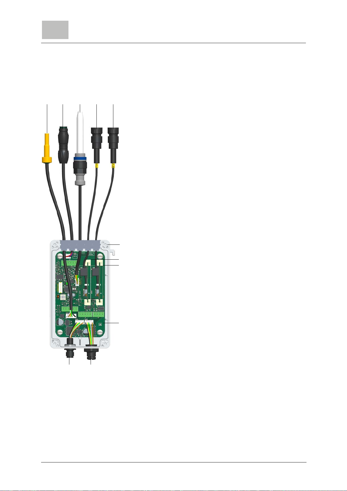
3.4.2 Electronic box DFMe
The electronic box DFMe consists of a spray-proof housing with
built-in sensor electronics.
The base plate of the electronic box DFMe includes the sensor
input for the chlorine sensor and the evaluation electronics for the
multi-sensor for the temperature measurement and flow rate
monitoring.
Two additional slots are integrated on the base plate for the pH
and Redox single-rod measuring chain.
Via the integrated CAN connection socket, the electronic box is
connected to the electronic module 700 P using the CAN
connection cable.
If additional sensors, such as total chlorine and/or conductivity are
installed, the electronic box DFMe is equipped with a second CAN
connection socket. Sensors can be retrofitted at any time (see
„retrofit kits” on page 55).
A Multi-sensor
B Sensor cable Cl2free
C LED glow stick
D pH sensor cable
E Redox sensor cable (mV)
F Housing DFMe
G pH sensor module
H Redox sensor module
I Base plate DFMe with measurement input Cl2
J CAN extension socket
K CAN connection socket for electronic module 700 P
ABCDE
H
I
F
G
JK
Table of contents
Other Evoqua Water Filtration System manuals


Popular Water Filtration System manuals by other brands


Cuckoo
Cuckoo CP-QN1401SW/WHCBMYCI user manual

Pool Technologie
Pool Technologie UNO LTE user manual

Danfoss
Danfoss AHF 005 operating instructions

Ebbco
Ebbco CLS-141-24K H.E.-SWS Operation and maintenance manual

FCI Watermakers
FCI Watermakers MAX-Q+ User manual & installation guide

3B Filters
3B Filters 8600 Series Service instructions

Dean
Dean Portable Filters MF90 Series parts manual

Eureka Forbes
Eureka Forbes Dr. Aquaguard MAGNA UV user manual

Pentair
Pentair Fleck 5800 XTR Installer manual

Aqua PRO
Aqua PRO AP-600W-A5-GST2 manual

Dräger
Dräger PAS Filter Series Instructions for use

Mayfran
Mayfran ConSep 2000-125HP Technical documentation