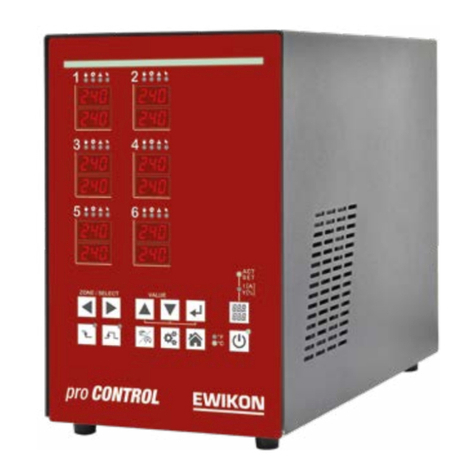
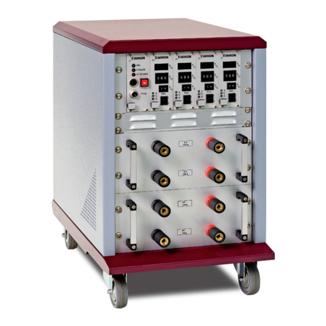
EWIKON pro CONTROL basic User manual

Hot runner controllers
Operating manual

pro CONTROL BASIC Operating manual
Page 2
Table of contents
List of Figures ..................................................................................................................... 4
1Introduction............................................................................................................ 5
1.1 Symbols used: 5
1.2 Notations 5
2Safety instructions ................................................................................................ 5
2.1 Intended use 5
2.2 Information for operators and users 5
3Structure and functionality ................................................................................... 6
3.1 General information 6
3.2 Structure 6
3.2.1 Pro CONTROL BASIC 2, 6 and 12 7
3.2.2 Operating front 7
3.2.3 LED-strip 7
3.2.4 Power card 8
3.2.5 Fuses 8
3.2.6 Notification contact / Digital input 8
3.2.7 Identification on the controller 8
3.2.8 Wiring of the plug systems 9
4Commissioning.....................................................................................................10
4.1 Electrical connection 10
4.1.1 Mains power supply 10
4.1.2 Mains connection 10
4.1.3 Connection of the mould 10
4.2 Operating and display elements 11
4.2.1 Display elements 12
4.2.1.1 Status display...........................................................................................12
4.2.1.2 Zone display.............................................................................................12
4.2.2 Operating elements 13
4.2.2.1 Main switch ..............................................................................................13
4.2.2.2 Soft keys ..................................................................................................13
5Operation ..............................................................................................................15
5.1 Zone selection 15
5.1.1 Selecting a zone 15
5.1.2 Selecting multiple zones 15
5.1.3 Selecting several consecutive zones 15
5.1.4 Selection of all zones 16
5.2 Operating mode 16
5.3 Setpoints 17
5.4 Output rate 18
5.5 Controller outputs 18
5.6 Parameter 19
5.6.1 Zone parameter 19
5.6.2 System parameter 20
5.7 Boost 21
5.8 Standby 21
6Warning and error messages...............................................................................22
6.1 Warnings 22
6.2 Alarms 23

pro CONTROL BASIC Operating manual
Page 3
7Functions and parameterization..........................................................................26
7.1 Basic settings 26
7.1.1 Access authorizations 26
7.1.2 Fahrenheit display 27
7.1.3 7.1.3 Thermocouple type 27
7.2 Control behavior 28
7.2.1 Control parameters P I D 28
7.2.2 Output level 28
7.2.3 Maximal output level 28
7.3 Heating 29
7.3.1 Softstart (Gentle heating) 29
7.3.2 Compound heating 29
7.4 Hot runner monitoring 30
7.4.1 Temperature monitoring 30
7.4.2 Average output level 32
7.4.3 Broken sensor 32
7.4.4 Heating current monitoring 32
7.4.5 Triac monitoring 33
7.5 Special functions 33
7.5.1 BOOST 33
7.5.2 STANDBY 34
7.5.3 Load detection 34
7.5.4 Default parameter 34
8Parameter overview..............................................................................................35
8.1 Zone parameter 35
8.2 System parameter 36
9Technical data.......................................................................................................37
10 Spare parts + accessories....................................................................................38
11 Appendix ...............................................................................................................39
11.1 Terminal bridges of the star-delta supply 39
11.1.1 Terminal jumpers in star network (state at delivery!) 39
11.1.2 11.1.2 Terminal bridges in delta network 39
11.2 Notification contact / Digital input 40

pro CONTROL BASIC Operating manual
Page 4
List of Figures
Figure 1 – pro CONTROL BASIC front panel 7
Figure 2 – Type label 8
Figure 3 – Wiring of plug systems 9
Figure 4 – Operating and display elements 11
Figure 5 – Zone display 12
Figure 5 – Temperature monitoring 31
Figure 6 - Star-network 39
Figure 7 - Delta-network 39

pro CONTROL BASIC Operating manual
Page 5
1 Introduction
1.1 Symbols used:
Caution/Warning Information on possible damage to property or personal injury
Information Important information
1.2 Notations
Menu structures between words are indicated by the >symbol and depicted in the same way
on the device.
Interaction with the operator is denoted by the finger symbol.
2 Safety instructions
Please read this document completely and carefully before commissioning or
operating the device.
2.1 Intended use
The hot runner controller is used to control the temperature of heating circuits and is designed
for use under precisely defined conditions, such as supply voltage and temperature. The op-
erator must therefore ensure that the controller is only used under operating conditions that
comply with the technical data. The manufacturer is not liable for damage resulting from non-
compliance with the intended use.
The hot runner controller is not suitable for use beyond the limits defined in the technical data
and during its design. In addition, the use of spare parts from third parties and the implemen-
tation of non-described maintenance activities constitute failure to comply with the intended
use.
Alterations, conversions and other modifications are made exclusively at the operator’s own
risk and could pose safety hazards. The manufacturer and distributor of this device cannot be
held liable for direct and indirect damage resulting from improper handling or treatment.
2.2 Information for operators and users
The controllers are operated on the low-voltage network. The relevant safety regulations must
be observed when connecting up the controller and performing maintenance on it. In addition,
the local and general safety regulations must be observed for its installation and operation.
The operator is responsible for compliance with these regulations. The operator must addition-
ally make this documentation available to the user and provide instruction in the correct
operation of the device. The user must be familiar with this documentation. In order to ensure
reliable and safe operation, the individual user is required to observe the information and warn-
ings.
The controllers may only be brought into operation by authorized specialist personnel. Under
the terms of these operating instructions, specialist personnel are persons who can recognize
and assess the dangers associated with the work entrusted to them on the basis of their spe-
cialist training, their experience and their knowledge of standards.

pro CONTROL BASIC Operating manual
Page 6
The device is checked carefully prior to delivery and has passed the tests specified in the test
plan for its production, in conformity with the manufacturer’s valid quality guidelines. To prevent
any damage to the controller, it must be transported and stored in the correct manner. Further
safety-related notices are marked in the individual sections of this documentation.
3 Structure and functionality
3.1 General information
The pro CONTROL BASIC hot runner controllers are especially suited to the temperature con-
trol of hot runner molds on injection molding machines. In use, the controllers are connected
directly to the mold via cables.
During operation, the hot runner controllers deliver electric current to the heating units for an
injection mold. The so-called heating current leads to an adjustable temperature increase in
the heating units and hence in the mold. Continuous temperature monitoring takes place in
parallel via connected thermocouples. In the event of deviations between the actual tempera-
ture recorded and the temperature set on the hot runner controller, the heating current is
automatically adjusted until the two temperatures are identical.
The controllers are available in different variants. These differ solely in terms of the number of
control circuits that are possible – which are also referred to as heating zones. Depending on
the variant, hot runner controllers are available with 2 to 12 heating zones (in steps of 2).
3.2 Structure
Housing front: The pro CONTROL BASIC hot runner controller is operated from the housing
front. In addition to the main switch for switching on and off, the controllers have 12 keys for
convenient operation. Furthermore, the front contains all visualization elements. The setpoint
and actual values of the individual zones are displayed via 7-segment displays. If required, the
display can be switched over to heating current and output rate. In addition, status LEDs pro-
vide information about operating modes and messages of the individual zones. The controller
status is visualized in color via a led strip visible from afar. In control mode, without a current
error or warning message, this display lights up green. In case of a warning or alarm, the
display changes to yellow or red (traffic light status). This allows a quick assessment of the
controller status even from a distance. A detailed description of the display and operating func-
tions can be found in chapters 4.2 and 5.
Back of housing: All connections are located on the back of the housing. In addition to the
connecting cable, which is used for connection to the supply voltage, the controllers offer a
further connection for a potential-free alarm contact and a 24V digital input for external control
of the set-back operation. The connection to the hot-runner mold is established via plug-in
systems.

pro CONTROL BASIC Operating manual
Page 7
3.2.1 Pro CONTROL BASIC 2, 6 and 12
Figure 1 – pro CONTROL BASIC front panel
3.2.2 Operating front
The convenient operation of the pro CONTROL BASIC hot runner controller is carried out on
the front panel (Figure 1) via 12 keys. The front also contains all visualization elements. The
setpoints and actual values of the individual zones are displayed via 7-segment displays. If
required, the display can be switched over to heating current and output level.
3.2.3 LED-strip
The status of the controller is displayed in color via a strip of LEDs visible from afar. This
enables a quick assessment of the current controller or tool status.

pro CONTROL BASIC Operating manual
Page 8
3.2.4 Power card
Inside the housing there are power cards which control connected heaters and record meas-
ured temperatures of the thermocouples. Each zone is switched individually via relays on the
power cards, so that individual zones can be switched off separately and a seamless produc-
tion process is always guaranteed.
3.2.5 Fuses
The controllers have three different types of fuses inside the housing. Each zone has two fuses
on the power card. One fuse is used to protect the load output (fuse in the fuse holder below
the heat sink). The second fuse, on the other hand, is required for use in delta networks. In
addition, another control fuse is located in a terminal on the bottom of the housing.
3.2.6 Notification contact / Digital input
The pro CONTROL BASIC hot runner controllers have a potential-free message contact and
a digital control input, which are brought out via a 7-pin plug on the rear of the unit. A contact
diagram of the built-in plug is given in chapter 11.2.
The control input is PLC-compatible, i.e. it operates over a voltage range of 13…30 VDC with
a typical current consumption of approx. 8.5 mA. The controller can be switched to standby
mode via the input. The controller remains in this mode as long as the signal is present. Deac-
tivation via the standby button on the device is not possible.
The potential-free notification contact is used to transmit the controller status to an injection
molding machine. When warnings or alarms occur, the contact opens. Accordingly, the contact
is normally closed (NC) and opens as soon as an alarm or warning is present. Chapter 6
provides an overview of the behavior when messages occur.
3.2.7 Identification on the controller
The type label is mounted on the side of the controller housing. It contains the type designation
with the number of zones, the electrical connection data and the manufacturer’s data.
Typ / Type
Pro Control Basic 6
S/N
2009
1
Prod. KW /
CW
03 / 2020
Code
E7H1-AKB4-C1Z6-87A
Versorgung / Supply
●
Y 230/400 VAC 50/60 Hz
○
∆230 VAC 50/60 Hz
Belastung / Load
3x 16 A
Schutzart / IP Class
IP20
Temp. Fühler / Sensor
Fe-CuNi Type J
EWIKON Heißkanalsysteme
GmbH
Made in Ger-
many
Meldebuchse / Message Socket
Pin
1+3
Relay Sammelmeldung / collective message
Pin
2+6
Steuereingang / Digital input
Figure 2 – Type label

pro CONTROL BASIC Operating manual
Page 9
3.2.8 Wiring of the plug systems
The plugs for connecting the temperature sensors and heating elements to a hot runner are
available on the rear of the controller. The customer-specific wiring plan for the plug systems
is located on the side of the controller housing (see Figure 3 for an example).
Figure 3 – Wiring of plug systems

pro CONTROL BASIC Operating manual
Page 10
4 Commissioning
4.1 Electrical connection
Important! Before the device is connected to the supply voltage, a check must first
be performed to ensure that the mains electricity conditions comply with the spec-
ifications on the type plate.
The electrical connections must be performed by a qualified electrician. Commis-
sioning and operation while the controller is running are only to be carried out by
authorized qualified personnel!
Switching off all the outputs or individual zones will not protect any of the outputs
against hazardous voltages. Before working on the connected heating elements,
the associated connections must be unplugged, or the entire device disconnected
from the mains power.
Before the device is opened, it must be disconnected from the mains power!
4.1.1 Mains power supply
Before connecting the device to the supply voltage, a check must be conducted to ensure that
the mains electricity system is correct. The hot runner controllers are prepared by default for
operation in a star network (3x400VAC + N + PE) but can also be operated in a triangular
network (3x230VAC + PE). For operation in a triangular network without a neutral conductor,
it is essential to follow the local regulations for the installation of electrical systems. The termi-
nals in the controller must be bridged accordingly for use in a star or triangular network. Annex
11.1 contains a clear terminal connection diagram.
4.1.2 Mains connection
To ensure correct operation, the hot-runner controller is connected to the low-voltage mains
by using the connecting cable connected to the unit.
4.1.3 Connection of the mould
To connect the individual control zones to the corresponding injection mold, use must be made
of appropriate leads for the sensor and heating unit connection.
Please note: it must always be ensured that the internal wiring, the wiring of the
cable set and the wiring in the mold are suitably coordinated with each other.
Important! To exclude any effects of potential shifts, the injection molds that are
connected up must be properly earthed in all cases.

pro CONTROL BASIC Operating manual
Page 11
4.2 Operating and display elements
The operation as well as all display elements of the hot runner controllers is carried out via
the soft keys on the front of the housing. The following illustration shows the front view of a 6-
zone controller, from which all operating and display elements are shown.
Figure 4 – Operating and display elements

pro CONTROL BASIC Operating manual
Page 12
4.2.1 Display elements
4.2.1.1 Status display
The status of the controller is indicated by a LED strip in the front. In control mode, this indicator
lights up green. In case of a warning or alarm, the display changes to yellow or red (traffic light
status).
Green signals all is well. The controller operates in
normal mode.
Yellow indicates warning messages that indicate a
deviation from the normal state.
Red indicates alarms. Depending on the fault, outputs
of corresponding zones are also deactivated.
4.2.1.2 Zone display
Each heating zone has two 7-segment displays and four LEDs for status indication. The 7-
segment displays show either the setpoint and actual value or the heating current and degree
of operation. In addition, the four LEDs can also be used to display the states shown below.
Figure 5 – Zone display

pro CONTROL BASIC Operating manual
Page 13
4.2.2 Operating elements
4.2.2.1 Main switch
The main switch is located on the back of the hous-
ing. The switch must be operated to switch the
controller on and off.
4.2.2.2 Soft keys
Operating element
Description
Selection of zones
Each time the arrow keys are pressed, the display jumps
one zone further.
Change in value
Confirm button / Acknowledge error
Boost
Standby
Change operating mode
Parameterization / System information
Basic view: Display of all zones / Reject input

pro CONTROL BASIC Operating manual
Page 14
Shift key for the zone display
Display: actual value (ACT) and setpoint (SET)
Display: Current (I[A]) and output level (Y[%])
Activating / deactivating the controller outputs
Temperature unit of the display

pro CONTROL BASIC Operating manual
Page 15
5 Operation
5.1 Zone selection
5.1.1 Selecting a zone
Step
Operation
Description
1.
Each time the arrow keys are pressed, the display jumps
one zone further.
All other zones that are not selected are hidden.
5.1.2 Selecting multiple zones
Step
Operation
Description
1.
Select zone
2.
Press confirmation key
... repeat 1. and
2.
To select any zones
5.1.3 Selecting several consecutive zones
Step
Operation
Description
1.
Selection of the 1st zone to be selected
2.
Keep confirmation key pressed
3.
With each keystroke a zone is added to the selection
4.
Release the confirmation key

pro CONTROL BASIC Operating manual
Page 16
5.1.4 Selection of all zones
Step
Operation
Description
1.
The basic rule is:
In the basic view, all zones can be operated and are virtu-
ally already selected for a value change.
"The Zones that you see can also be operated."
5.2 Operating mode
Step
Operation
Description
1.
Select the zone(s) as described in 5.1
2.
Selection of the operating mode
The display switches between
Manual mode
Control mode
Zone off
Note: The display flashes and must be confirmed within 5
seconds.
3.
Confirm the entry
The display stops flashing
4.
Press the Home button to return to the overall display of all
zones.

pro CONTROL BASIC Operating manual
Page 17
5.3 Setpoints
Step
Operation
Description
1.
Select the zone(s) as described in 5.1
2.
Use the buttons to set the setpoint to the desired value.
The display flashes, indicating that the value has not yet
been accepted.
3.
Confirm the entry
The display stops flashing
4.
Press the Home button to return to the overall display of all
zones.

pro CONTROL BASIC Operating manual
Page 18
5.4 Output rate
Step
Operation
Description
1.
Select the zone(s) as described in 5.1
2.
Selection of the operating mode.
Operate until manual mode is displayed.
3.
Confirm selection
4.
Switching the zone display to
Current (I) and output rate (Y)
5.
Use the buttons to set the output level to the desired value.
The display flashes, indicating that the value has not yet
been accepted.
6.
Confirm the entry.
The display stops flashing.
7.
Press the Home button to return to the overall display of
all zones.
5.5 Controller outputs
Step
Operation
Description
1.
Activating / deactivating the controller outputs either
switches on all heating zones in control mode and manual
operation or switches off all zones.

pro CONTROL BASIC Operating manual
Page 19
5.6 Parameter
5.6.1 Zone parameter
Step
Operation
Description
1.
Select the zone(s) as described in 5.1
2.
Press key to change to the parameterization level
3.
Select parameter.
Each time the arrow keys are pressed, the parameter is
incremented or decremented.
4.
Use the buttons to set the value of the selected parameter
to the desired value.
Note! Password entry required before parameterization
(default "22"). Set the current password with the keys and
confirm. The parameter can then be changed
The display flashes. This means that the value has not yet
been accepted.
5.
Confirm the entry.
The display stops flashing.
6.
Press the Home button to return to the overall display of
all zones.

pro CONTROL BASIC Operating manual
Page 20
5.6.2 System parameter
Step
Operation
Description
1.
… 2s
Press and hold for 2s.
The display changes to the system parameter level.
This level contains system information that cannot be
changed:
System Information
However system parameters and system functions can
be changed. The representation is made as or
:
System Parameter
System Function
2.
Select system parameters.
3.
Set the value of the selected parameter to the desired
value using the arrow keys.
Note!
Password entry required before parameterization
(default "22"). To do this, set the current password with the
keys and confirm. The parameter can then be changed
The display flashes, indicating that the value has not yet
been accepted.
Example: System parameter with value 500
4.
Confirm the entry.
The display stops flashing.
5.
Press the Home button to return to the overall display of
all zones.
Other manuals for pro CONTROL basic
1
Table of contents
Other EWIKON Controllers manuals
