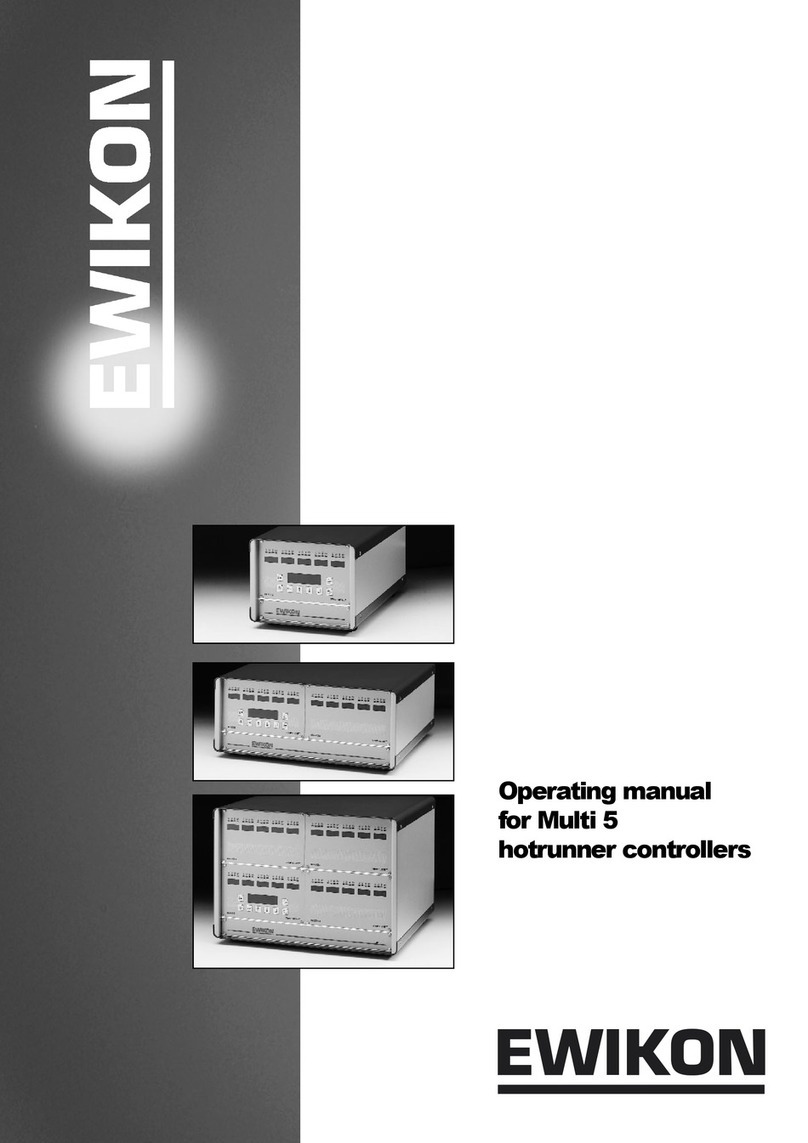
EWIKON HPS-C-TS User manual

HPS-C-TS
Hotrunner Controllers
Operating manual for
multi-zone controllers
with Touch-Screen-Control
Valid for all controllers with PC-control,
item number 68010.120,
from software version 1.8.0

HPS-C - TS operating instructions Page 2 / 32
Safety instructions:
Before working on the plant, ensure it is off-circuit. Unit switch OFF and disconnect mains plug.
Connection, repair and maintenance work may only be carried out by qualified skilled personnel.
Before putting into service the system is to be inspected in accordance with DIN EN 60204 – 1 (11/1998 - Safety of
machinery - electrical equipment) and the generally recognised rules of sound engineering practice. The connected
components can become very hot. Appropriate precautionary measures are to taken when putting into service and during
operation.
Scope:
This EWIKON control system can be used to operate EWIKON hotrunner systems in dry rooms in industry.

HPS-C - TS operating instructions Page 3 / 32
Contents
Safety instructions ....................................................................................................................................... Page 2
Features ........................................................................................................................................................ Page 4
Display elements and controls.................................................................................................................... Page 5
Connection and putting into service .......................................................................................................... Page 6
Operating the system................................................................................................................................... Page 8
•Introduction.............................................................................................................................................. Page 8
•"Display" menu....................................................................................................................................... Page 9
- Display
- Zone selection / Grouping
- Alarm messages
•"Table" menu .......................................................................................................................................... Page 11
- Display
- Zone selection / Grouping
- Alarm messages
•"Parameter" menu.................................................................................................................................. Page 12
- Display
- Zone selection
- Zone labelling
- Activate / deactivate zones
- Hotrunner operating voltage selection 5V/230V
- Operating mode
- Set value input (temperature / output power / current)
- Increase mode
- Decrease mode
- Zone status / error messages
Extended functions after entering password...................................................................................... Page 14
- Data recording (Level 1)
- Spare sensor (Level 1)
- Thermocouple (Level 1)
- Load type / control parameters (Level 1)
•"Chart" menu .......................................................................................................................................... Page 16
- Display
- Data printout
- Setting up the diagrams
•"Utilities" menu ...................................................................................................................................... Page 18
- Display
•"System" menu....................................................................................................................................... Page 18
Parameter settings ................................................................................................................................ Page 19
- Tolerance band monitoring
- Release delay time
- Limit values for tolerance band function
- Drying mode (Level 1)
- Startup ramp / heating-up speed (Level 1)
- Maximum increase time
System overview ................................................................................................................................... Page 20
- System information
- System status / error messages
Mould management............................................................................................................................... Page 21
•"Options" menu ..................................................................................................................................... Page 22
- Password entry
- Load type recognition / self-optimization
- Even heat up mode
- Temperature units
- Data backup
- Error log book
- Log book
- Windows interface
Specifications ............................................................................................................................................... Page 26
Connector pin and terminal assignment .................................................................................................... Page 28

HPS-C - TS operating instructions Page 4 / 32
Features
HPS controllers
•Adaptive PID control with self-optimization, facility for manual fine tuning
•Heating current monitoring in 230V operation, current control in 5V operation
•Setpoint ramps with freely selectable increase
•Intelligent drying mode with leakage current measurement
•Increase function (time-limited) for heating the control zones after starting up,
manually or via external contact
•Decrease function, manually or via external contact
•Load error detection for short circuit, interruption and partial load failure
•Thermocouple-error detection for short circuit, interruption or reverse polarity
•Multilingual display
HPS-C - TS touchscreen control
•Easy control of up to 160 control zones
•Grouping of related control zones
•Data storage facility for various mould settings
•Image viewer, e.g. for assignment and connection plans
•Error and event logging
•Protection of the critical settings and data through various access levels
•Data recording for overview and comparison (reference) diagrams
•Even heat up function for the whole hotrunner system
•Diagnosis function for mould start-up and checking

HPS-C - TS operating instructions Page 5 / 32
Display elements and controls
The PC version is controlled via 26 membrane keys arranged around the display and varying dialog boxes on the touch
sensitive screen surface.
No. Name Function
1 ON / OFF Switch the hotrunner system on and off
2 Increase Manual increase mode ON / OFF
3 Decrease Manual decrease mode ON / OFF
4 ALARM Open the alarm window with the currently queued alarm messages
5 Diagram Switch between display and setup in the chart menu
6 Cursor left Page / move left
7 Cursor right Page / move right
8 Cursor up Page / move up
9 Cursor down Page / move down
10 END Quit the program, shutdown PC or switch to Windows
11 SET Set value input via pop-up window
12 GROUP Carry out or open zone grouping
13 CLEAR Cancel zone grouping
14 PROG Open mould management
15 PRINT Open the print function (screen view or list)
16 F1 Special function, menu dependent
17 F2 Special function, menu dependent
18 HELP Online help
18
Zone window Menu selection via screen or corresponding function keys
11
12
13
14
15
16
17
1 5 6 7 8 9 102 3 4 Status ba
r

HPS-C - TS operating instructions Page 6 / 32
Connection and putting into service
Bedienteil, Art.-Nr.
68010.300
Regelgerät 24-fach 230V,
Art.-Nr. 68010.324
Bild BA_HECK.WMF
Geräteschalter
Anschlußstecker für
Thermo-Sammelkabel,
mit Stifteinsatz
Netzzuleitung mit
Anschluß-Stecker
Anschluß-Stecker für
Signalleitung 24C DC
Abschlußstecker mit
Buchseneinsatz
Abschluß-Stecker mit
Stifteinsatz
Anschluß-Stecker für
Kommunikationsleitung
zum Bedienteil
Anschluß-Stecker für
Kommunikationsleitung
vom Regelgerät
Typenschild
Anschluß-Stecker für
Signal-Geräte 230V
Anschluß-Stecker für
Anschlußkabel 230V,
mit Buchseneinsatz
Unit -
address switch
Control circuit
Fuse,
F 6.3A
8 or 4-zone
controller module,
top zone 1-12
bottom zone 13-24
Zone fuse,
F 12.5A
LEDs for status display
of the modules
(Power, mode,
error, increase and
decrease)
Control panel, Art No.
68010.300
Controller 24-zone 230V,
Art No. 68010.324
Display for 5V
or 230V operation
Numeric keypad
Function keys
Figure BA_FRONT.WMF
Controller 24-zone 230V
Art.-Nr. 68010.324
Control panel, Art No.
68010.300
Terminating resistor
connector with pin insert
Connection plug for
signalling devices 230V
Unit switch
Connection plug for
thermo bus cable,
with pin inser
t
Mains power cable
with connection plug
Rating plate
Connection plug for
communication cable
from controller
Connection plug for
signal cable 24V DC
Connection plug for
communication cable
to control panel
Terminating resistor
connector with socket
insert
Connection plug for
connection cable 230V,
with socket insert

HPS-C - TS operating instructions Page 7 / 32
The figures on the page on the left show an example of a 24-fold controller 230V with external control panel.
The PC control is connected analogous to the control panel, irrespective of whether it is realised as a controller
rack or wall-mounted device.
To avoid problems, the following procedure should be followed to start up the control system:
•Before connecting the equipment to the electricity supply the touchscreen monitor (TS) must be fixed to the swivelling
arm supplied. Depending on the model, this is mounted on the controller or must be installed in a suitable place on the
injection moulding machine. The grounding stud on the TS housing must be connected to ground with the PE
conductor cable on the unit's swivelling arm or via a separate PE conductor cable.
•Connect the communication cable at the TS and at the controller. Ensure that the connector at the second CAN
interface of the controller is fitted with terminating resistance (Art. No. 18096 with socket insert).
•Connect signal cable 24V DC to the controller and the injection moulding machine controls, if unit group functions
(decrease, fault messages, ...) are required.
•If necessary, connect addition signalling device 230V to the controller connector provided.
•Insert the controller's mains plug. Ensure that the power supply matches the data given on the controller's rating plate!
•Connect connection cable 230V to the rear of the unit and the mould or connection cable 5V to the front of the unit and
the mould. For 5V operation, also connect the ground cable to the mould and the controller, the assignment is
described in greater detail in the chapter "connector pin and terminal assignment“.
•Connect thermo cable at the rear panel of the unit and the mould.
•Switch on the unit switch on the rear panel of the unit (in several models also on the side panel).
•After switching on the Windows operating system starts first on the TS. Then the application program for operating the
HPS-C controllers is automatically loaded and run.
•After being switched on the TS checks the system configuration connected to the system bus and displays it. The last
used settings are then loaded. This process can take 1 to 2 minutes, depending on the number of control zones. After
the system has successfully started up the TS starts in the "Display" menu, depending on the system configuration, the
display is roughly as shown on page 5.
If problems occur while importing the system configuration, the following measures should be taken:
•If several controllers are connected to a touchscreen, the address switch of the controllers must be set (from 0 to 3).
The zones are consecutively assigned in the TS starting with unit "0". Maximum 4 controllers can be connected to a
TS; up to 160 zones are supported.
•Check whether the terminating resistor connector is fitted at the end of the communication cable (last unit).
•Check for secure fit of the interface cable at all connections and the condition of the cable (pinching along cable layout,
damage ...).
Further operation of the system and value inputs as described on the following pages.

HPS-C - TS operating instructions Page 8 / 32
Operating the system
Introduction
The HPS-C control system with control monitor is controlled using 26 surrounding keys and the corresponding buttons on
the touchscreen surface. All the settings for the control system can be entered in the various menus described in detail in the
following text. The buttons represented as tabs or the keys arranged directly above these (not shown in the figures) are used
to switch between the menus. After starting up the system the "Display" menu is displayed in which, if the basic configuration
is correct, all controller operations (switch on, switch off, set value changes, increase, ...) can take place.
The following settings can be set or adjusted in the various menus; detailed explanations are given in the following chapters:
•"Display" Operating the system, set value changes, display up to 40 zones per page as zone window
•"Table" Operating the system, set value changes, display up to 20 zones per page in tabular form
•"Parameters" Basic mould setting (activate zones, operating mode, setpoint, increase and decrease values, ...)
•"Chart" Graphic display of the process values (temperature, output power, output current)
•"Utilities" Image viewer for connection and wiring plans or mould drawings
•"System" Setting/Adjusting the system parameters, system status overview, mould management
•"Options" Password entry, special function selection, error log book, permanent data recording
To change set values, the relevant zones are selected in the "Display" and "Table" menus, after pressing the "SET" key the
input window appears on the screen. In the other menus, immediately after "touching" the value to be changed the
respective input window appears. Most values are entered using the number keypad and are accepted with "OK" or quit with
"ESC". Information about which value is being changed and in which range the entry can be made appears in the lower
information window.
Above the number keypad there are three buttons which can be used to choose whether:
•"Set value" the entered value is adopted as the new value
•"+ " the entered value is added to the old value
•"- " the entered value is deducted from the old value
The system status and other information are displayed in the bottom part of the screen:
•Hotrunner ON or OFF
•Status display
•Information display (e.g. ALARM)
•Operating voltage of the hotrunner system (5V, 230V or mixed operation)
•Status of each of the 4 digital signal inputs and outputs (assignment - see chapter: connector pin and terminal
assignment)
•Information about current and total available pages per menu, page using arrow keys
•Time or date, switchover by touching the display surface

HPS-C - TS operating instructions Page 9 / 32
"Display" menu
Display
After switching on and starting up the control system the program starts in the Display menu. Up to 40 zones per page are
displayed as single windows with the most important process information. If there are a larger number of zones (max. 160)
the other pages can be opened using the cursor keys. The number of available pages is shown in the pages information
display of the status bar. Active zones have white backgrounds; the set values can be seen. Inactive zones have a grey
background and are shown without display of the process values (exception: If a temperature sensor is connected the
measured temperature is displayed).
The most important process information per zone is displayed in the "single zone windows":
•Name of the zone within the hotrunner system, in order to enable faster assignment (e.g. "nozzle 1").
When delivered corresponds to the zone number, changes can be made in the "Parameters" menu.
•Actual value display with coloured background, to ensure quicker overview. The marking is dark blue, light blue, orange
or red depending on the difference between the actual and set value. The limits are deduced from the tolerance band
settings ("System / System parameters" menu).
•Set value with display of the units (°C, % or A), changes can be made using the "SET" key.
•Current output power, depending on 5V or 230V operation in "A" (amperes) or "%" (percent).
•Zone number as consecutive numbering in the whole control system.
•Output power as analog display (bar chart) in % of maximum output.
Active zone
Inactive zone
Status ba
r
Name
Set value
Zone numbe
r
Actual value with
coloured trend
display
Output power
(% / A)
Output power

HPS-C - TS operating instructions Page 10 / 32
Zone selection / grouping
The set value can only be adjusted in the Display menu if the relevant zones have been selected beforehand. The selected
zones are marked with a green frame, in order to enable them to be more quickly identified. Both single and several or all
zones can be selected or grouped.
The selection or grouping can be carried out in several ways:
•Selection of a single zone by touching the zone window.
•Selection of any combination of several zones by touching the corresponding zone windows. Only zones set in the
same operating mode ("°C" / "%" / "A“) can be selected together.
•Grouping of several consecutive zones. The first and last zones required are selected; all zones between these are
then also selected by pressing the "GROUP" key. This enables e.g. set value changes to be made for a whole nozzle
group.
•Grouping of all available control zones. The first and last zones of the control system are selected; the complete
selection can then be made using the "GROUP" key.
After all the required zones have been selected and grouped, the "SET" key can be used to open the input window and to
make the required set value change.
The zone selection / grouping is then individually cleared by touching the screen or is completely cancelled using the
"CLEAR" key.
If necessary the grouping can be retained. It is useful if e.g. to open single nozzles in a high cavity system with a higher set
value (" + " function in the input window) and must be removed again after starting up (" - " function in the input window). Any
differing set values of the zones are then reset to the basic setting.
Alarm messages
If errors occur and are detected by the control system the affected zones are displayed with a red frame to enable them to
be immediately recognised. In addition, an "ALARM" message is output in the status bar, so that errors in zones on any
other pages can also be recognised. After pressing the "Alarm" key or touching the alarm message the alarm window is
opened, in which all currently queued error messages are displayed in plain text. The alarm window can also be opened
from all other menus.
Corrected errors are acknowledged here in order to reset the alarm message. If sufficient information is available the window
is closed using the corresponding button.
All errors that have occurred since the control system was switched on are saved in the error log book of the control monitor
and can be opened under the "Options" menu.
Zone with error
display
Alarm window
Alarm message

HPS-C - TS operating instructions Page 11 / 32
"Table" menu
Display
Unlike the "Display" menu, all zones are displayed row by row in tabular form. Apart from the most important process data;
actual temperature, set value and output power, other values are also available. The display is intended as an alternative to
single window display and if the operator wishes can be equally used.
The following information per zone is displayed in the "Table" menu:
•"No" Zone number within the overall system
•"Name" Name of the zone
•"Temp." Current actual temperature value
•"Set value" Set value
•"Actual value" Current output power in % (230V operation) or A (5V operation)
•"Type" Operating voltage of the hotrunner: 230V or 5V
•"Controller" Operating mode of the zone: Temperature controlled (°C) or manually specified control variable
(% or A)
•"Current 230V" Maximum current through the heating conductor or input current of the 5V transformer
•"Increase" Set value for increase mode (setting in the "Parameters" menu)
•"Decrease" Set value for decrease mode (setting in the "Parameters" menu)
After selecting the required zones, however, only the set value can be changed in this menu.
Unlike the window display, in the tabular display of the progression of the process only 20 zones per page are displayed; the
scroll bar on the right-hand edge of the screen is used to page down.
Further, the actual value is not highlighted in colour if it differs from the set value.
Zone selection / grouping
Selection and grouping of zones and adjusting set values is carried out analogous to the "Display" menu. However, instead
of the zone window the corresponding row must be selected.
Alarm messages
The display of alarm messages and opening of the alarm window is analogous to the "Display" menu. However, instead of a
red frame faulty rows are completely highlighted in red.

HPS-C - TS operating instructions Page 12 / 32
"Parameters" menu
Display
The basic configuration of the controller for the respective application is set in the "Parameters" menu; information about the
zone status is also available here. The zone number, zone name, position within the control system and the operating mode
setting are displayed in the upper part of the screen. Below this there are two other separate areas. The basic settings for
temperature controlled or manual mode are entered in the left-hand side as well as setting the values for increase and
decrease mode. Further, the current actual values of the temperature and output power are displayed. The zone status
information is displayed in the right-hand area.
IMPORTANT: When entering and changing values, ensure that the required zone or group has been selected.
Zone selection
The zones to be changed are selected in the "zone number" field and this might be done in various ways:
•Select single zones for adjustment. These can be selected using the cursor keys or by pressing the button and setting
the then available slide control. Also, after touching the display field an input window appears, in which the zone
number can be entered directly.
•Adjusting a group of zones. The zones are grouped in the "Display" or "Table" menu using the method described; the
information "Group" appears in the display. The values of the first zone selected are displayed; all changes made are
applied to all the selected group members. This enables fast adjustment of specific zone groups, e.g. nozzles or
manifolds.
•Adjusting all zones. The selection is made using the slide control by moving it to the "all" position or by directly entering
the zone number "0". However, this is only possible if there is no more grouping ("CLEAR" key). This function is used
for quickly entering the basic settings of new moulds; however it is also useful for making changes which affect all
zones while the plant is running. The changed values are also applied to inactive zones.
Therefore, this function should only be used to activate zones in certain cases, as it activates ALL the zones in the
control system.
Zone numbe
r
Zone name
Position of the
zone within the
control system:
- Device number
- Module in the unit
- Zone number on
the module

HPS-C - TS operating instructions Page 13 / 32
Zone labelling
After touching the display field for the zone name the input window shown below appears. The zones are given explanatory
names (nozzle 1-n, manifolds 1-n ...) for faster orientation in a high cavity system. These names can be approx 10
characters long and are used in all the menus.
To automatically number several zones (select "Group" or "all"), the number of the first zone is entered followed by two dots,
as shown in the above display. The system then automatically labels the selected zones, e.g. from "manifold 1" to "manifold
8".
Activate / deactivate zones
The zones required for the connected hotrunner mould are activated using the corresponding button, whereby "yes = active"
and "no = inactive". The selected setting is shown "pressed down" (lighter).
Hotrunner operating voltage selection 5V / 230V
Selection of the hotrunner's operating voltage is zone-specific using the corresponding "runner type" button. For safety
reasons, this selection can only be made if heating mode is switched off.
Operating mode
The operating mode of each zone is set using the "controller" button. Depending on the selection made; "°C" = temperature
control or "%" = manual mode (in 5V operation correspondingly, "A" = current control) the basic settings values set apply.
Set value input
Depending on the operating mode, the input window is opened by touching the corresponding set value field. The required
set value is mostly dependent on the injection temperature of the material used.
Increase mode, value input
The increase value is a 2nd set value for the zone, in order e.g. to briefly set a short-term higher temperature level after
starting up to make it easier to open the nozzles. If the increase function is switched on the value entered is added to the set
value. The increase function can be switched on and off using the monitor's function key or the digital signal input.
Decrease mode, value input
The decrease value is a 3rd set value for the zone in order e.g. in the event of faults, to briefly set a short-term lower
temperature in the system to avoid damaging the material. If the decrease function is switched on, the value entered is
subtracted from the set value. The decrease function can be switched on and off using the monitor's function key or via the
digital signal input.
Zone status / error messages
Any zone errors that occur are reported in the "zone status" and are shown in plain text. Further, the zone's maximum
current measured by the controller is displayed, which makes it relatively easy to calculate the installed heating output:
Heating power P = voltage U * current I (whereby U equals the mains voltage, e.g. 230V)

HPS-C - TS operating instructions Page 14 / 32
Extended functions after password entry
After entering the correct password, experienced operators can also make further adjustments. The password is entered in
the "Options" menu and is described in the chapter with the same name. The additional functions displayed below are
available on the next higher access level (Level 1).
IMPORTANT: As the following settings may have serious effects on the operating and control behaviour, changes
should only be made by skilled personnel.
Access level "Level 1":
Data recording
If permanent data backup of the process values on the hard disk has been switched on in "Options", the required recording
data can be set here. To do this, the required zones are selected or grouped, after touching the actual value display field an
input window appears in which data recording can be switched on or off. This procedure must be separately carried out for
the temperature and control values. Further information about the "data backup" function is given in the "Options" chapter.
Spare sensor
No effect or function at present, reserved for subsequent extensions.
Thermocouple
The temperature measurement of the HPS-C controllers is designed for the connection of a thermocouple; in total 3 different
thermocouple types can be connected. When the units are delivered the type Fe-CuNi "L" according to DIN 43710 is set; the
types Fe-CuNi "J" and NiCr-Ni "K" according to DIN IEC 584 can also be used.
The setting and thermocouple type assignment is listed in the following table:
Selection Thermocouple Type Sleeve colour*) Plus leg*) Minus leg*)
"K" NiCr-Ni K Green Green White
"J" Fe-CuNi J Black Black White
"L" Fe-CuNi L Blue Red blue
*) Colour code of the thermocouple connection cable; deviations are possible.
S
p
are senso
r
Thermocou
p
le
Load t
yp
e
Data recording
Control parameter

HPS-C - TS operating instructions Page 15 / 32
Load type / control parameters
The HPS-C control system is equipped with a PID control algorithm, which ensures optimum control performance and small
deviations between the actual and set value during operation. During the system's heating phase other additional supporting
special functions act (ramp, compound operation ...), as the connected controlled system (hotrunner) mostly behaves
differently to the subsequent operation.
The controller usually determines the load type for each zone itself (see chapter: "Options - Load type recognition"), and
depends on the type of heating connected. In total, they are divided into 10 different types, for which respective specific
controller default systems are stored in the system. The following table gives typical values for the various settings, however
may contain different values in the controller:
Load type Hotrunner type P (amplification) I (Reset time) / s D (Rate time) / s
1 (230V) 230V, very sluggish performance 25.00 150.0 0.5
2 (230V) 230V, sluggish performance 20.00 120.0 0.4
3 (230V) 230V, average performance 15.00 90.0 0.3
4 (230V) 230V, fast performance 10.00 60.0 0.2
5 (230V) 230V, very fast performance 5.00 30.0 0.1
1 (5V) 5V, very sluggish performance 0.80 15.0 6.4
2 (5V) 5V, sluggish performance 0.80 15.0 6.4
3 (5V) 5V, medium performance 0.80 15.0 6.4
4 (5V) 5V, fast performance 0.80 15.0 6.4
5 (5V) 5V, very fast performance 0.80 15.0 6.4
If required the control characteristics can also be adjusted manually, if good control results are not achieved with the
automatic recognition. Either the load type can be changed, whereby the settings stored in the system are automatically
adopted. Optionally, the 3 control parameters can also be individually adjusted.
Proportional component P (amplification):
The amplification determines size of the set power depending on the control difference. Higher values mean a higher output
with the same deviation; lower values correspond to a smaller output. The proportional component mainly acts during the
start-up of new set values (large control deviation) and faults during operation, and corrects deviations as quickly as
possible.
Integral component I (reset time):
The reset time depends on the connected heaters and the speed with which the temperature can follow the changes in
output power. Sluggish heaters require a larger reset time, fast nozzles a correspondingly smaller time frame. The integral
component keeps the control circuit at the required set temperature via a summed (integral) output power, if there are no
longer any control deviations (control offsets).
Differential component D (rate time):
The rate time (derivative action time) counteracts changes and depends on how fast the actual value of the connected
heaters changes within a specific unit of time. A more or less large attenuation must be set depending on the speed of the
actual value change, in order to avoid control circuit oscillation. The differential component mainly acts in the event of fast
changes, e.g. cycle-induced faults due to frictional heat input, and determines (differentiates) its output power from the
change per unit of time.
The total output power for the control circuit is calculated from the three single components P, I and D.
IMPORTANT: The following points must be noted in case of manual intervention in the controls:
- The values should be changed individually and in small steps in order to enable differentiated
evaluation of the results. After each change the controller requires a certain amount of time
(approx 5 – 10 minutes) to adapt to the new settings.
- Manual settings are only permanently retained if load type recognition is switched off in the
"Options" menu. If not the controller default setting is loaded each time the hotrunner system is
switched on again.

HPS-C - TS operating instructions Page 16 / 32
"Chart" menu
Display
Apart from permanent data recording on the hard disk, 10 diagrams are available with touchscreen control, on which the
important process data and their curves can be shown. These can then be used to query the trend or peak values of the last
time interval. It is possible to plot up to 10 different values in each diagram. Therefore, in total 100 process values are
available. Each diagram can be given an easily understood name; the recorded (plotted) data is given in the key with the
corresponding colour. The diagram area scaling is shown on the left and bottom edge and depends on the settings entered
in the diagram setup.
The current diagram number is displayed in the status line instead of the page information. The cursor keys are used to
page backwards and forwards between the different diagrams.
The "Diagram" key is used to switch between diagram view and setup.
Data printout
If important diagram curves or settings are to be documented, it is possible to printout the current screen display. After
pressing the "PRINT" key the print window appears for selecting whether to print directly to an installed default printer or into
a print file.
A printer with a USB connection can be set up as the default printer using the Windows interface; this printer is then also
used by the operating program for the HPS-C controllers.
If a file printout is selected a bitmap file is saved in a subdirectory of the program path, this can then be transferred to
another PC via the USB port.
The windows interface is accessed in the "Options" menu and this is described in the chapter with the same name.
The procedure for printing out data is the same in all the menus; however, in the "Table" and "System" menus the output is
in list form instead of the screen view.
Setting up the diagrams
Before using a diagram it must be set up for the respective requirements. The setup page is opened by pressing the
"Diagram" key or by pressing the surface of the diagram. In setup the required diagram number is selected first from the top
left-hand side and if necessary an explanatory name is entered (e.g. "temperature zone 1 - 10").
Diagrams which have been set up can be reset to their original condition by pressing the "Reset" button (all settings reset to
default values and recording function switched off).
Name
Diagram area
Print window
Key
Chart number

HPS-C - TS operating instructions Page 17 / 32
The settings for the time axis (X-axis) of the diagram are specified in the "recording" field. The interval specifies the cycle in
seconds over which the data is recorded. The whole recorded duration of the diagram changes depending on the interval
time, e.g. "Interval = 5 sec Æduration = 1 h“, "interval = 10 sec Æduration = 2 h". The interval time can be set between 1
second and 1 hour (3600 seconds); the total duration varies accordingly between 12 minutes and 30 days. The "continuous"
button is used to specify whether the data is to be recorded once ("no") or continuously ("yes"). In the case of continuous
recording the diagram is "shifted on" accordingly at the end and the x-axis is relabelled, the oldest data is lost. In the event of
once-off recording a certain period is recorded after the unit is switched on then the diagram function ends.
The minimum and maximum value of the y-axis scaling is specified in the "Y-axis" area, changes can also be made during
the current recording.
The required process values for the diagram are set in the lower area; a maximum of 10 different values are available for
each diagram. First the input window is opened by pressing the corresponding button, then the required zone or zone
number is either entered directly or selected by opening the sliding bar. Then the appropriate buttons are pressed to set the
required process value, to be recorded for this zone (e.g. "temperature - actual value" or "output power - set value“). The
settings are accepted with "OK" or discarded with "ESC".
After all the required zones to be recorded have been set for the diagram, data recording is switched on. After this only the
Y-axis scaling of the selected diagram can be changed, all other fields which can no longer be changed have a grey
background.
If necessary, other diagrams can be set up. The "Start all" and "Stop all" buttons can be used to switch recording on or off for
all the diagrams set up.
If the program is quit using the "END" key, the most recently recorded data of all active diagrams is backed up as a bitmap,
this bitmap is then available for viewing in the "Utilities" menu when the program is restarted.
To save memory space, this data is overwritten with the current values each time the program is quit.
Use the "Diagram" key or the "OK" button to return to the diagram view.

HPS-C - TS operating instructions Page 18 / 32
"Utilities" menu
Display
A simple image viewing function is provided in this menu with which the graphic diagrams can be displayed in BMP or JPG
file format. This enables mould views, wiring plans or other mould data to be directly saved on the PC. If necessary this
information is then available to the user "online". The graphic files must be stored in the "Images" subdirectory of the
program directory so that they appear in the file selection window after the program is started. Further information on access
to the Windows interface is given in the "Options" chapter. Further, if diagram recording (plotting) is active the most recent
process data is stored as graphic diagrams: "Diagram1" to "Diagram…" when the program is quit. When the program is
restarted this information can then be evaluated or printed out as required.
A window section of 640 * 480 pixels (VGA format) is available for the image area, if the graphic images are larger or
magnified only a part of them are displayed.
The "Zoom in", "Zoom out", "Original size" and "Window size" buttons can be used to adjust the graphic display to the
respective needs. If the display or graphic is enlarged (zoomed in) with more than 640*480 pixels the window section can be
moved in the corresponding direction using the cursor keys.
"System" menu
In the "System" window the menu is divided into 3 further submenus, in which all general settings applicable to all zones
can be entered or adjusted for the whole control system. The required menu in which the values are to be changed or
information queried is selected using the corresponding buttons in the bottom part of the screen.
The following options are available to choose from:
•"System parameters" Set parameters and limit values or switch functions on and off
•"System survey" Display the connected units and modules, information about the respective operating status
•"Moulds" Save or load mould settings
A more detailed description of the individual submenus is given in the following sections.
Selection
window
Image area,
640 * 480
p
ixels
ZOOM switch

HPS-C - TS operating instructions Page 19 / 32
Parameter settings
Values and functions which apply across the zones to all the controller modules can be changed or switched on and off in
this submenu. Access is also divided into different authorisation levels, which are protected by a password. Password entry
and access management are described in greater detail in the "Options" chapter.
The following screenshot shows the values, which can be changed in access levels "Level 0" and "Level 1".
Tolerance band monitoring
The tolerance band function enables automatic monitoring of the injection moulding process for compliance with the entered
set values. Tolerance band windows can be entered for the temperature and current control; these then apply to all
connected control zones. The monitoring function can be used in the data network with the injection moulding machine to
trigger various reciprocal actions, e.g. decreasing the hotrunner in the event of a machine fault or interruption of injection
operation if faults occur in the hotrunner system. However, this requires a connection between the controller and the
machine, e.g. via the signal cable 24V, Art No. 60070.019. Alternatively, or in addition, an optical or acoustic signalling
device can be connected to the connector 230V. The pin assignment is described in the "connector pin and terminal
assignment" chapter.
Release delay time
This is used for delayed switching off an error message in case of tolerance band deviations, in order to allow the hotrunner
system sufficient time to develop an adequately stable thermal condition after the heating up phase.
Limit values for tolerance band monitoring
In the tolerance band function there are two pairs of values available for the temperature and current monitoring. The inner
pair of values is intended for setting a warning limit if the process data only slightly differs from the set value specifications.
This enables problems to be detected early. The outer pair of values is used to generate fault messages if the current
process data deviates a lot from the specified set value. The warning and fault messages can be picked off via separate
outputs at the controller.
The settings act relative to the set value, i.e. if e.g. "Upper warning limit = 5°C" and "Lower warning limit = 5°C" a warning
message is issued for deviations of > ±5°C from the set value. The advantage here is that if the set temperature or various
settings of the different zones change the limit values do not have to be adjusted.
Drying mode (Level 1)
The starting operation of 230V heaters is always followed by a drying phase in order to remove any residual moisture in the
hotrunner system. The HPS-C control system operates in phase-fired mode, in order to avoid damage to the connected
heating loads. Compared to the pulse packet mode used in normal operation, in phase-fired mode smaller peak voltage
values are connected to the heating conductor so that arcing due to moisture can avoided. During the drying phase, all 230V
heaters are controlled with an adjustable maximum power (max. output power) for a minimum period (time for drying out)

HPS-C - TS operating instructions Page 20 / 32
and at a maximum temperature (start-up temperature), after this the system starts with the set set-point value.
The drying phase is prematurely aborted if:
•The leakage current measurement detects there is no moisture in the hotrunner system.
•All temperature values in the hotrunner system were over 120°C when the system was switched on.
Startup ramp / heating-up speed (Level 1)
When the hotrunner system is switched on or in case of set value changes, the set gradient determines the speed (change
per second), with which the system is to change to the new set value. Therefore it is possible to influence the heating-up
speed of the hotrunner system. However, when setting this value it is necessary to consider that by virtue of their physical
properties sluggish heating loads, e.g. manifolds, cannot achieve fast changes e.g. to the temperature.
Maximum increase time (Level 1)
Increase mode has a maximum time limit in order to avoid material damage in the hotrunner system due to a continuously
too high temperature level. After the set time has expired, increase mode is automatically discontinued, if it was not
previously quit manually or via the external signal input. The setting "0 seconds" switches off the maximum time limit function
for increase mode.
System survey
The system survey provides a tabular display of all controllers and modules connected to the operator's control unit with the
corresponding zone assignments in the whole system. Further, the installed software versions of the individual modules are
displayed as well as their status display. If system errors have occurred, the relevant column is marked red so that the
module concerned can be immediately localised. The "System status" button in the status bar also has a red background if
an error occurs.
The "System overview" menu can also be opened by touching the system status button on the screen.
System information
•"Device" Unit (device) number of the controller within the whole system
•"HPS-C" The module's address on the CAN bus
•"Channel" Arrangement of the control zones, zone numbers of the module
•"FW Vers" Software version of the module
Table of contents
Other EWIKON Controllers manuals

