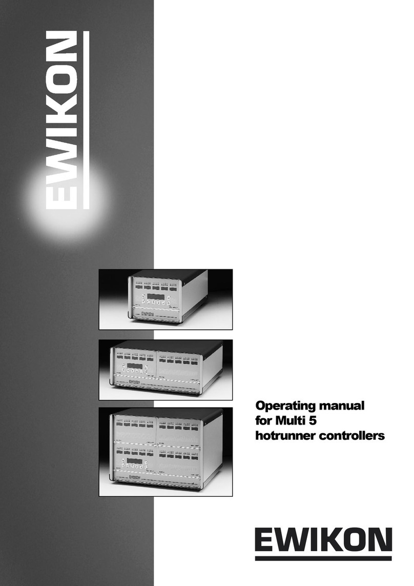
EWIKON HPS-C-E User manual

Valid for
item numbers:
66010.001 (1-zone)
66010.002 (1-zone)
67010.024 (4-zone)
67010.026 (6-zone)
67010.028 (8-zone)
67010.012 (12-zone)
HPS-C-E
Hotrunner Controllers
Operating manual

2
Analog control system 5 V
Contents
General safety notes 3
General technical data 3
Dimensions/Weights/
Connection and Power 4
Summary 5
Operation 6
Components of
the controllers 7
Start up 10
Terminal pin-out 10
Description of faults 13

3
Analog control system 5 V
General safety notes General technical data
Disconnect before working on the controller.
Mains switch most be OFF and plug disconnected.
Connection, repair and maintenance by
qualified staff only!
Before start up the controller must be checked
according to EN 60204-1:1992 or general rules
of engineering.
The power supply of the controllers should be
connected with the heating of the machine.
If the heating is switched off automatically, the
hotrunner system is likewise switched off then.
The connected parts may be hotter. Please take
all necessary precautions before starting the system.
The fan, air ducts and electronic components
should be cleaned in intervals of 3 to 6 months
(depending on pollution).
Cables, plugs and contact springs should be
checked and - if necessary - cleaned or
exchanged periodically
Field of application:
This EWIKON controller can operate our
5V hotrunner systems in dry industrial rooms.
CE declaration
The contriollers correspond to the
following standards:
DIN EN 60204-1 (11/98)
DIN EN 60742 (09/95)
EN 50081 and 50082
General technical data:
230/400V +6 / -10 %, 50 / 60 Hz
Protective system:
IP 33
Power output:
5V AC / 125A each zone
Thermocouple:
FeCuNi Type L
Decrease:
With a potential free ( NO )
relay contact in the machine.
Malfunction:
When there is a malfunction of the hotrunner system,
the cycle can be interrupted by a potential free
contact ( relay 250V/2A).Anoptical or acoustic
alarm announces the malfunction.
Temperature control:
PID with soft start:
The optimum control characteristic is achieved
with a phase proportioning control.
Operating range:
Amperage control: 10 - 125 A
Decreasing: 0 - 49 A
Thermocouple control:
90 - 399 °C
Decreasing: 0 - 99 °C
Environmental conditions:
0-50°C
Fault code
1 = Operating fault
2 = Excess current
3 = Disconnection
Broken fuse
4 = Triac defect
6 = Thermocouple defect

4
Analog control system 5 V
Dimensions, Weights,
Connection values, Power
Zone No. a mm b mm c mm kg Power
1 66010.001... 365 180 435 14 625 VA
1 66010.002... 365 180 435 14 625 VA
4 66010.024... 315 613 570 55 2.50 kVA
6 67010.026... 315 1015 570 82 3.75 kVA
8 67010.028... 315 1015 570 100 5.00 kVA
12 67010.012... 620 870 570 152 7.50 kVA
Version Mains wiring Power supply Mains plug
D - 230 Volt Schuko 16A
E - 240 Volt Schuko 16A
J - 208 Volt without
U - 240 Volt USA - Standard
B - 230 Volt without
Version Mains wiring Power supply Mains plug
D Y Star 230 Volt CEE16A
E Y Star 240 Volt CEE16A
J∆Delta 208 Volt without
U∆Delta 240 Volt USA - Standard 20A
B∆Delta 230 Volt without
Type:67010.026... / 67010.028... / 67010.012...
Type: 66010.001... / 66010.002... / 67010.024...

5
Analog control system 5 V
Summary
bt007-11

6
Analog control system 5 V
Operation
bt007-12
Combined module 60040.009
01: Green control light:
Operating indicator
02: Red control light:
Module defective
03: Red control light:
Defect in one ore more
control modules
04: External signal source
for decreasing current
to all control modules.
When active the red
light in the push button
is on.
05: Push button for
decreasing
06: Output fault
SR-Module 60040.011
01: Digital indicator of actual temperature
in amperes or °C
02: Set-value switch for setting of requirement
current in A or temperature in °C.
03: Set-value switch for adjustment of
current decreasing value in ampere
or temperature in °C
04: ON/OFF switch to separate the
SR-modules from the power modules.
05: Green control light as operation indicator
for mode “amperage control”. Input and
output data in A (Ampere).
06: Green control light as operation indicator for
mode “themocouple control”. All input and
output data in °C. When switching the
module on, the display flashes until the set
temperature is reached. Production can be
started after this optimization phase only.
07: Red control light as fault indicator. Fault
code appears in left portion of the display
(No.1):
1. Operating fault
2. Excess current
3. Disconnection
4. Triac defect
6. Thermocouple
defective
If during production a
thermocouple fails, the
module shows “fault”.
By switching the module
off, setting a current
value, and switching
the module on again,
production can continue.
The hotrunner system
continues operation in
“amperage control”
mode.
bt007-13

7
Analog control system 5 V
Components of the controllers
bt007-05
bt007-14
01: Combined module
02: SR-modules
03: Binding post 5V
connection
04: Thermocouple
connection zone 1
05: Main switch
06: Fuse T10A
07: Power cable
08: Circuit breaker
09: Thermocouple
connection
Zones 1-8

8
Analog control system 5 V
Components of the controllers
bt007-15
01: Combined module
02: SR-module
03: Binding post 5V
connection
04: Thermocouple connection
Zone 1
05: Main switvh
07: Power cable
08: Circuit breaker16 A
09: Thermocouple connection
Zones 1-8

9
Analog control system 5 V
01: Combined module
02: SR-module
03: Binding post 5V
connection
04: Thermocouple
connection zone 1
05: Main switch
09: Themocouple
connection
Zones 1-12
Circuit breaker is
positioned inside
the controller.
Remove top of case.

10
Analog control system 5 V
Start up
Hotrunner 5 V
Connect the thermo collective cable or the
thermo cable for zone 1.
Connect power cable.
Check that all connections are fastened tight.
Otherwise the components can be damaged
due to the high output current.
Heat up each zone seperately for a short while
to check if the power- and thermocouple zones
are assigned properly.
For operation of modules see page 6.
Terminal pin-out
bt007-17
Power case

Analog control system 5 V
Zone + red - blue
1 1 + 9
2 2 + 10
3 3 + 11
4 4 + 12
5 5 + 13
6 6 + 14
7 7 + 15
8 8 + 16
9 17 + 25
10 18 + 26
11 19 + 27
12 20 + 28
Thermo connection
Plug with pin insert
bt006-09
Pin assignment of the
socket-error signal
1 (-) blue (Konstantan)
2 (+) red (Iron)
bt007-18
Connection
11

Analog control system 5 V
12
Pin assignment
of decreasing socket
Pin assignment
of the socket-error signal
bt002-05 bt002-06
A: Decreasing socket
B: Machine or
C: Limit switch
1 + 2 : Potential free (NO)
relay contact of the
machine or limit
switch with NO
contact.
3: Vacant
In case of malfunction of the machine the
decreasing of all zones can be activated.
Decreasing is active as long as the contact
remains closed.
Attention!
Do not connect other voltage.
Connecting cable external decreasing,
lenght 3m, with plug (No. 10694)
A: Socket-error signal
Potential free (NO + NC)
contact of the single zone
controller. Max. power 2A/250V
1 + 2 : Closed in case of fault, hotrunner “OFF”
or power supply failure.
2 + 3: Closed under all other
operating conditions
In case of a malfunction of the hotrunner system
and in case of disconnection from mains a signal
can be given to the injection moulding machine
(e.g. machine STOP or an optical or acoustical
signal).
Connecting cable fault registration, lenghts 3m,
with socket (No. 10693)

Analog control system 5 V
13
Fault description
In case the module recognizes a fault, the zone
or the controller is switched off.
The fault code is displayed in the left segment
of the actual value display.
Fault codes:
Display in the SR-module (left display segment)
1 Operating fault
Check setting values
2 Excess current
Check connections and
cables
3 Open circuit or fuse
Check cable and electrical
connection, check fuse
4 Triac defect
Exchange module
6 Thermocouple defective
Check thermocouple and
connections


EC - Declaration of Conformity
We hereby conrm that the products described below conform to the essential protection requirements
of the following European Directives
2006/95/EC „Low Voltage Directive“
and
2004/108/EC „EMC directive“
with respect to their design type. This requires that the products are used for their intended purpose
and that the assembly and operating instructions are observed.
Alterations made to the product will void the declaration of conformity.
Producer: EWIKON Heißkanalsysteme GmbH
Siegener Straße 35
35066 Frankenberg / Germany
phone: +49 (0) 6451 / 501-0
Product: HPS-C-E hotrunner controllers for the operation
of 5 V hotrunner systems - analogue control system
Type: 66010.001 ; 1-zone controller without combined module
66010.002 ; 1-zone controller with combined module
67010.024 ; 4-zone controller
67010.026 ; 6-zone controller
67010.028 ; 8-zone controller
67010.012 ; 12-zone controller
Applied standards: DIN EN 61010-1: 2011-07 “Safety requirements for electrical equipment for
measurement, control, and laboratory use - part 1”
DIN EN 61000-6-2: 2006-03 “Immunity for industrial environments”
DIN EN 61000-6-4: 2007-09 “Emission for industrial environments”
Note: It is necessary to use genuine connecting cables outside the device to meet
the requirements according to DIN EN 61000-6-2 and DIN EN 61000-6-4.
Frankenberg, 02 April 2012
Dr. Peter Braun
Managing Director

EWIKON
Heißkanalsysteme GmbH
Siegener Straße 35
35066 Frankenberg
Tel: (+49) 64 51 / 50 10
Fax: (+49) 64 51 / 50 12 02
www.ewikon.com
tem number: 13820E Technical information subject to alteration. EWIKON 06/2013
Table of contents
Other EWIKON Controllers manuals
