4
The HPS-C-SLOT+controller is shipped
to the customer so that no setup work is
required for basic operation. Set points
in automatic and manual may be entered
and the zone will be controlled by turning
“On” the power. Many customers require
advanced features to satisfy their opera-
tion. This page will describe the basics
of “Advanced Setup”. Please note that
security level codes are not standard.
To place security on the HPS-C-SLOT+
controller you must activate security by
selecting your own personalized security
codes (network module required).
Advanced Setup Why Standby?How to Activate Alternate Standby Inputs
Why Boost?How to Boost How to View All Zones Quickly
General Troubleshooting – Turn “Off” Main Disconnect
Basic Troubleshooting
Advanced Setup Guide - Level 2 Security to Change
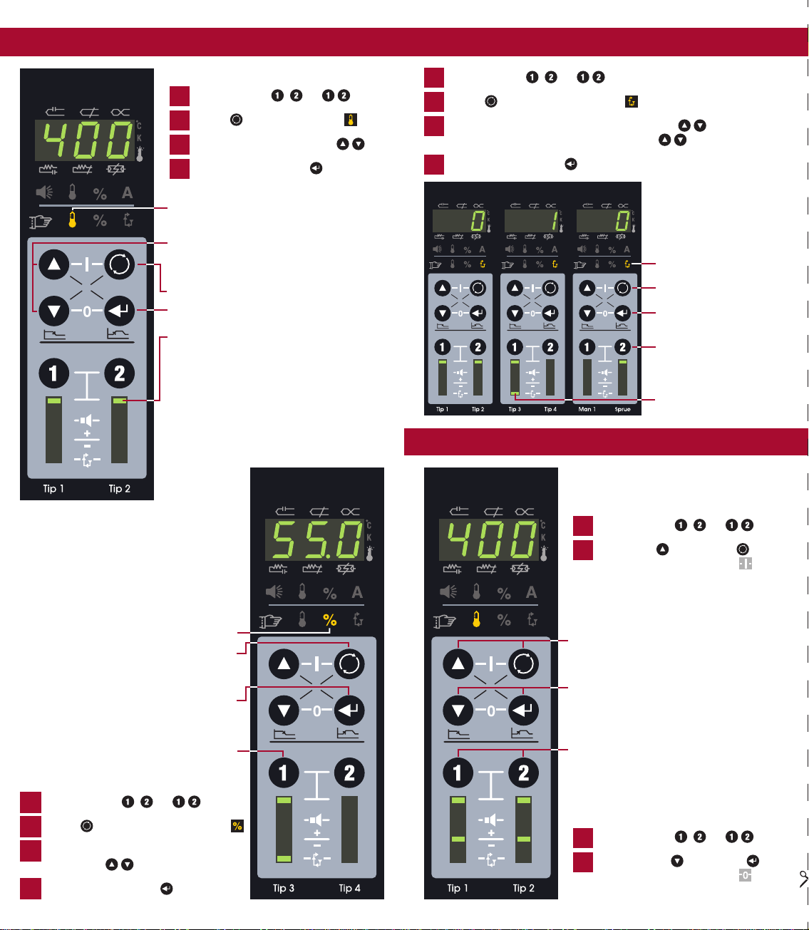
Advanced
setup
number
Press
“Select”
and “Enter”
together
Advanced
setup
setting
Press “Select”
and “Enter”
together
again
Toggle
between
number and
setting
Press
“Select”
to exit
advanced
setup
Alarm
status
Select
Zone
select
Select zone(s) to put into standby ,
or . Press “down” and
“select” together
The selected zone(s) will
go to the standby temperature
Hotter zones will cool to the
standby temperature
Colder zones will heat to
the standby temperature
Automatic zones = 220 ºF/104 ºC (default)
Manual zones = half of the manual set point
The outer decimal points will ash
during standby
To cancel standby,
press “down” and “select” together
The original standby source must be cancelled
to clear standby. Please reference alternate
standby inputs, shown to the right
Select zone(s) to boost ,or
Press “up” and “enter” together
Enter boost amount . Press enter
Zone(s) will boost 36 ºF/20 ºC (default)
for 120 seconds (default)
The 7 segment display will ash during boost
To cancel boost,
press “up” and “enter” together
1Tip 1 – in alarm, select zone
Select alarm status
Thermocouple open
2Tip 2 – normal operation
Zone is on, in automatic
and at or near set point
3Tip 3 – in manual,
Thermocouple may be open
Module applying a constant
% output to the heater
4Tip 4 – in automatic,
High temperature alarm
(+20 ºF/11 ºC default)
5Man 1 – normal operation
6Sprue – low alarm
Boost temporarily raises a zone(s)
temperature (typically tips) to clear
a cold slug on start up.
Some processors like to maintain a
lower set point on command for all zones
while they are working on something.
Standby switch on enclosure
(if available) all zones go to standby mode
Standby
input
• 24 or 120 VAC/VDC input
to activate
• All zones go to standby mode
(network module required)
• Standby button from
external software
• Selected zone(s) go to standby
mode (network module required)
Thermocouple pinched - The T/C is pinched
or the controller thinks it is pinched.
(Default: ≥9% output, must see +20 ºF/11 ºC
in 5 minutes). True pinch - the T/C is sensing
the temperature further away from the heat
source than intended. Without alarm, tem-
perature reads low, controller applies power,
runaway heat.
Thermocouple (T/C) open - the T/C connection
is broken, follow general troubleshooting.
Open heater - The heater connection is broken,
follow general troubleshooting.
Shorted heater - The heater is shorted or
exceeds the maximum rating of the module,
follow general troubleshooting.
Open fuse - fuse on module bad. Turn “Off” main
disconnect. Remove top cover, locate module,
check all fuses (4 per module, 2 per zone).
Thermocouple reversed – The T/C connection is
wired + to - at some point. Visually inspect each
connection. Make sure that only wires
of the same colour are connected.
Critical over temperature – The temperature
of a zone exceeded the alarm limit. (Default:
779 ºF/415 ºC). Both zones on the module
shut “off” automatically. To clear the alarm,
select alarm status and press enter. Noted by
vertical indicator segment.
Uncontrolled output – The module has an
unregulated output. Both zones on the module
shut “off” automatically. To clear the alarm, select
alarm status and press enter. Noted by vertical
and horizontal indicator segment (shown).
Over-Voltage – The module line
voltage exceeded 20 VAC for
1 minute (informational only).
1Check resistance from pin to pin, at the mold. T/C should read 3 – 50 ohms at room
temperature. Heater should read greater than 16 ohms. If there is no continuity
(open line) = broken connection, open heater or open T/C.
2Check resistance from pin to ground, at the mold. Heaters only – no continuity
(open line) = good. Some resistance is bad, heater shorted.
3Reattach the cable to the mold, detach the cable from the controller.
Check resistance from pin to pin on the cable. T/C should read 3 – 50 ohms at
room temperature. Heater should read greater than 16 ohms. If there is no continuity
(open line) = broken connection, open heater or open T/C. The connection is broken
in the cable set or the connectors/pins are not making contact.
4Reattach the cable to the mold, detach the cable from the controller.
Check resistance from pin to ground on the cable. Heaters only – no continuity
(open line) = good. Some resistance is bad, heater shorted. The wires are either
shorted in the cable set or the connectors are shorted to ground.
5At this point if everything is ne, the problem is in the controller. (1) turn “Off”
main disconnect, (2) locate problem module, (3) check fuses on module,
(4) swap bad module into a known good location, (5) turn “On” main disconnect,
(6) test the zone. If the problem follows the module = bad module. If the alarm
stays with the original zone, the problem is between the module and the
connectors on the rear of the enclosure.
6If the problem is not explained, or you need spare parts please contact:
1
1
2
3
3
2
13
13
12
12
14
14
10
10
11
11
9
9
5
5
4
4
7
7
6
6
Output module
Module thermocouple/
communications cable
Module power input/
output connector
(base of module)
Input power cable
Main disconnect (circuit breaker)
Thermocouple input connector
Power output connector
Auxiliary input/output connector
Enclosure link connector
Communications port
Ground stud
Fan
System wide standby switch
(on front)
Capacitors
# Limit (default) Explanation
(0) 0 – 4 (0) Power Priority™. 0 = (off). 1 – 4 = increased smoothing of power output. A = Power Priority™ is active (setup number)
(1) 0 – 999 (0) * Reset advanced setup to default values – enter 321; press enter to conrm
(2) 0 – 100 ºF/55 ºC (20 ºF/11 ºC) Temperature deviation alarm set point (individual)
Actual temperature activates individual zone alarm at this amount +/- set point
(3) -31 to 27 (0) Control algorithm adjustment (individual). 0 = auto selection. To view actual tuning value select code 4
Manual Selections: 10 to 17 fast tuning with increasing lag. 20 to 27 slow tuning with increasing lag
-17 to -10 fast manifold tuning with increasing lag. -27 to -20 very fast tuning with increasing lag.
-30 and -31 ultra fast low mass tuning. P = auto selection tune performed (setup number)
(4) -31 to 27 (none) Algorithm set point (view only). View auto tuning selection or manual tuning value
(5) 0 – 932 ºF/500 ºC (220 ºF/104 ºC) Standby set point (individual). When standby is activated, all automatic zones selected will control to this set point
Entering “1” will inhibit the module (both zones), when activated the relays will open, turning “off” the module power
(6) 0 to 54.0 minutes (5.0) T/C pinched detection time (individual)
9+% output, 20 ºF/11 ºC in 5 minutes – default. Change alarm timer amount. 0 = disabled
(7) 32 – 999 ºF/0 – 537 ºC (779 ºF/415 ºC) * Critical over temperature alarm. To clear the alarm, select alarm status and press enter
If this temperature is exceeded for seconds both zones turn “Off”. Max. 999 ºF (537 ºC) = disabled
() 32 – 932 ºF/0 – 500 ºC (752 ºF/400 ºC) * Automatic set point limit. The maximum set point an operator can enter in automatic on both zones
(9) 0 – 99.9% (99.9%) * Manual set point limit. The maximum set point an operator can enter in manual on both zones
(10) 0 – 999 ºF/537 ºC (100 ºF/55 ºC) * Boost limit. The maximum amount of degrees an operator can raise or lower the zone(s) during a boost
(11) +/-99 ºF/55 ºC (36 ºF/20 ºC) * Initial boost set point. Amount of degrees added to automatic set point, module adjustable within the boost limit
(12) 0-999 seconds (120) * Boost time set point. The amount of time boost is active
(13) 0 or 1 (0) * Degree F or C selection. 0 = “degree F”; 1 = “degree C”
(14) 0 or 1 (0) * Type J or K thermocouple selection. 0 = “type J”; 1 = “type K”
(15) 0 or 1 (0) * Zone power status on power up. 0 = all zones turned “Off”; 1= zones “On” when shut down last, stay “On”
†(16) 0 or 1 (0) * Enable slaved power-up. 0 = “Off”; 1 = “On”. All zones heat within 20 ºF/11 ºC of one another until set point
†(17) 0 – 999 (none) * Security code level 1. You must be in level 2 to change. Refresh procedure available, call EWIKON
†(1) 0 – 999 (none) * Security code level 2. You must be in level 2 to change. Refresh procedure available, call EWIKON
(19) - - - Output module controller software version/revision number (display only), select zone, version/revision displayed
(20) - - - Temperature controller software version/revision number (display only), select zone, version/revision displayed
(21) 0 (0) LED test. To activate enter 0. Turns “On” all LED’s for troubleshooting
†(22) 000 – 999 (level 2) Security level indicated. 0 = lockout; 1 = operator; 2 = supervisior. 0 - enter, drops one level
Elevate one security level at a time with your customized code
† Network module required * Network module distribution or value applies to both zones on the module
EWIKON Heißkanalsysteme GmbH
Siegener Straße 35, 35066 Frankenberg
Tel: +49 (0)64 51/50 10 ∙ Fax: +49 (0)64 51/50 12 02
Set individually by zone 1
2 3
G