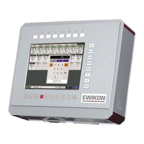
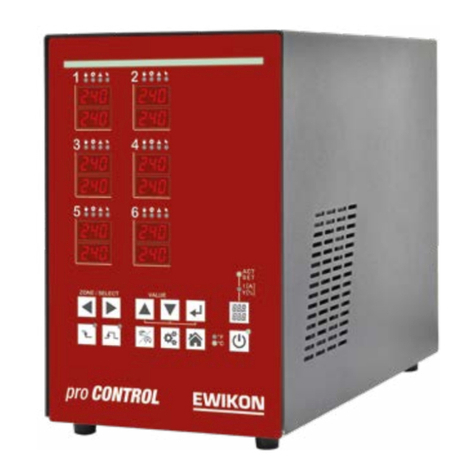
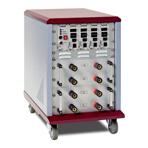
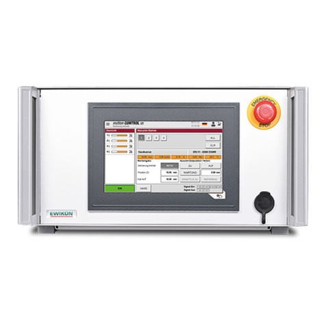
EWIKON Multi 5 User manual

Operating manual
for Multi 5
hotrunner controllers

2
Table of Contents
General Information
Safety Instructions........................................................ 3
General Instructions......................................................3
Controller
Start-Up..........................................................................4
Front Panel....................................................................4
Setting Setpoints & Activating Control Zones...............5
Function Keys...............................................................5
Alarm Indicators............................................................6
Programming Menu.......................................................6
Changing Settings.........................................................7
Soft-Start Ramp............................................................ 7
Manual Mode................................................................8
Specifications
......................................................................................9
Connections
Alarm Connector........................................................... 9
10-Pole..........................................................................10
24-Pole..........................................................................11
Important operating instructions! Read carefully!

3
Safety Instructions
- Please read these Operating Instructions carefully prior to using your EWIKON Multi 5 controller!
- Always withdraw the mains plug before performing any service work on the controller, particularly before opening the housing.
- Always disconnect the controller from the mains before replacing fuses.
- Before inserting the mould cables, be sure to verify that all connectors have been properly connected (see "Connections").
- Check power cord and mould cables for potential defects at regular intervals! Replace cable if the cable sheath is found to
be in any way defective!
General Instructions
- For each load (nozzle or manifold) to be connected, a separate control zone is required.
A "control zone" comprises a temperature sensor input and a load output including a fuse.
- When connecting the mould cables, be sure to assign them to the correct connectors. When viewed from the front,
the control zones are counted from left to right, starting at the bottom (see "Connections").
- Unused control zones must be switched off.
- For the load circuits, a heat-resistant flexible cable must be used for connection. For the temperature sensors,
a special compensating lead is required (see "Accessories”)!

4
Start-Up
After verifying that all cables are intact and have been properly connected, connect the mould to the controller.
If required, a connection can also be made to the machine by using the optional alarm connector. Connect the
mains cable to the power supply, then switch on the controller by means of the main switch located on the rear panel.
Select the desired setpoint. Note that all unused control zones must be switched off
(see "Selecting Setpoints & Activating Control Zones").
The controller now begins to heat up the mould in a uniform manner, thereby drying any heating elements that
may still be moist. During this process, the "temperature alarm" indicator lights will be flashing for all active zones
(soft-start-ramp). In the corresponding zone windows, the temperature (actual value) will be displayed in °C, while
"OFF" is indicated for all switched-off modules.
Upon reaching the pre-set temperatures, the production process can be started on the basis of factory settings.
Should an error occur during the start-up procedure, the cause of the trouble will be indicated by the indicator
lights of the respective zone (see "Alarm Indicators").
Front Panel
Alarm indicators Dialog window
Zone window
Heating pulse indicator
- lights up simultaneously
with power output
BOOST
button
Button indicator
STANDBY
button
PROGRAMMING/ENTER
button
UP/DOWN
button
CANCEL PROGRAMMING
button
SETPOINT
button
LOAD CURRENT
button

5
Setting Setpoints & Activating Control Zones
Button Command Display / Result
Display setpoint Upon pressing this button, the setpoints are displayed in the zone
windows of the active zones (or "OFF" for the non-active zones).
The button indicator lights up.
Zone identification "ALL" appears in the dialog window and the respective zone number is
indicated in the zone windows.
Select zone The selected zone is indicated in the dialog window, or
"ALL" is displayed for all zones.
2 x Confirm zones "TEMP" is displayed in the dialog window and the set to
be changed setpoint values are flashing in those zone
windows where changes are to be made (all in case of "ALL").
Set setpoint Modified setpoints are flashing.
Setpoint "OFF" deactivates the respective zone!
Store * The changed setpoints are stored in the system's
memory and displayed statically in the zone window; the
dialog display goes out.
Setpoint OFF The actual values are now displayed in the zone
windows of the active zones, and "OFF" for all
non-active zones.
* Exit programming without storing:
Cancel The unchanged setpoint values are displayed in the
zone windows, while "OFF" is displayed for all
deactivated zones.
Function Keys
Button indicator lights up upon activation of respective button ("ON").
Display setpoint The setpoints are displayed in the zone windows of all
active zones, while "OFF" is displayed for all non-active
zones.
Display load current The actual load-current value is shown in the zone
windows of the active zones.
Boost function active Increases temperature temporarily.
(also externally via alarm connector)
Standby active Decreases temperature permanently.
(also externally via alarm connector)
I/O
I/O

Alarm Indicators
Earth fault
Lights up if the heating-element-to-earth resistance drops below 100 kW, the power supply is
interrupted two-pole in addition.
Thermocouple
Lights up in the event of sensor breakage; at the same time, "- - -" is shown in the zone window. In automode,
the information displayed alternates between " - - - " and " - A - ". This indicator also lights up if polarity reversal has
occurred. In this case, the room temperature is displayed in the zone window.
Temperature deviation
Flashes during the heating-up phase of the soft-start ramp. Lights up continuously if the temperature exceeds or falls
below set limits (see "Changing Settings"). In case of overtemperature, the power supply is interrupted two-pole in
addition.
Overcurrent
Lights up if the set maximum value is exceeded (see "Changing Settings") or a load error occurs. In case of overcurrent,
the power supply is interrupted two-pole.
Programming Menu
Menu Item Designation Function Range Standard
(Factory setting)
The following functions can only be set globally for all zones
OVTEMP Overtemp. alarm Limit value, alarm output 1 0-25°C above
setpoint 10°C
UNTEMP Undertemp. alarm Limit value, alarm output 2 0-25 °C below
setpoint 10°C
RMPEND Ramp end Final temperature, ramp 1 120 - 160°C 120°C
RMP T1 Rise, ramp 1 Heating speed, ramp 1 2-10 seconds
for 1°C 4 seconds
RMP T2 Rise, ramp 2 Heating speed, ramp 2 2-10 seconds
for 1°C 2 seconds
RMPPSE Ramp pause Pause between ramps 1 + 2 0-4 minutes 1 minute
AUTO Automode * Automatic control in case of sensor
breakage (based on average 1 = On; 0 = Off 0 (Off)
output power)
ADRESS Adress Block address 1 - 10 Product-spec.
TEMPDN Standby temperature Reduction to "x" % of setpoint 0 - 90% 50%
The following functions can be set individually for each zone
TEMPUP Boost function Temperature above setpoint 10 -60°C 20°C
UPTIME Boost time Duration of boost process 0 - 180 seconds 20 seconds
CURR Overcurrent Limit value 5 - 16 A 16 A
TMPMAX Upper setpoint limit Max. setpoint setting 100 - 600°C 400°C
* The automode function is available only if the controller has been operated for at least 15 minutes on a trouble-free basis!
6

7
Changing Settings
Button Command Display / Result
Change "ALL" is displayed in the dialog window, while the zone
settings numbers are shown in the zone windows.
Select zone The number of the selected zone is displayed in the
dialog window (or "ALL" for all zones).
Confirm zones The first menu item is shown in the dialog window.
In the zone windows, the actual values are displayed
(or "OFF" for all non-active zones).
Select menu item The respective menu item is shown in the dialog
window.
Confirm The currently used settings are flashing in those zone
menu item windows where changes are to be made; if global settings
relating to all zones are concerned, only the central zone
window located above the dialog window will be flashing.
Change value Changed settings are displayed in flashing mode.
Store * The changed settings are stored in the system's
memory and the actual values are displayed in the zone
windows (or "OFF" for all non-active zones).
Select zone The number of the zone whose setting has been
changed appears in the dialog window (or "ALL" for all
zones).
Exit setting mode Dialog display goes out. Normal operation.
* Exit programming without storing:
Cancel Returns the user to previous programming step. Any
changes made are ineffective.
Soft-Start Ramp
RMPEND
UNTEMP
OVTEMP
Setpoint
RMP T1 (seconds for 1 °C)
RMPPSE
RMP T2 (seconds for 1 °C)
For more
than 3s

Manual-Mode
ATTENTION: In this mode the hotrunner is not controlled and not switched off in case of overtemperature.
So overtemperature and damaging is possible!
Button Command Display / Result
Display setpoint Upon pressing this button, the setpoints are displayed in the zone windows of the
active zones (or "OFF" for the non-active zones). The button indicator lights up.
Zone identification "ALL" appears in the dialog window and the respective zone number is indicated in
the zone windows.
Select Zone The selected Zone is displayed in the dialog window.
Setting Manual-Mode is only possible in one zone after one!
Confirm Zone In the dialog window "TEMP" is displayed.
Select function PULS = Manual Mode.
TEMP = Setting setpoints.
Confirm function In the activated zone window flashes "OFF".
Set power value In percent (P01 ... P99 = 1 ... 99%)
Store * The changed power value is stored.
Setpoint OFF The zone windows working in Manual-Mode are flashing. The display will toggle
between the actual temperature and "P". In case of damaged Thermo-couple
between "P" and " - - - ".
The other zone windows shows the actual values, or "OFF" for all non-active zones.
The Manual-Mode will be cancelled by switching off the unit with the main switch!
* Exit programming without storing:
Cancel The unchanged setpoint values are displayed in the zone windows, while "OFF" is
displayed for all deactivated zones.
8

Specifications
Housing: Metal half-shell housing
MULTI 5: approx. 250 x 200 x 420 (WxHxD)
MULTI 10: approx. 470 x 200 x 420 (WxHxD)
MULTI 20: approx. 470 x 330 x 420 (WxHxD)
Connection: Load and Sensor (T/C) separate; 10-, 24-pole (depending on the number of zones provided)
Supply voltage: 400 VAC +/-10%, 50 Hz
Rating: MULTI 5: max. 32 A per phase; max. 50 A total!
MULTI 10: max. 32 A per phase
MULTI 20: max. 32 A per phase
Supply connector: CEE 32 Ampere
Thermocouples: Fe-CuNi Type J (DIN 43714)
Power output: Contactless semiconductor output stage, 20...250 VAC;
max. 16A, zero-switching
Control range: 20...600°C
Control accuracy: Better 1°C (if hot runner system is corresponding to)
Working temperature: 10...50°C
Connections
Alarm Connector 12-Pole (Mating Connector or complete cable see Accessories)
Alarm Output: 1 = overtemperature , 2 = undertemperature
PIN Colour Function
1 blue Ö - Alarm 1 (OVTEMP)
2 pink M - Alarm 1 (OVTEMP)
3 grey S - Alarm 1 (OVTEMP)
6 red S - Alarm 2 (UNTEMP)
7 black M - Alarm 2 (UNTEMP)
8 violet Ö - Alarm 2 (UNTEMP)
Input: 1 = Standby, 2 = Boost
PIN Colour Function
4 + 5 white+brown E1 - Standby
10 + 12 green+yellow E2 - Boost
9
max. 230V / 2A !
p.e. for:
* Stop machinery
* Release production
M
Ö
S
M
Ö
S
Switch contact

10
Connections Multi 5
10-pole
Zone Load T / C
PIN PIN
1 1 / 6 1(+) / 6(-)
2 2 / 7 2(+) / 7(-)
3 3 / 8 3(+) / 8(-)
4 4 / 9 4(+) / 9(-)
5 5 / 10 5(+) / 10(-)
Ground connect to housing
32
83
93
43
27
Fixing
Housing height
28
D 4x 4,3

11
Connections Multi 10, 20
24-pole
Zone Load T / C
PIN PIN
Connector 1
1 1 / 13 1(+) / 13(-)
2 2 / 14 2(+) / 14(-)
3 3 / 15 3(+) / 15(-)
4 4 / 16 4(+) / 16(-)
5 5 / 17 5(+) / 17(-)
6 6 / 18 6(+) / 18(-)
7 7 / 19 7(+) / 19(-)
8 8 / 20 8(+) / 20(-)
9 9 / 21 9(+) / 21(-)
10 10 / 22 10(+) / 22(-)
Connector 2
11 1 / 13 1(+) / 13(-)
12 2 / 14 2(+) / 14(-)
13 3 / 15 3(+) / 15(-)
14 4 / 16 4(+) / 16(-)
15 5 / 17 5(+) / 17(-)
16 6 / 18 6(+) / 18(-)
17 7 / 19 7(+) / 19(-)
18 8 / 20 8(+) / 20(-)
19 9 / 21 9(+) / 21(-)
20 10 / 22 10(+) / 22(-)
Ground connect to housing
27
43
32
130
140
Housing height
28
Fixing
D 4x 4,3

Technische Änderungen vorbehalten. EWIKON 12/2001
EWIKON Heißkanalsysteme
GmbH & Co. KG
Siegener Straße 35
35066 Frankenberg
Tel: (+49) 64 51 / 50 10
Fax: (+49) 64 51 / 50 12 02
E-mail: [email protected]
www.ewikon.com
Your EWIKON-partner:
This manual suits for next models
2
Table of contents
Other EWIKON Controllers manuals
Popular Controllers manuals by other brands
HIMA
HIMA HIMatrix F30 011 manual

Lenze AC Tech
Lenze AC Tech SCF Series Installation and operation manual

SOLAREG II
SOLAREG II Energy HE Installation and operating instructions
Steinmeyer
Steinmeyer FMC200 operating manual
Velleman
Velleman VMA409 user manual
Embedded Systems
Embedded Systems PT1000 Quick start up guide
