eXact PipeCut 410E User manual
PipeCut 280E/410E
System
EN Operating Instructions 5-16
patents: US 7,257,895, JP 4010941, EP 1301311, FI 108927, KR 10-0634113
Exact Tools Oy
Särkiniementie 5 B 64
00210 HELSINKI
FINLAND
Tel + 358 9 4366750
FAX + 358 9 43667550
www.exacttools.com

2
Exact PipeCut 280/410 System
Blade information for Exact PipeCut saws
TCT (tungsten carbide tip) saw blades are for cutting steel, copper, aluminium and all kind of plastics. TCT blades
can be sharpened.
Cermet (ceramic alloy tip) saw blades are for cutting stainless steel, acid proof materials, steel, copper, aluminium
and all kind of plastics. Cermet blades can be sharpened.
Diamond blades are for cutting cast iron only. Diamond blades can not be sharpened.
280E/410E speed control recommendations:
Stainless steel I
Steel II
Cast-iron II
Plastics II
3
A
1.
2.
3.
4.
5.
6.
7.
8.
9.
10.
11.
12.
13.
14.
15.
16.
17.
18.
19.
20.
21.
22.
23.

4
Declaration of Conformity
We declare under our sole responsibility that the pipe cutting machine, Exact PipeCut 280E/410E
described under “Technical Data” are in conformity with the following standards or standardization
documents: EN60745-1, EN60745-2-5, EN55014-1, EN 55014-2, EN61000-3-2, EN61000-3-3
according to the provisions of the directives 2014/30/EU, 2006/42/EC.
For more information, please contact Exact Tools at the following address.
The technical file is available at the address underneath.
The person authorized to compile the technical file:
Helsinki, 01.02.2016
Seppo Makkonen, Managing director
Exact Tools Oy
Särkiniementie 5 B 64
FI-00210 Helsinki
Finland

5
Contents The original language of this manual is english English
Contents
Information
6. Technical data
7. Package contents
Safety
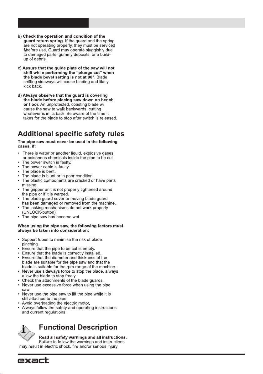
8. Safety instructions
Operation
10. Functional description
10. Product features
11. Before operating the tool
11. Connection to the mains power supply
11. Precise setting of the cutting point
11. Setting the pipe on supports
12. Attaching the pipe saw to the pipe
12. Piercing the pipe wall
12. Sawing around a pipe
13. Overload protection and rotation speed control
13. Improving possible misalignment of the cut
13. Model 280E cutting result adjustment
14. Model 410E cutting result adjustment
14. Installing and changing the saw blade
15. Maintenance and servicing instructions
15. Environment/Disposal
15. Guarantee/Guarantee conditions
16. Tips for using Exact PipeCut saws
Exploded view (separate attachment)
Definitions: Safety guidelines
The definitions below describe the level of severity for each signal word. Please read the manual and
pay attention to these symbols.
DANGER: Indicates an imminently hazardous situation which, if not avoided, will result in
death or serious injury.
WARNING: Indicates a potentially hazardous situation which, if not avoided, could result in
death or serious injury.
CAUTION: Indicates a potentially hazardous situation which, if not avoided, may result in
minor or moderate injury.
NOTICE: Indicates a practice not related to personal injury which, if not avoided, may result
in property damage.
Denotes risk of electric shock.
6
Information English
Operating, safety, and servicing instructions
Please read this operating, safety, and servicing instructions carefully before using
the pipe saw. Also store this instruction book somewhere accessible to everyone
using the pipe saw. In addition to these instructions, always follow the official work,
health and safety regulations. The Exact PipeCut is meant for professional use only.
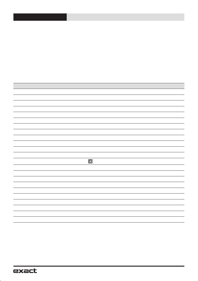
Technical data
Model Pipecut 280/PipeCut 410E
Voltage 1 230 V - 240 V / 50 Hz
Power 1750 W
No-Load speed I (low) = 2900/min, II (high) = 3900/min
Intermittent operation 2.5 min ON / 7.5 min OFF (S3 25% 10 min)
Blade diameter 165 mm (6.50”)
Mounting bore 62 mm (2.44”)
Weight 280E 9.0 kg (20 lbs)
Weight 410E 12.1 kg (26 lbs)
Range of use Ø 280E 40 mm – 280 mm (1.6”- 11”)
Range of use Ø 410E 75 mm – 410 mm (3.0”- 16”)
Max. pipe wall steel 10 mm (0.4”)
Max. pipe wall plastics 38 mm (1.5”)
Protection class
/ II
Spindle lock Yes
Speed preselection Yes
Constant electronic control Yes
Overload Protection Yes
Reduced starting current Yes
Vibration 2.84 m/s2
LpA (sound pressure) 90.6 dB(A)
KpA (sound pressure uncertanity) 3 dB(A)
LWA (acoustic power) 103.6 dB(A)
KWA (acoustic power uncertanity) 3 dB(A)
The values given are valid for nominal voltages [U] of 230/240 V. For lower voltage and models for
specific countries, these values can vary.
Please observe the article number on the type plate of your machine. The trade names of the
individual machines may vary. Only for power tools without reduced starting current: Starting cycles
generate brief voltage drops. Interference with other equipment/machines may occur in case of
unfavourable mains system conditions. Malfunctions are not to be expected for system impedances
below 0.36 ohm.

7
Information English
Noise/Vibration Information
Measured values determined according to EN60745.
Wear hearing protection!
Vibration total values (triax vector sum) determined according to EN60745:
Vibration emission value ah=2.84 m/s2, Uncertainty K =1.5 m/s2.
The vibration emission level given in this information sheet has been measured in accordance with
a standardised test given in EN 60745 and may be used to compare one tool with another. It may be
used for a preliminary assessment of exposure.
WARNING: The declared vibration emission level represents the main applications of the tool.
However if the tool is used for different applications, with different accessories or poorly
maintained, the vibration emission may differ. This may significantly increase the exposure level over
the total working period.
An estimation of the level of exposure to vibration should also take into account the times when the
tool is switched off or when it is running but not actually doing the job. This may significantly reduce
the exposure level over the total working period.
Identify additional safety measures to protect the operator from the effects of vibration such as:
maintain the tool and the accessories, keep the hands warm, organize work patterns.
Exact PipeCut 280E/410E pipecutting system,
Package contents:
Please check the package contains the following items:
1. Pipecutting System case
2. Exact PipeCut 280E or 410E pipe saw
3. Cutting supports × 4
4. Operating instructions
5. Hex socket key 5 mm (and 2 mm in 280E) fitted to the machine
6. TCT blade 165 × 62 fitted on the machine
7. DVD-video disc with instructions
OR
1.
2.
3. 4.
5.
6.
7.

8
Safety English
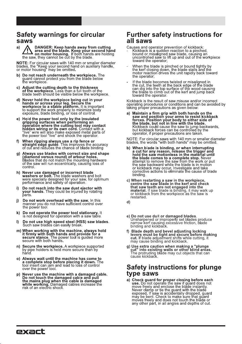
9
Safety English
Support large panels (pipes) to minimise the
risk of blade pinching and kickback. Large
panels (pipes) tend to sag under their own weight.
10
Safety English
Intended Use
PipeCut 280E / 410E:
The PipeCut 280E/410E pipe saw is intended
for use as a pipe fitter’s tool at the installation
site. The PipeCut 280E/410E pipe saw can only
be used to cut round pipes, with a diameter
of 280E: 40 mm – 280 mm (1.6”-11”) or 410E:
75 mm – 410 mm (3”-16”) and a maximum wall
thickness of 10 mm (0.4”) with steel and 38 mm
(1.5”) with plastics. The PipeCut 280E/410E pipe
saw can be used to cut all normal pipe materials,
such as steel, stainless steel, cast iron, copper,
aluminium and plastic. PipeCut 280E/410E
pipe saw is intended for short, intermittent use.
The machine may be loaded for 2.5 minutes
during a 10-minute period (S3 25 %). PipeCut
280E/410E pipe saw is not intended for use
in industrial production. Use pipe holders to
support pipe.
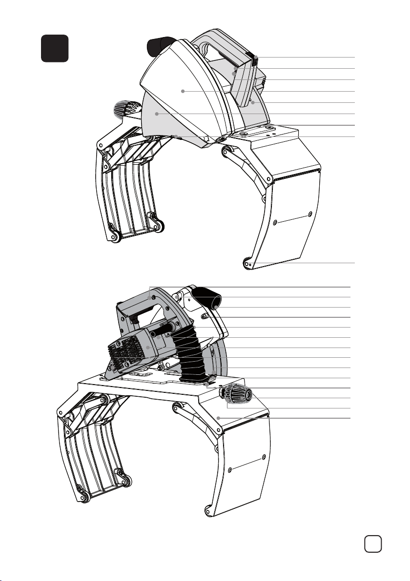
Product Features
While reading the operating instructions, unfold
the graphics page for the machine and leave it
open. This page is folded under the cover of this
manual (page 3). The following numbering of the
product features refers to this illustration.
Figure A
1. UNLOCK button
2. Power switch
3. Power-switch locking lever
4. Blade-guard cover
5. Overload indicator light
6. Moving blade-guard
7. Locking screws of adjustment
(in model 410E)
8. Edge of moving blade-guard
9. Adjustment wheel (in model 280E)
10. Operating handle
11. Chip removal lever
12. Chip removal nozzle
13. Blade-guard screw
14. Spindle-lock button
15. Rating plate
16. Motor unit
17. Speed control
18. Adjusting screw
19. Locking screw of adjustment
20. Pointer of adjustment
21. Gripper adjustment handle
22. Gripper safety
23. Gripper unit
11
Operation English
Exact PipeCut 280E/410E
pipecutting system
operating instructions
Before operating the tool
-Ensure that the motor unit is in the upright
position. The yellow mark of the UNLOCK
button is visible.
- Check that the blade is correctly fitted, in
good condition and suitable for the material
to be cut.
- Ensure the pipe saw guide wheels rotate.
- Ensure the support wheels rotate.
- Check the operation of the lower blade
guard.
- Ensure the pipe is empty.
- Check the position of chip removal lever.
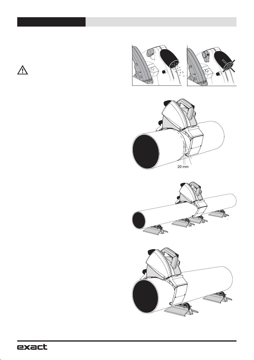
The pipe saw is equipped with a nozzle for
removing chips. When sawing plastic pipes, turn
the chip removal lever (Fig A/11) to “open” position
(Fig B), which opens the hatch in the blade
housing. If you attach a vacuum cleaner to the
chip removal nozzle, most of the plastic chips will
then fly out of the chip removal nozzle (Fig A/12)
and won’t remain inside the blade housing. When
sawing metal pipes, turn the lever to “close”
position (Fig B). The metal chips will drop out from
the bottom of the blade housing. Never attach
a vacuum cleaner when cutting metal pipes!
Connection to the mains power supply
Ensure that the mains voltage is the same as
indicated on the rating plate (Fig A/15). Connect
the pipe saw to the power outlet only after
having checked this.
Precise setting of the cutting point
When you mark the cutting point on the pipe to be
cut, deduct 20 mm from the required dimension
(Easy-to-remember rule: The cutting mark location
requires a measurement of - 20 mm.) (Fig C)
Setting the pipe on supports
Use the system supports when cutting pipes.
This will ensure safe working and optimum
result. Work on flat surface. Place the pipe on
two supports so that the cutting point is between
the supports. Place two more support under both
ends of the pipe. Check that all support wheel
contact the pipe (adjust if required e.g. with
pieces of lumber) (Fig D). When cutting short
and light weight pipes, place the supports so
that the cutting point is outside supports (Fig E).
Support the pipe with your left leg, if required.
Proper arrangements will prevent the blade from
jamming as the pipe is cut through.
Fig B
open closed
Fig C
Cutting point
Cutting mark
Fig D
Fig E
12
Operation English
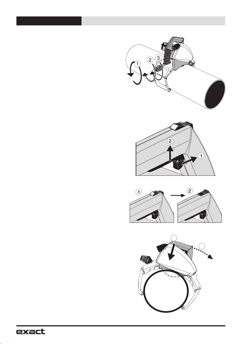
Attaching the pipe saw to the pipe
Open the pipe saw’s gripper unit enough to
suit the diameter of the pipe by rotating the
adjustment handle located at the rear of the saw
(Fig F/1).
Position the pipe saw on top of the pipe so
that the edge of the lower blade guard is at
the cutting mark. Fasten the pipe saw to the
pipe by turning the gripper adjustment handle
until the gripper grips firmly the pipe to be cut
(Fig F/2). Lock the mechanism by turning the
gripper safety (Fig F/3). Hold the pipe in place
and ensure that pipe saw moves freely in the
direction the pipe is fed. For sake of safety
ensure the pipe saw leads are to the left of the
pipe saw. The pipe saw is now ready for cutting.
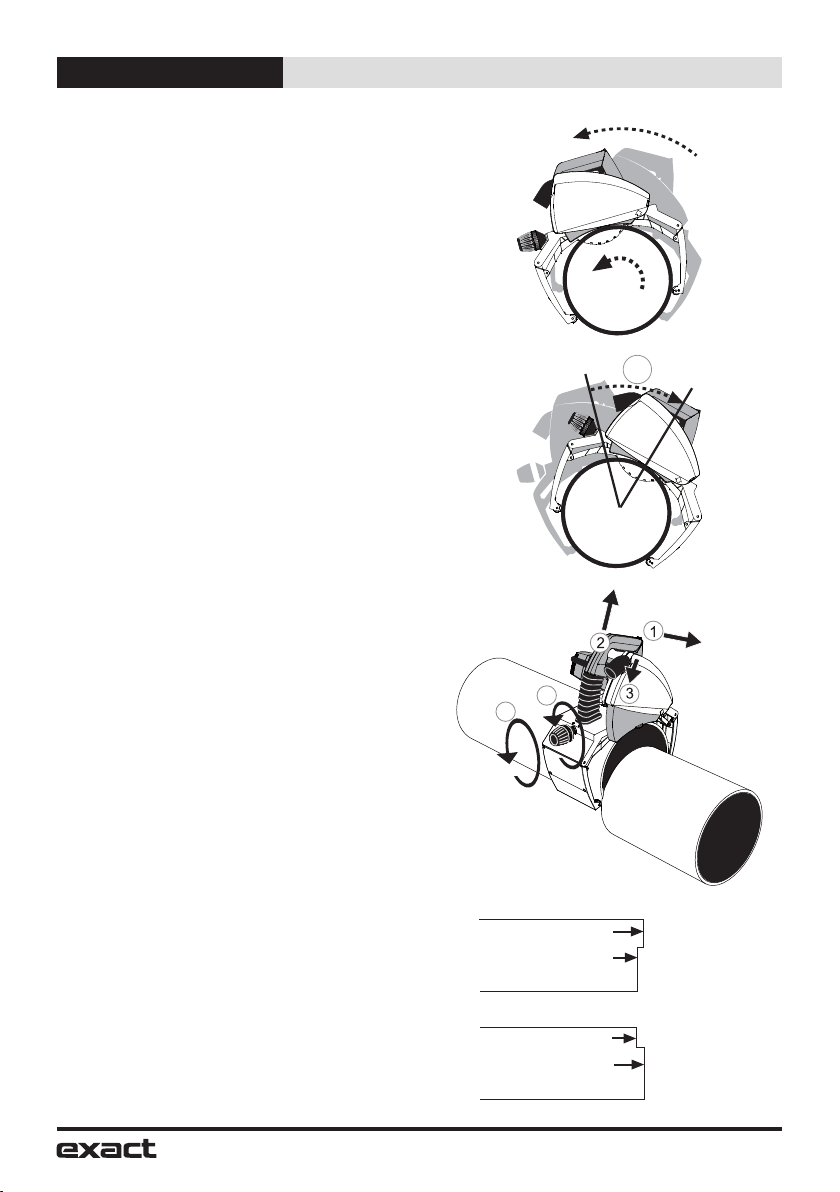
Piercing the pipe wall
Grip the gripper firmly with your right hand
and place your left foot on top of the pipe
approximately 50 cm from the pipe saw. Turn
the saw until it leans slightly forward (Figure I).
When starting the motor, first of all release the
power-switch locking lever (Fig G/1) and push
the power switch all the way down (Fig G/2).
Before starting to saw, wait until the blade
reaches full speed. Pierce the pipe wall by
pressing pipe saw operating handle downwards
slowly and evenly until the blade has cut through
the pipe wall (at this stage the pipe must not
rotate) and the motor unit is locked in the sawing
position (Fig I /1). Look at the UNLOCK button
during the piercing operation. When UNLOCK
button is locked, i.e. the yellow mark disappears
(Fig H), pipe saw is locked in the sawing
position, and you can safely start sawing around
the pipe.
Sawing around the pipe
Start sawing by feeding the pipe saw forward
and fix the pipe with your left foot (Fig I /2). After
that release the pipe (remove your left foot from
the pipe) and turn the pipe saw backwards,
whereby the pipe will also be rotated backwards
(Fig J). Start a new feeding movement, and
feed continuously forward ca. 1/6 of the
pipe’s circumference. Repeat until the pipe is cut
off (Fig K).
Select the sawing / feeding speed as per the
material and the thickness of the wall. Too high
speed can damage the blade, overload the pipe
saw and give a poor sawing result.
Fig F
Fig G
Fig H
Fig I
2
1
13
Operation English
When the pipe is cut off, push the UNLOCK
button forward until the yellow mark is visible
and the locking is released (Fig L/1). Now raise
the motor unit to starting position (Fig L/2).
Release the power switch (Fig L/3). When the
blade has stopped, open the gripper safety
mechanism (Fig L/4) and disengage the pipe
saw from the pipe by loosening the gripper
adjustment handle (Fig L/5). Ensure that the
moving lower blade-guard is lowered into safety
position
Should there be problems during piercing or
sawing, abnormal sounds or vibrations due to
which you have to interrupt sawing before the
pipe is cut through, release the blade by pushing
the UNLOCK button forward until the UNLOCK
button is released, and lift the motor unit up.
Once the problem is cleared, start sawing again.
Never start the motor, when the motor unit is
locked in sawing position or teeth of the blade
contact the pipe to be sawn.
Overload protector and rotation speed
control
The saw has a two-speed rotation speed control
(Fig A/17). When sawing stainless or acid-proof
steel use the lower rotation speed l. When
sawing other materials use the faster rotation
speed ll. The saw also has an overload protector
which switches the power off automatically in
an overload situation. The motor part has a red
indicator light (Fig A/5), which flashes alerting
you to the overload and is lit continually when the
overload protector has been triggered. If the light
begins to flash, the motor must be cooled down.
Stop sawing and allow the motor to cool down.
You can speed up the cooling process by running
the motor without loading it. When the motor has
cooled down sufficiently, the light will stop flashing
or turns off and you can continue sawing.
Improving possible misalignment of the cut
The cut is affected by many factors, e.g. the
size of the pipe, the material, the wall thickness,
the quality of the pipe’s surface, the roundness,
welded seams, blade condition, feed rate,
operator’s experience. For this reason the saw
may move to left or right cusing unperfect cut
(see Fig M). Cutting result can be improved as
following with models 280E and 410E.
Model 280E cutting result adjustment
The model 280E gripper unit has 8 guidance
wheels. One of those is called adjustment wheel
(Fig A/9). Note that the adjustment of this wheel
applies only to the actual pipe size and material,
and the wheel may have to be readjusted as the
blade is worn.
Fig J
Fig K
1/8
Fig L
4
5
Fig M
a
b
start of the cut
end of the cut
start of the cut
end of the cut
Saw has moved from right to left
Saw has moved from left to right
14
Operation English
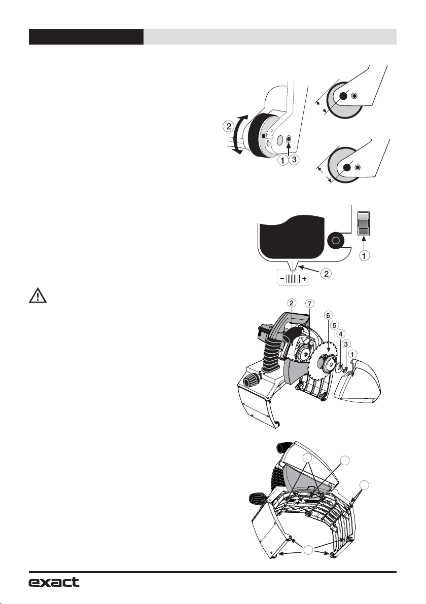
To adjust the wheel, loosen the locking screw
(Fig N/1) and turn the wheel centre clockwise or
counter clockwise to the desired position (Fig N/2),
and lock the wheel again (Fig N/3). If the saw
has moved from right to left (Fig M/a) rotate the
center part of the adjusting wheel so that the “d” is
smaller (Fig N/a). If the case is like in Fig M/b do
like shown in Fig N/b. Remember to lubricate the
adjusting wheel at regular intervals.
Model 410E cutting result adjustment
In model 410E the angle of whole motor unit is
changed to improve the cutting result: Loosen
3 locking screws of adjustment (Fig A/7 + A/19).
If the saw has moved from right to left (Fig M/a)
rotate the adjusting screw (Fig A/18, O/1) so that
the pointer (Fig A/20, O/2) moves to the left (-).
If the case is like in Fig M/b. rotate respectively
to the right (+). After adjusting tighten the
3 locking screws of adjustment. Note! There is
some backlash in the adjusting screw before the
pointer starts to move.
Installing and changing
the saw blade
WARNING: To reduce the risk of injury,
turn unit off and disconnect it from
power source before installing and
removing accessories, before adjusting or
when making repairs. An accidental start-up
can cause injury.
Remove the power plug from the socket. Check
that the motor unit is locked in the upper position.
Remove the blade guard cover (Fig P/1) by
opening the screw (Fig P/2). Press the spindle-
lock button (Fig A/14) and simultaneously rotate
the blade by hand until the spindle-lock button
drops a further distance of about 7 mm. Now the
rotation of the blade is prevented. Use the blade
key to open the blade attachment bolt. Remove
the securing bolt (Fig P/3), the washer (Fig P/4),
the blade flange disc (Fig P/5), and the blade
(Fig P/6).
Before installing a new blade, check that both
blade flange discs are clean. Place a new or
sharpened blade on the back flange disc (Fig P/7),
so that the marked side of the blade is facing
outwards and the arrows on the blade are facing
in the same direction as the rotation direction
markings on the inside of the blade case. Ensure
that the new blade goes right to the bottom in
the back flange disc. Put the blade flange disc,
the washer, and the securing bolt back in place.
Press the spindle lock button and tighten the blade
securing bolt. Put the blade guard cover back in
place and tighten the finger bolts.
Fig N
d
a
d
b
Rotate wheel so that dis smaller
Rotate wheel so that dis bigger
Fig O
Fig P
Fig Q
1
2
3
4
15
Maintenance, Environment, Guarantee English
Maintenance and
servicing instructions
Remove the power plug from the socket
before servicing or cleaning the pipe saw. All
maintenance operations carried out on the pipe
saw’s electrical components must be carried out
at an approved service agency.
Blade
Check the condition of the blade. Replace
a bent, blunt, or otherwise damaged blade with
a new one. Using a blunt blade can overload the
pipe saw’s electric motor. When you notice that
the blade is blunt, do not continue sawing with
it, as the blade may become so badly damaged
that it will not be worth sharpening. A blade in
sufficiently good condition can be sharpened
a few times by a professional sharpening
company.
Gripper unit
Clean the gripper unit regularly with compressed
air. Lubricate the gripper’s wheel axles (Fig Q/1)
and its joints (Fig Q/2). Also clean and lubricate
the gripper’s trapezoidal screw (Fig Q/3) and the
two worm screws on it (Fig Q/4).
Blade guard
When you have sawn plastic pipes and then
intend to start sawing metal pipes always clean
the inside of the blade guards. Hot particles
derived from sawing metal will burn plastic
particles, which may release toxic smoke. Make
it a rule to clean the blade guard regularly, and
pay special attention to keep the moving blade
guard movement from becoming hampered.
Lubricate the axis of the moving blade guard
regularly.
Motor
Keep the motors cooling vents clean.
Plastic parts
Clean the plastic parts with a soft rag. Only use
mild detergents. Do not use solvents or other
strong detergents as they may damage the
plastic parts and paint surfaces.
Power cable
Check the condition of the power cable regularly.
A faulty power cable should always be replaced
at an approved service agency.
Correct use and regular servicing and cleaning
will ensure the continued operation of the pipe
saw.
Environment
Separate collection. This product
must not be disposed of with normal
household waste. When your Exact
PipeCut machine is worn out, do not
dispose of it with normal household
waste. This product must be recycled
separately. Separate recycling of used
products and packaging facilitate
recycling and recovery of materials. Reusing
of recycled materials helps prevent pollution of
environment. According to local regulations it
is possible to deliver household appliances to
municipal rubbish depositories or to the dealer
when buying a new product.
Guarantee
Warranty terms valid from 01.01.2015
If the Exact PipeCut Saw becomes unusable
due to material or manufacturing defects within
the Warranty Term or *Extended Warranty
Term at our discretion we will repair the Exact
PipeCut Saw or supply an entirely new or factory
reconditioned Exact PipeCut Saw at no charge.
Warranty Term / *Extended Warranty Term
The Exact Tools Warranty Term is for 12 months
from date of purchase. *By registering on-line
(exacttools.com/Warranty Registration) you
will receive an additional 12 months Warranty
Term for FREE. Warranty registration must be
completed within one month of purchase.
Password for registration is: 1yearmore
The Warranty is only valid if:
1.) Copy of a dated purchase receipt is returned
to the Authorized Warranty Repair Center or
has been uploaded to our website at the time
of warranty registration.
2.) The Exact PipeCut Saw has not been
misused.
3.) No attempt has been made by non-approved
persons to repair the saw.
4.) The Exact PipeCut Saw has been used in
accordance with the operating, safety, and
servicing instructions provide in the manual.
5.) The Exact PipeCut Saw has been delivered
to an Authorized Warranty Repair Center
within the term of the warranty.

16
Tips English
Note: The Exact PipeCut Saw is to be shipped
to the Authorized Warranty Repair Center freight
prepaid. If the Exact PipeCut Saw is repaired
under Warranty the return shipment will be made
freight prepaid. If the Exact PipeCut Saw is not
repaired under Warranty the return shipment will
be made freight collect.
Please Note: The following items or services
are excluded from Warranty claims:
- Saw Blades
- Overload Protection Fuse
- Carbon Brushes
- Gripping Unit Wheels
- Blade Flange
- Attachment Flange
- Pulling Flange Washer
- Normal Wear and Tear
- Errors Due to Misuse or Accident
- Water, Fire and Physical Damage
- Power Cords
- Adjustment of Adjustment Wheel
- If a wrong type of generator has been used
as power source
Tips for using Exact
PipeCut saws
Diamond blade should only be used for cutting
cast iron pipe. It is not recommended to cut cast
iron with TCT or Cermet blades.
Clean the inside of the blade guards after cutting
plastic pipe.
Smaller pipe is easily cut by rotating the pipe
by hand either on a table or on the floor. Please
note: rotate pipe towards you when rotating by
hand and be careful not to rotate too fast.
Check the condition of the blade regularly.
The cutting procedure is divided into two stages;
first saw through the pipe wall, then complete
the cut by sawing around it.
Do not overload the saw by cutting continuously.
The saw will be overheated and the metal parts
can become burning hot. This will also damage
the motor and the blade. The rule is 2.5 minutes
in use and 7.5 minutes rest.
Keep the feeding speed constant. This will
extend the lifetime of the blade. For example
cutting time for a steel pipe diameter of 6’’
(170 mm), and a wall thickness of 1/5’’ (5 mm),
is 15-20 seconds, and for a cast-iron pipe
diameter of 4’’ (110 mm), with a wall thickness of
1/6’’ (4 mm) is 20 to 25 seconds.
Always keep the motor unit in the upright
position. The yellow mark of the unlock button is
then visible. Never place the Pipe Cut Saw on
the pipe in the locked / cutting position.
Factors that affect the lifetime of the saw
blade:
• material of the pipe
• correct blade type for material being cut
• correct motor speed setting
• wall thickness of the pipe
• feeding speed
• smoothness of the pipe
• user’s general skills
• cleanness of the pipe
• rust on the pipe
• welded seam in the pipe
• blade speed
Factors that affect the straightness of the
cut:
• condition of the saw blade
• wall thickness of the pipe
• feeding speed
• smoothness of the feed
• user’s general skills
• cleanness of the pipe
• roundness of the pipe
• gripper unit too loose or too tight
• blade assembled too tight
Due to continuous product development,
the information in this instruction book may
change. We do not give separate notification
of changes.
Please see more information at our web-site
www.exacttools.com
This manual suits for next models
1
Table of contents
Other eXact Cutter manuals

eXact
eXact PipeCut+Bevel 170E User manual

eXact
eXact PipeCut P400 User manual

eXact
eXact PipeCut 170 User manual

eXact
eXact PipeCut 170 User manual

eXact
eXact PipeCut 170 User manual

eXact
eXact PipeCut 220 INOX Series User manual

eXact
eXact PipeCut 360 system User manual

eXact
eXact PipeCut 280E System User manual

eXact
eXact Pipecut 280 Pro Series User manual

eXact
eXact PipeCut V1000 User manual


