Cembre B35M-TFC User manual

1
ENGLISH
FRANÇAIS
DEUTSCH
ESPAÑOL
ITALIANO
BATTERY OPERATED HYDRAULIC CUTTING TOOL
COUPE-CABLE HYDRAULIQUE SUR BATTERIE
HYDRAULISCHES AKKU-SCHNEIDWERKZEUG
HERRAMIENTA HIDRÁULICA DE CORTE A BATERíA
UTENSILE OLEODINAMICO DA TAGLIO A BATTERIA
14 M 170
OPERATION AND MAINTENANCE MANUAL
NOTICE D'UTILISATION ET ENTRETIEN
BEDIENUNGSANLEITUNG
MANUAL DE USO Y MANTENIMIENTO
MANUALE D'USO E MANUTENZIONE
B35M-TFC
B35M-TFCA
B35M-TFCE
B35M-TFCT
ENGLIS
H
14 M 17
0

2
– Before using the tool, carefully read the instructions in this manual.
– Avant d'utiliser cet outil, lire attentivement les instructions de cette notice.
– Vor Inbetriebnahme unbedingt die Bedienungsanleitung durchlesen.
– Antes de utilizar la herramienta, leer atentamente las instrucciones contenidas en este manual.
– Prima di utilizzare l'utensile, leggere attentamente le istruzioni contenute in questo manuale.
– Keep hands clear of cutting blade.
– Au cours du coupage, tenir les mains éloignées de la lame.
– Während des Schneidvorganges die Hände vom Messer fernhalten.
– Durante el corte, tener las manos alejadas de la cuchilla.
– Durante il taglio, tenere le mani lontane dalla lama.
– See page 34.
– Voir page 34.
– siehe Seite 34.
– Vease página 34.
– Vedere pagina 34.
WARNING LABELS - ETIQUETTES SIGNALETIQUES - WARNSCHILDER -
ETIQUETAS DE ATENCION - ETICHETTE D'AVVERTENZA
– Never throw batteries into fire or water.
– Jamais jeter les batteries dans le feu ou dans l'eau.
– Werfen Sie Akkus nicht in das Feuer oder Wasser.
– Nunca tire las baterías al fuego o al agua.
– Mai gettare le batterie nel fuoco o in acqua.
– Always recycle the batteries.
– Recycler toujours les batteries.
– Verbrauchte Akkus stets dem Recycling zuführen.
– Reutilizar siempre las baterías.
– Riciclare sempre le batterie.
– Do not discard batteries into domestic refuse or waste disposal.
– Ne pas jeter de batteries dans une poubelle ou autre lieu non prévu à cet effet.
– Verbrauchte Akkus nicht der allgemeinen Abfallentsorgung zuführen.
– No tirar las baterías al cubo de basura o lugar paracido.
– Non buttare le batterie fuori uso nei cestini della spazzatura o luoghi simili.
Tool - Outil - Werkzeug - Herramienta - Utensile
Battery - Batterie - Akku - Batería - Batteria

3
4
OPERATING BUTTON
BOUTON D'ACTIONNEMENT
STARTKNOPF
PULSADOR DE ACCIONAMIENTO
PULSANTE DI AZIONAMENTO
RESIDUAL BATTERY ENERGY DISPLAY
INDICATEUR DE CHARGE DE BATTERIE
AKKUANZEIGE
INDICADOR DE CARGA DE LA BATERIA
INDICATORE DI CARICA DELLA BATTERIA
9
PRESSURE RELEASE BUTTON
BOUTON DE DECOMPRESSION
DRUCKABLASSKNOPF
PULSADOR DE DESBLOQUEO PRESION
PULSANTE SBLOCCO PRESSIONE
3
BATTERY
BATTERIE
AKKU
BATERIA
BATTERIA
21
HEAD SUPPORT
SUPPORT TETE
KOPFHALTER
SOPORTE CABEZA
SUPPORTO TESTA
13
BLADE
LAME
MESSER
CUCHILLA
LAMA
15
BATTERY RELEASE
DEBLOCAGE BATTERIE
AKKU ENTRIEGELUNG
DESBLOQUEO BATÉRIA
SBLOCCO BATTERIA
18
LOCKING HANDLE
POIGNEE DE BLOCAGE
SPERRHEBEL
PALANCA DE SUJECION
LEVA DI BLOCCAGGIO
2

4
ENGLISH
The part reference includes the following:
– Basic tool complete with battery.
– Spare battery.
– Battery charger (model depends on the tool version).
– Plastic carrying case.
BATTERY OPERATED HYDRAULIC CUTTING TOOL
1. GENERAL CHARACTERISTICS
TOOL TYPE:
B35M-TFC
Acoustic Noise (Directive 2006/42/EC, annexe 1, point 1.7.4.2 letter u)
– The weighted continuous acoustic pressure level equivalent
A at the work place LpA is equal to .............................................................................................................. 64,9 dB (A)
– The maximum value of the weighted acoustic displacement
pressure C at the work place LpCPeak is equal to ........................................................................................ 99,7 dB (C)
– The acoustic power level emitted by the machine
LWA is equal to .................................................................................................................................................... 69,3 dB (A)
Risks due to vibration (Directive 2006/42/EC, annexe 1, point 2.2.1.1)
Tests carried out in compliance with the indications contained in EN ISO 5349-1/2 Standard, and under
operating conditions much more severe than those normally found, certify that the weighted root mean
square in frequency of the acceleration the upper limbs are exposed to for each biodynamic reference
axis is 0,527 m/sec2 max.
Application range:
Rated operating pressure bar (psi):
Dimensions
LxWxH
mm (inches):
Weight with battery kg (lbs):
Motor Volt DC:
Battery
type
CB1820L Volt / Ah:
Recommended oil:
Safety:
Operating temperature °C (°F):
Battery charger ASC30-36
Input Volt / Hz:
W:
suitable for cutting grooved contact wires and
conductors used on electric traction systems.
450 (6,500)
385 x 195 x 133 (15.2 x 7.7 x 5.2)
3,4 (7.5)
18
18 / 2.0 Li-Ion
ENI ARNICA ISO 22 or
ESSO INVAROL EP22
or equivalent
the tool is equipped with a maximum pressure valve
-15 to +50 (+5 to +122)
B35M-TFCE B35M-TFCT B35M-TFCA
UE
27044000
UK
27045000
AUS/NZ
27047000
USA/CAN
27046000
220 - 240 / 50 - 60
85
115 / 60

5
ENGLISH
2. INSTRUCTIONS FOR USE
2.1) Setting
Select the appropriate die set. Two styles of die set are available:
–Die Sets for cutting contact wire: the die profile matches the profile of the contact wire.
–Die Sets for cutting conductor: the die profile matches the profile of the conductor.
2.2) Positioning (Ref. to Figs. 1, 2, 3 and 4)
– Insert the die set into the head (see § 2.6).
– Position the conductor inside the die set so that the blade (13) lines up with the desired cutting
point.
– Close the die set (see fig. 2) by moving the locking handle (18) towards the tool body, until au-
tomatically‘locked’ in position and securely clamping the wire/conductor (see fig. 3).
– Press operating button (4) to activate the motor-pump group for the advancement of the blade
(13) to the conductor (see fig. 4).
Before proceeding with the cutting operation, ensure that the locking pin (17) is fully inserted
into the head and the locking handle (18) is securely locked in position.
Check that the cutting edge of the blade coincides with the desired cutting point, otherwise
re-open dies following instructions as per § 2.5 and reposition the wire / conductor.
2.3) Cutting
Continue pressing operating button (4): the blade (13) progressively advances until the conductor
is completely cut in a clean and precise manner, without deforming the conductor itself.To halt the
advancement, release operating button (4) and the motor will cut out.
The motor will continue to operate after the maximum pressure relief valve has activated.
No further cutting force is applied, the oil is bypassed and returned to the reservoir.
DONOT ATTEMPT TO CUT STEEL RODS WITH THIS TOOL.
2.4) Head rotation
For ease of operation, the tool head can rotate through 180°, allowing the operator to work in the
most comfortable position.
Warning: Do not attempt to turn the head if the hydraulic circuit is pressurised.
2.5) Release of dies
– Press the pressure release button (9) for rapid retraction of the ram (16).
– By releasing the locking handle (18) the dies open and release the wire/conductor.
2.6) Inserting the die set (Ref. to Figs. 1 and 5)
– Remove the locking pin (17) and insert the die set into the top of the tool and position the‘loca-
tor’ (A) in the guide at the bottom of the head. Ensure that the recess (B) on the front of the die
set faces the blade (13).

6
ENGLISH
– Fully insert the locking pin (17) into the head.
The die set is polarised and can only be installed one way to ensure the correct insertion of
the locking pin (17).
– To remove the die set from the head: open the locking lever (18), completely remove the locking
pin (17) and slide the die set out of the tool.
2.7) Battery status
The battery is equipped with LED indicators that indicate the remaining battery life at any time by
pressing the adjacent button (P).
4 LEDs illuminated: Fully charged
2 LEDs illuminated: 50 % capacity
1 LED flashing: Minimum charge, replace the battery
WHEN THE BATTERY VOLTAGE HAS DROPPED BELOW AMINI-
MUM SAFETY THRESHOLD, THE TOOL WILL NOT START, AND IT
IS NECESSARY TO RECHARGE OR REPLACE THE BATTERY.
The approximate time to fully recharge a battery is about 40 minutes.
2.8) Insertion/replacement of battery
To replace the battery, remove it by pressing the release button (15) (Ref. to Fig. 6 page 26), then
insert the new battery, sliding it into the guides until it locks.
3. WARNING
THE TOOL IS UNSUITABLE FOR CONTINUOUS USE AND SHOULD BE ALLOWED TO COOL DOWN
FOLLOWING UNINTERRUPTED,SUCCESSIVE CUTTING OPERATIONS;FOR INSTANCE,HAVING EXHAUSTED
AFULLY CHARGED BATTERY IN ONE SESSION, DELAY BATTERY REPLACEMENT FOR AFEW MINUTES.
OBSERVE RECOMMENDED REST PERIODS ALSO WHEN USING AN EXTERNAL POWER SUPPLY.
DONOT USE THIS TOOL ON LIVE CABLES.
PROTECT THE TOOL FROM RAIN AND MOISTURE. WATER WILL DAMAGE THE TOOL AND BATTERY.
ELECTRO-HYDRAULIC TOOLS SHOULD NOT BE OPERATED IN POURING RAIN OR UNDER WATER.
3.1) Using the battery charger
Carefully follow the instructions in the battery charger manual.
4. MAINTENANCE
The tool is robust, completely sealed, and requires very little daily maintenance.
Compliancewiththefollowingpointsshouldhelptomaintain theoptimum performanceofthetool:
2P
W
HEN THE BATTERY V
O
LTAGE HAS DR
O
PPED BEL
O
WAMINI-
MUM SAFETY THRESHOLD, THE TOOL WILL NOT START, AND IT
IS NECESSARY TO RECHARGE OR REPLACE THE BATTERY
.

7
ENGLISH
4.1) Thorough cleaning
Dust, sand and dirt are a danger for any hydraulic device.
Every day, after use, the tool must be wiped with a clean cloth taking care to remove any residue,
especially close to moveable parts.
4.2) Storage
When not in use, the tool should be stored and transported in the plastic case to prevent damage.
The case is suitable for storing the tool and accessories.
Plastic case: VAL P43, size 502x380x137 mm (19.8x15x5.4 inches) weighs 2,6 kg. (5.7 lbs).
4.3) Blade replacement
After extended use, the blades may loose their
cutting edge.
Replace the blades as follows:
– Remove the die set from the tool, operate
the tool to advance the blade (13) until the
split pin (5) in the ram (16) is accessible.
– Use a suitable drift to remove the split pin
(5) and release the blade (13).
– Note the orientation of the blade (13).
Remove the blade and fit the replacement.
Fit the split pin (5) and release the oil pressure.
5. RETURN TO Cembre FOR OVERHAUL
In the case of a breakdown contact our Area Agent who will advise you on the problem and give
you the necessary instructions on how to dispatch the tool to our nearest service Centre; if possible,
attach a copy of theTest Certificate supplied by Cembretogether with the tool or fill in and attach
the form available in the“ASSISTANCE” section of the Cembre website.
5
16
13

8
FRANÇAIS
OUTIL HYDRAULIQUE DE SERTISSAGE SUR BATTERIE
1. CARACTERISTIQUES GENERALES
L'ensemble comprend:
– Outil de base avec batterie.
– Batterie de rechange.
– Chargeur de batterie (différent en fonction de la version de l'outil).
– Coffret de rangement.
OUTIL TYPE:
B35M-TFC
Pression sonore aérienne (Directive 2006/42/CE, annexe 1, point 1.7.4.2, lettre u)
– Le niveau de pression sonore continue équivalente
pondérée A sur le poste de travail LpA est .................................................................................................. 64,9 dB (A)
– Le niveau de pression sonore instantanée pondéré
C sur le poste de travail LpCPeak est.................................................................................................................. 99,7 dB (C)
– Le niveau de puissance acoustique dégagée par la
machine LWA est.................................................................................................................................................... 69,3 dB (A)
Risques dérivés des vibrations (Directive 2006/42/CE, annexe 1, point 2.2.1.1)
Des relevés réalisés suivant les indications de la Norme EN ISO 5349-1/2, dans des conditions de service
largement représentatives des conditions d’emploi normales témoignent que la valeur quadratique
moyenne pondérée en fréquence de l’accélération à laquelle sont exposés les membres supérieurs pour
chaque axe biodynamique de référence est de 0,527 m/sec2maxi.
Domaine d'application:
Pression nominale bar (psi):
Dimensions
LxLxH
mm (inches):
Poids avec batterie kg (lbs):
Moteur Volt DC:
Batterie
type
CB1820L Volt / Ah:
Huile recommandée:
Sécurité:
Température de fonctionnement °C (°F):
Chargeur de batterie ASC30-36
Alimentation Volt / Hz:
W:
conçu pour la coupe des fils rainurés des lignes
aériennes de contact et conducteurs en général.
450 (6,500)
385 x 195 x 133 (15.2 x 7.7 x 5.2)
3,4 (7.5)
18
18 / 2.0 Li-Ion
ENI ARNICA ISO 22 ou
ESSO INVAROL EP22
ou équivalents
l’outil est équipé d'une valve de surpression
-15 à +50 (+5 à +122)
B35M-TFCE B35M-TFCT B35M-TFCA
UE
27044000
UK
27045000
AUS/NZ
27047000
USA/CAN
27046000
220 - 240 / 50 - 60
85
115 / 60

9
FRANÇAIS
2. INSTRUCTIONS D'UTILISATION
2.1) Mise en service
Choisir le type de bloc-matrices adapté au conducteur (fil de contact ou conducteur) à couper; deux
types de bloc-matrices sont prévus:
– Pour la coupe des fils rainurés de contact: le bloc-matrices a une forme qui reproduit le profil
du fil de contact à couper.
– Pour la coupe de conducteurs: le bloc-matrices est de dimensions adaptée au conducteur à
couper.
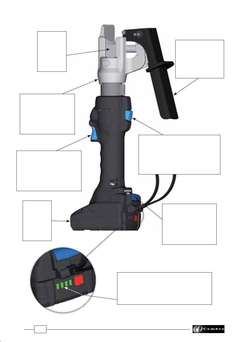
2.2) Positionnement (Voir Fig. 1, 2, 3 et 4)
– Introduire le bloc-matrices à l'intérieur de l'outil (voir § 2.6).
– Placer le conducteur à l'intérieur du bloc-matrices de façon à ce que la lame (13) se trouve au
niveau du point de coupe souhaité.
– Fermer les matrices (voir fig. 2) en portant la poignée de blocage (18) vers le bas jusqu'à son
verrouillage; le conducteur est alors positionné pour la coupe (voir fig. 3).
– Appuyer sur la gâchette de commande (4) pour mettre en marche le groupe moteur-pompe;
la lame commence à s’approcher du conducteur (voir fig. 4).
Avant de procéder à l'opération de coupe, veiller à ce que l'axe (17) soit engagé à fond et que la
poignée de blocage (18) soit parfaitement verrouillée.
S'assurer que la lame se trouve au niveau du point de coupe souhaité; sinon desserrer les matrices
en suivant les instructions du § 2.5 et repositionner le conducteur.
2.3) Coupe
En maintenant la gâchette (4) pressée, on continue à faire tourner le moteur; la lame (13) avancera
progressivement jusqu'à la coupe complète du conducteur qui sera effectuée de façon nette et
précise sans aucune déformation de celui-ci.
Si on maintient la gâchette (4) pressée après avoir fini de couper le câble, on entendra rapidement
se déclencher la valve de surpression; cette dernière dévie directement l’huile dans le réservoir et
non plus vers le piston, annulant ainsi toute pression sur la lame.
NEPAS COUPER DE ROND MASSIF EN ACIER.
2.4) Rotation de la tête
La tête de l'outil pivote de 180° par rapport au corps,permettant à l'utilisateur de travailler dans la
meilleure position.
Attention: ne pas forcer la rotation de la tête, lorsque le circuit hydraulique est sous pression.
2.5) Réouverture des lames
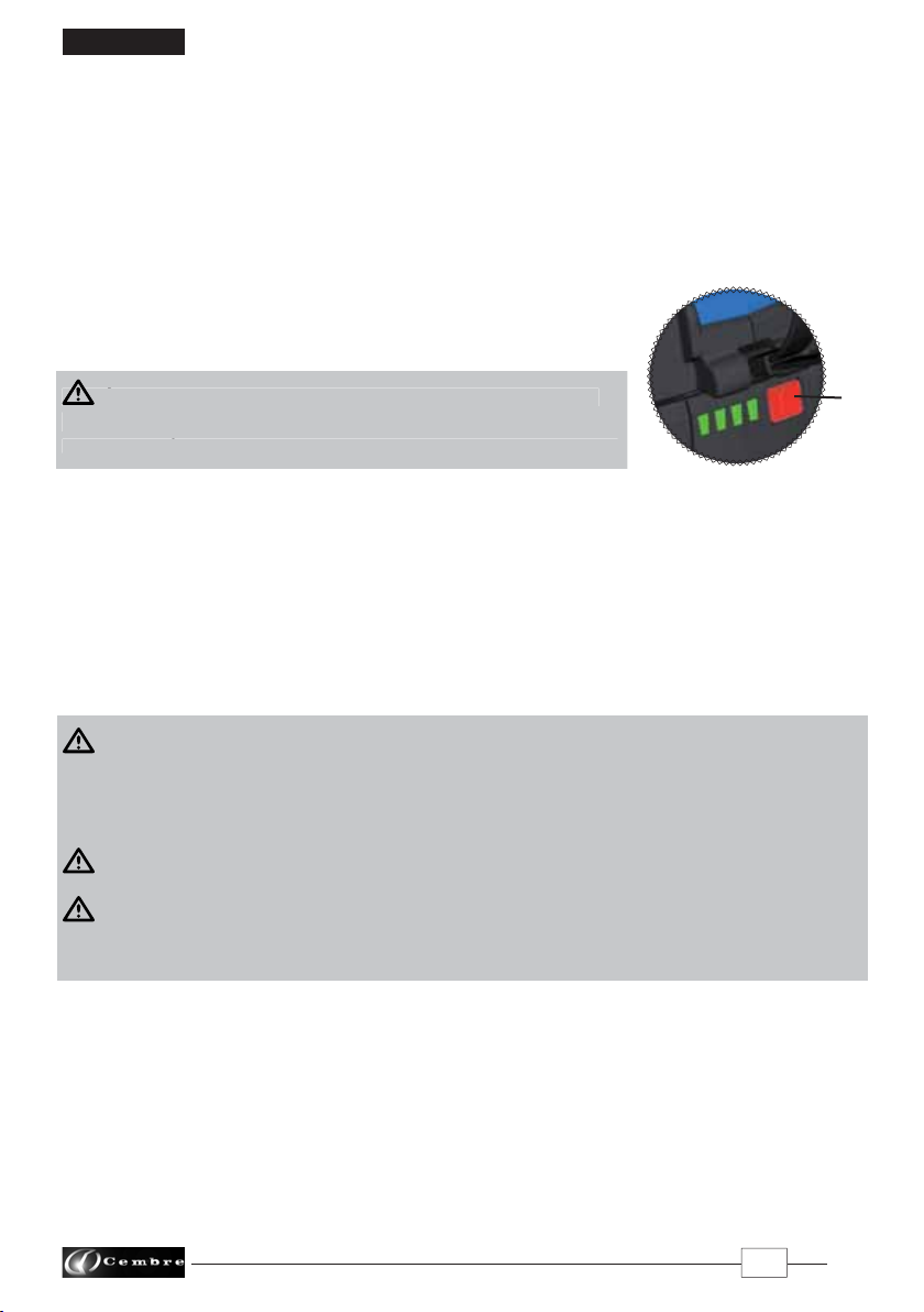
– Appuyer à fond sur le bouton de décompression (9), on provoque le retour du piston et par
conséquent l'ouverture des lames.
– Débloquer la poignée (18); les matrices s'ouvrent et le conducteur est libéré.
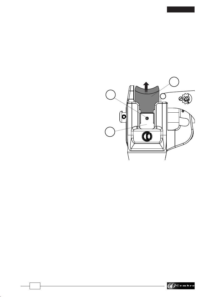
2.6 Introduction du bloc-matrices (Voir Fig. 1 et 5)
– Extraire l'axe (17) et introduire le bloc-matrices à l'intérieur de l'outil par le haut de façon à ce que
les guides (A) se placent dans la gorge du fond de la tête et que les dégagements (B) sur le devant
des matrices soient tournés vers la lame (13).

10
FRANÇAIS
– Introduire l'axe (17) à fond jusqu'à la butée.
Le positionnement du bloc-matrices à l'intérieur de l'outil est "détrompé"; la mise en place de
l'axe (17) ne sera possible que s'il est introduit correctement.
– Pour enlever le bloc-matrices de la tête, débloquer la poignée (18), extraire complètement l'axe
(17) et sortir le bloc par le haut.
2.7) Autonomie de la batterie
La batterie est équipée d’indicateurs à LED qui permettent de contrôler, à tout moment, son auto-
nomie résiduelle en appuyant sur la touche (P).
4 led allumées: autonomie maximale
2 led allumées: autonomie à 50 %
1 led clignotante: autonomie minimale, remplacer la batterie.
LORSQUE LA TENSION DE LA BATTERIE DESCENDUE AU-DESSOUS
DU SEUIL MINIMAL DE SÉCURITÉ, L’OUTIL NE DÉMARRE PAS, IL EST
DONC NÉCESSAIRE DE RECHARGER OU DE REMPLACER LA BATTERIE.
À titre indicatif, le délai de recharge complète de la batterie correspond à environ 40 min.
2.8) Introduction/replacement de la batterie
Pour remplacer la batterie, la retirer en appuyant sur le mécanisme de déblocage (15) (Voir Fig. 6,
page 26), puis introduire la nouvelle batterie en la faisant coulisser sur les guides jusqu’au blocage
complet.
3. PRECAUTIONS
L’OUTIL N’EST PAS CONÇU POUR UNE UTILISATION EN CONTINU;APRÈS AVOIR EFFECTUÉ UNE QUANTITÉ
D'OPÉRATIONS DE COUPE CONSÉCUTIVES ÀPARTIR D’UNE BATTERIE COMPLÈTEMENT CHARGÉE, AU
MOMENT DU REMPLACEMENT DE LA BATTERIE,NOUS SUGGÉRONS D’OBSERVER UNE PÉRIODE D’ARRÊT
POUR PERMETTRE LE REFROIDISSEMENT DE L’OUTIL.
NEPAS UTILISER L'OUTIL SUR DES CONDUCTEURS SOUS TENSION.
PROTÉGER L’OUTIL DE LA PLUIE ET DE L’HUMIDITÉ. L’EAU POURRAIT ENDOMMAGER L’OUTIL ET LA
BATTERIE LES OUTILS HYDRO-ELECTRIQUES NE DEVRAIENT PAS ÊTRE UTILISÉS SOUS LA PLUIE ET SOUS
L’EAU.
3.1) Utilisation du chargeur de batterie
Suivre attentivement les instructions indiquées sur le manuel.
4. ENTRETIEN
Cet outil est robuste,complètement scellé et ne nécessite aucune préoccupation ou entretien par-
ticulier. Les recommandations qui suivent sont néanmoins souhaitables pour assurer une longévité
optimum:
2P
LORSQUE LA TENSION DE LA BATTERIE DESCENDUE AU-DESSOUS
DU SEUIL MINIMAL DE SÉCURITÉ
,
L’OUTIL NE DÉMARRE PAS
,
IL EST
DONC NÉCESSAIRE DE RECHARGER OU DE REMPLACER LA BATTERIE.

11
FRANÇAIS
4.1) Nettoyage élémentaire
Veiller à protéger l'outil de la poussière, du sable et de la boue qui sont un danger à tout système
hydraulique. Chaque jour après utilisation, l'outil doit être nettoyé à l'aide d'un chiffon propre, tout
particulièrement aux endroits de pièces mobiles.
4.2) Rangement
Au repos, pour protéger l'outil des coups accidentels et de la poussière, il convient de le ranger dans
le coffret. Ce coffret (type VAL P43) a comme dimensions 502x380x137 mm (19.8x15x5.4 inches) et
un poids de 2,6 kg. (5.7 lbs), est adapté pour contenir l'outil et ses accessoires.
4.3) Changement de la lame
Il peut arriver que la lame s’abîme à la suite
d’un emploi prolongé ou incorrect.
L’opération qui consiste à remplacer la lame
endommagée par une lame neuve est simple
à réaliser:
– Actionnerl'outil,étantdépourvudubloc-matrice
et faire avancer la lame (13) jusqu'à mettre en
vue la goupille élastique (5) sur le piston (16).
– A l'aide d'un outil pointu, chasser la goupille
élastique (5) de façon à libérer la lame (13).
– Enlever la vieille lame de son logement dans
lepiston,introduirelalameneuveetla bloquer
à l'aide de la goupille élastique.
5. ENVOI EN REVISION A Cembre
En cas de dysfonctionnement de l’appareil, merci de vous adresser à notre Agent Régional qui vous
conseillera et le cas échéant vous donnera les instructions nécessaires pour envoyer l’appareil à
notre Centre de Service le plus proche. Dans ce cas, joindre une copie du Certificat d’Essai livré par
Cembreavec l’appareil ou remplir et joindre le formulaire disponible dans la section“ASSISTANCE”
du site web Cembre.
5
16
13

12
DEUTSCH
HYDRAULISCHES AKKU-SCHNEIDWERKZEUG
1. ALLGEMEINE EIGENSCHAFTEN
Zum Lieferumfang unter dieser Bezeichnung gehören folgende Teile:
– Basisausführung inkl. Akku
– Ersatzakku
– Ladegerät (entsprechend der Länderkonfiguration)
– Kunststoffkoffer
WERKZEUG TYP:
B35M-TFC
Lärmschutzbestimmung (Richtlinie 2006/42/EG, Anhang 1, Nummer 1.7.4.2, Buchstabe u)
– Der konstante Lärmpegel entsprechend
Gewichtung A am Arbeitsplatz LpA entspricht ......................................................................................... 64,9 dB (A)
– Der höchste Lärmpegel entsprechend
Gewichtung C am Arbeitsplatz LpCPeak entspricht .................................................................................... 99,7 dB (C)
– Die Lärmbelastung des Geräts
L
WA entspricht ...................................................................................................................................................... 69,3 dB (A)
Risiken aufgrund von Vibrationen (
Richtlinie 2006/42/EG
, Anhang 1,
Nummer
2.2.1.1)
Messungen entsprechend der Normen EN ISO 5349-1/2, unter repräsentativen Bedingungen haben ge-
zeigt, daß der durchschnittliche Meßwert an den oberen Teilen, die den Vibrationen ausgesetzt sind, an
den jeweiligen Achsen ist den Wert höchstens von 0,527 m/sek2.
Anwendungsbereich:
Arbeitsdruck bar (psi):
Abmessungen
LxBxH
mm (inches):
Gewicht inkl. Akku kg (lbs):
Motor Volt DC:
Akku
Typ
CB1820L Volt / Ah:
Empfohlenes Öl:
Sicherheit:
Betriebstemperatur °C (°F):
Akkuladeger
ät
ASC30-36
Eingangspannung Volt / Hz:
W:
Geeignet zum Schneiden von
Rillen-Fahrdraht und von Seilen
450 (6,500)
385 x 195 x 133,5 (15.2 x 7.7 x 5.2)
3,4 (7.5)
18
18 / 2.0 Li-Ion
ENI ARNICA ISO 22 oder ESSO INVAROL EP22 oder ähnliches
Das Werkzeug ist mit einem Überdruckventil ausgestattet
-15 bis +50 (+5 bis +122)
B35M-TFCE B35M-TFCT B35M-TFCA
UE
27044000
UK
27045000
AUS/NZ
27047000
USA/CAN
27046000
220 - 240 / 50 - 60
85
115 / 60

13
DEUTSCH
2. BEDIENUNGSHINWEISE
2.1) Vorbereitung
Die für den Leiter (Fahrdraht oder Seil) geeignete Matrizeneinheit wählen; es stehen zwei Arten
von Matrizen zur Verfügung.
– Matrizen zum Schneiden von Fahrdraht: Die Matrizeneinheit hat die Form wie das Profil des zu
schneidenden Fahrdrahtes.
– Matrizen zum Schneiden von Leiterseilen: Die Matrizeneinheit hat die Form wie das zu schnei-
dende Seil.
2.2) Positionieren (siehe Bild 1, 2, 3, 4)
– Die Matrizeneinheit ins Werkzeug einführen (siehe § 2.6).
– Den Leiter in der Matrizeneinheit so positionieren, dass sich das Messer (13) am gewünschten
Schnittpunkt befindet.
– Die Matrizen durch drücken (siehe Bild 2) des Sperrhebels (18) bis zur Endposition schließen
(siehe Bild 3).
– Wenn der Sperrhebel fest angedrückt ist, kann der Fahrdraht oder das Seil geschnitten werden.
– Durch Drücken des Startknopfes (4) wird der Pumpenmotor gestartet, wobei sich das Schneid-
messer dem Seil oder Fahrdraht annähern (siehe Bild 4).
Bevor man mit dem Schneidvorgang anfängt, hat man sich zu vergewissern, dass der Bolzen
(17) gut eingeführt worden ist und dass der Sperrhebel (18) vollständig blockiert ist.
Nochmals die gewünschte Schnittposition kontrollieren und bei Bedarf durch Öffnen der
Matrizen den Fahrdraht oder das Seil neu positionieren (siehe § 2.5).
2.3) Schneiden
Wenn der Startknopf (4) gedrückt gehalten wird, läuft der Motor weiter: Der Kolben lässt das
Schneidmesser allmählich nach vorn fahren, bis das Seil vollständig geschnitten worden ist.
Der Schnitt erfolgt sehr genau und der Fahrdraht oder das Seil wird dabei nicht unnötig verformt.
Wird der Startknopf (4) auch nach Beendigung des Seilschnitts gedrückt gehalten, spricht das
Überdruckventil sofort an, wobei das Öl direkt in den Behälter anstatt in den Kolben gelangt und
ein weiterer Druck auf die Schneidmesser ausgeschlossen wird.
KEINE STAHLSTANGEN SCHNEIDEN.
2.4) Drehbewegung des Kopfes
Das Werkzeug ist mit einem Kopf ausgerüstet, der um 180° drehbar ist und somit ein komfortables
Arbeiten ermöglicht.
Der Kopf sollte keinesfalls in eine andere Position gedreht werden, während das Schneidwerk-
zeug unter Druck steht.
2.5) Öffnen der Matrizen
– Drücken Sie kräftig den Druckablassknopf (9), dadurch fährt der Kolben zurück und das Schneid-
messer in die Ausgangsposition.
– Den Sperrhebel (18) öffnen: Die Matrizen öffnen sich und der Fahrdraht oder das Seil wird
freigegeben.

14
DEUTSCH
2.6 Einführung der Matrizeneinheit (siehe Bild 1 - 5)
– Den Bolzen (17) rausziehen und die Matrizeneinheit von oben in das Werkzeug einführen so das
die Führung (A) in den Boden des Kopfes einrastet. Die Vertiefung (B) an der Vorderseite der
Matrize muss auf das Schneidmesser (13) gerichtet sein.
– Den Bolzen (17) vollständig bis zum Anschlag einführen. Das Positionieren der Matrizeneinheit
innerhalb des Werkzeugkopfes kann nur in eine Richtung erfolgen: Bei nicht korrektem Positio-
nieren kann der Bolzen (17) nicht eingeführt werden.
– UmdieMatrizeneinheitzuentfernenmussderSperrhebel(18)gelöstundderBolzen(17)gezogen
werden. Anschließend kann die Matrizeneinheit von oben entnommen werden.
2.7) Akkuladung
Die Akku ist mit LED-Anzeigen ausgestattet, die jederzeit über die verbleibende Akkulaufzeit Aus-
kunft gibt, indem man auf die Taste (P) drückt.
4 LED eingeschaltet: Maximale Ladung
2 LED eingeschaltet: Ladung zu 50 %
1 LED blinkend: Minimale Ladung,
Akku austauschen bzw. aufladen
WENN DIE SPANNUNG AUF DAS MINDESTSICHERHEITSNIVEAU
GESUNKEN IST. KANN DAS WERKZEUG NICHT IN BETRIEB GENOMMEN
WERDEN. LADEN SIE DEN AKKU AUF ODER TAUSCHEN SIE IHN AUS.
Ein vollständiger Ladevorgang eines leeren Akkus dauert etwa 40 Minuten.
2.8) Akku Einsetzen/Auswechseln
Drücken Sie für den Akkuaustausch auf die Entriegelung (15) (siehe Bild 6, Seite 26) und führen Sie
den neuen Akku bis zum Einratsen ein.
3. HINWEISE
DIE AKKUWERKZEUGE SIND NICHT FÜR EINEN DAUEREINSATZ GEEIGNET. WENN EIN VOLL GELADENER
AKKU DURCH HINTEREINANDER AUSGEFÜHRTE SCHNITTE GETAUSCHT WERDEN MUSS, EMPFEHLEN
WIR VOR DEM AKKUWECHSEL DAS WERKZEUG EINE ANGEMESSENE ZEIT ABKÜHLEN ZU LASSEN.
DAS WERKZEUG DARF NICHT BEI UNTER SPANNUNG STEHENDEN LEITERN VERWENDET WERDEN.
DAS WERKZEUG VOR REGEN UND FEUCHTIGKEIT SCHÜTZEN. WASSER KÖNNTE DAS WERKZEUG
UND DEN AKKU BESCHÄDIGEN. ELEKTROHYDRAULISCHE WERKZEUGE SOLLTEN NICHT IM REGEN
ODER UNTER FLIESSENDEM WASSER EINGESETZT WERDEN.
3.1) Verwendung des Ladegerätes
Die in der Bedienungsanleitung gegebenen Hinweise sind zu beachten.
4. WARTUNG
Das Werkzeug ist robust und benötigt keine spezielle Pflege oder Instandhaltung.
Zur Erhaltung der Garantieansprüche beachten Sie folgende Hinweise:
2P
WENN DIE SPANNUNG AUF DAS MINDESTSICHERHEITSNIVEAU
GESUNKEN IST
.
KANN DAS WERKZEUG NICHT IN
B
ETRIEB GENOMMEN
WERDEN
.
LADEN SIE DEN AKKU AUF ODER TAUSCHEN SIE IHN AUS
.

15
DEUTSCH
4.1) Pflege
Dieses Werkzeug sollte vor starker Verschmutzung geschützt werden, da dies für ein hydraulisches
System gefährlich ist. Jeden Tag nach der Arbeit sollte das Werkzeug mit einem Tuch von Schmutz
und Staub gereinigt werden, besonders die beweglichen Teile.
4.2) Lagerung
Wenn das Werkzeug nicht benötigt wird, sollte es in der Kunststoffkassette gelagert werden und
ist somit gegen Beschädigungen wie Stoß und Staub geschützt.
Die Kunststoffkassette Typ VAL P43 hat folgende Abmessungen: 502x380x137 mm (19.8x15x5.4
inches) und ein Gewicht von 2,6 kg. (5.7 lbs), geeignet zum Lagern von Werkzeug und Zubehör.
4.3) Schneidmesserwechsel
Es kann vorkommen, dass das Messer wegen
Verschleiss bzw. unsachgemässem Gebrauch
beschädigt wird.
Der Ersatz des beschädigten Messers durch das
neue Messer ist einfach:
– Das Werkzeug ohne Matrizeneinheit betätigen
und das Messer (13) nach vorne fahren, bis der
Federstift (5) auf dem Kolben (16) sichtbar wird.
– Den Federstift (5) mit einem Dorn ausschlagen
und das Messer (13) auf dies Weise befreien.
– Das alte Messer vom Kolbensitz entfernen, das
neue Messer einführen und mit dem Federstift
erneut festmachen.
5. EINSENDUNG AN Cembre ZUR ÜBERPRÜFUNG
Sollten an dem Gerät Fehler auftreten, wenden Sie sich bitte an unsere Gebietsvertretung, die
Sie gerne beraten und Ihnen alle nötigen Informationen zum Einsenden des Gerätes an unseren
Hauptsitz geben wird. Wenn vorhanden, legen Sie dem Gerät bitte eine Kopie des von Cembre
mitgelieferten Zertifikates bei oder füllen das, unter dem Bereich“SUPPORT“ der CembreWebsite,
verfügbare Formular aus und fügen es bei.
5
16
13

16
ESPAÑOL
HERRAMIENTA HIDRAULICA DE CORTE A BATERíA
1. CARACTERíSTICAS GENERALES
La sigla identifica el conjunto formado por:
– Herramienta base con batería.
– Batería de reserva.
– Cargador de batería (diferente según el modelo de la herramienta).
– Caja de almacenamiento.
HERRAMIENTA TIPO:
B35M-TFC
Nivel sonoro aéreo (Directiva 2006/42/CE, anexo 1, punto 1.7.4.2, letra u)
– El nivel de presión acústica contínua equivalente
ponderado A en el puesto de trabajo LpA es de ...................................................................................... 64,9 dB (A)
– El nivel máximo de la presión acústica instantánea
ponderada C en el puesto de trabajo LpCPeak es de ................................................................................. 99,7 dB (C)
– El nivel de potencia acústica emitida por la máquina
LWA es de ............................................................................................................................................................... 69,3 dB (A)
Riesgos debidos a las vibraciones (Directiva
2006/42/CE
,
anexo 1, punto
2.2.1.1)
Medidas realizadas según las indicaciones de la Norma EN ISO 5349-1/2, en condiciones de utilización am-
pliamente representativas respecto a las que se encuentran normalmente, atestan que el valor cuadrático
medio ponderado en frecuencia, de la aceleración a la que están expuestos los miembros superiores para
cada eje biodinámico de referencia, es al máximo de 0,527 m/sec2.
Campo de aplicación:
Presión nominal de trabajo bar (psi):
Dimensiones
LxAxA
mm (inches):
Peso con batería kg (lbs):
Motor Volt DC:
Batería
tipo
CB1820L Volt / Ah:
Aceite recomendado:
Seguridad:
Temperatura de funcionamiento °C (°F):
Cargador de batería ASC30-36
Alimentación Volt / Hz:
W:
idónea para el corte de hilos ranurados para línea de
contacto y de conductores en general.
450 (6,500)
385 x 195 x 133 (15.2 x 7.7 x 5.2)
3,4 (7.5)
18
18 / 2.0 Li-Ion
ENI ARNICA ISO 22 o
ESSO INVAROL EP22 o equivalentes
la herramienta está provista de válvula de sobrepresión
-15 a +50 (+5 a +122)
B35M-TFCE B35M-TFCT B35M-TFCA
UE
27044000
UK
27045000
AUS/NZ
27047000
USA/CAN
27046000
220 - 240 / 50 - 60
85
115 / 60

17
ESPAÑOL
2. INSTRUCCIONES DE USO
2.1) Preparación
Elegir el tipo de matriz adaptado al conductor (hilo de contacto o cable) que se quiere cortar. Están
previstos dos tipos de grupo de matriz:
– Para el corte de hilos de contacto: el grupo de matrices tiene una forma que reproduce el perfil
del hilo de contacto que se quiere cortar.
– Para el corte de conductores: el grupo de matrices tiene dimensiones aptas para reproducir la
forma del conductor que se quiere cortar.
2.2) Colocación (Ref. a Fig. 1, 2, 3 y 4)
– Introducir el grupo de matrices dentro la herramienta (ref. § 2.5).
– Colocar el conductor dentro del grupo de matrices de tal manera que la cuchilla (13) se encuentre
a nivel del punto de corte deseado.
– Cerrar las matrices (fig. 2) moviendo la palanca de sujeción (18) hacia abajo hasta el tope y blo-
queándola en esta posición; el conductor está entonces listo para el corte (fig. 3).
– Pulsar el pulsador (4) de accionamiento para poner en marcha el grupo motor-bomba; la cuchilla
empieza a acercarse al conductor (fig. 4).
Antes de proceder con la operación de corte, comprobar que el perno de sujeción (17) está
insertado a fondo y la palanca (18) perfectamente bloqueada.
Comprobar que la cuchilla se encuentra al nivel del punto de corte deseado; de no ser así,
vuélvala a abrir, siguiendo las instrucciones del punto 2.5 y vuelva a colocar el conductor.
2.3) Corte
Si se mantiene apretado el pulsador de accionamiento (4), el motor continúa girando; la cuchilla
avanzará progresivamente hasta conseguir el corte completo del conductor que será hecho de
manera limpia y precisa sin deformación alguna del conductor.
Si se mantuviera apretado el pulsador (4) después de finalizar el corte del conductor, se activaría
rápidamente la válvula de sobrepresión, desviando el aceite directamente al tanque y no al pistón,
anulando cualquier otro impulso sobre la cuchilla.
NOCORTAR VARILLAS DE ACERO.
2.4) Rotación de la cabeza
La cabeza de la herramienta puede rotar hasta 180° respecto al cuerpo, permitiendo al operario
realizar el trabajo en la posición más adecuada.
Atencion: no fuerce la cabeza, intentando rotarla, mientras el circuito hidráulico esté presurizado.
2.5) Reapertura de las matrices
– Apretando a fondo el pulsador de desbloqueo de la presión (9) se obtendrá el retorno del pistón
y consiguientemente de la cuchilla (13).
– Desbloquear la palanca (18); las matrices se abren y el conductor queda liberado.
2.6 Introducción del grupo matrices (Ref. a Fig. 1 y 5)
– Extraer el perno (17) e introducir el grupo de matrices dentro de la herramienta por arriba de
manera que la guía (A) se coloque dentro de la garganta sobre el fondo de la cabeza y que la
ranura (B) en la parte delantera de las matrices esté dirigida hacia la cuchilla (13).

18
ESPAÑOL
– Introducir el perno (17) a fondo hasta el tope.
La colocación del grupo de matrices dentro de la herramienta es unequívoca; la colocación
del perno (17) solamente será posible si este está introducido correctamente.
– Para sacar el grupo de matrices de la cabeza, basta con desbloquear el pulsador (18), extraer
completamente el perno (17) y sacar el grupo por arriba.
2.7) Autonomía de la batería
Labatería estáprovistade indicadoresde led quepermitensaber laautonomíarestanteencualquier
momento pulsando el botón (P).
4 led encendidos: autonomía máxima
2 led encendidos: autonomía al 50 %
1 led parpadeante: autonomía mínima, reemplazar la batería
CUANDO TENSIÓN DE LA BATERÍA ESTÁ POR DEBAJO DE UN
PUNTO MÍNIMO DE SEGURIDAD; LA HERRAMIENTA NO SE INICIA,
PROCEDA ALA RECARGA OALA SUSTITUCIÓN DE LA BATERÍA.
El tiempo aproximado para recargar completamente una atería descargada es de 40 min.
2.8) Inserción/sustitución de la batería
Para sustituir la batería, retírela pulsando el desbloqueo (15) (Ref. a Fig. 6, pag. 26) y luego inserte
la nueva batería deslizándola por las guías hasta su tope.
3. ADVERTENCIAS
LAHERRAMIENTA NO ESTA PREPARADA PARA UN EMPLEO CONTINUO; UNA VEZ EJECUTADO EL
NUMERO DE OPERACIONES MÁXIMO PERMITIDO POR UNA BATERÍA, ALA HORA DE CAMBIARLA,
ACONSEJAMOSUNOPORTUNOPERÍODODEPAUSAPARA PERMITIRELENFRIAMIENTODELLAHERRAMIENTA.
NOUTILIZAR LA HERRAMIENTA SOBRE CONDUCTORES EN TENSION.
PROTEGER LA HERRAMIENTA DE LA LLUVIA YLA HUMEDAD.ELAGUA PODRÍA DAÑAR LA HERRAMIENTA
YLA BATERÍA. LAS HERRAMIENTAS ELECTROHIDRÁULICAS NO DEBERÍAN FUNCIONAR BAJO LA LLUVIA
ODEBAJO DEL AGUA.
3.1) Utilización del cargador de batería
Seguir atentamente las instrucciones detalladas en el manual correspondiente.
4. MANTENIMIENTO
Esta herramienta es robusta, completamente precintada y no requiere cuidados especiales para
obtener un funcionamiento correcto, bastará tener algunas precauciones sencillas:
2P
C
UANDO TENSIÓN DE LA BATERÍA ESTÁ POR DEBAJO DE UN
PUNTO MÍNIMO DE SEGURIDAD; LA HERRAMIENTA NO SE INICIA,
PROCEDA ALA RECARGA OALA SUSTITUCI
Ó
NDE LA BATERÍA.

19
4.1) Limpieza adecuada
Tenga presente que el polvo, la arena y la suciedad en general, representan un peligro para toda
herramienta hidráulica. Tras cada día de uso, se debe limpiar la herramienta con un trapo limpio,
teniendo cuidado de eliminar la suciedad depositada, especialmente junto a las partes móviles.
4.2) Almacenamiento
Para proteger la herramienta de golpes accidentales y del polvo cuando no se va a utilizar,es con-
veniente guardarla cerrada en su estuche de plástico de cierre hermético.
Dicho estuche tipo VAL P43 de dimensiones 502x380x137 mm (19.8x15x5.4 inches) pesa 2,6 kg.
(5.7 lbs). Es apropiado para almacenar la herramienta y los accesorios.
4.3) Cambio de la cuchilla
Puede suceder que la cabeza se estropee tras un
uso prolongado o inadecuado.
Laoperacióndecambiode lacuchillaestropeada
por una nueva es sencilla:
– Con la cabeza desprovista del grupo de matri-
ces, accionar la bomba y hacer avanzar la
cuchilla (13) hasta poner a la vista el pasador
elástico (5) sobre el pistón (16).
– Mediante una herramienta puntiaguda, sacar
el pasador elástico (5) de manera que libere la
cuchilla (13).
– Sacarla cuchillaviejadesualojamientodentro
del pistón, introducir la cuchilla nueva y blo-
quearla por medio del pasador elástico.
5. DEVOLUCION A Cembre PARA REVISIONES
En caso de fallo de la herramienta, contactar con nuestro Agente de Zona quien les aconsejará y
eventualmenteles facilitará las instrucciones necesarias para remitir la herramienta a nuestro centro
de servicio más cercano. En tal caso, adjuntar a ser posible una copia del Certificado de Ensayo en-
tregado en su día por Cembrecon la herramienta o completar y adjuntar el formulario disponible
en la sección“ASISTENCIA”del sitio web Cembre.
ESPAÑOL
5
16
13

20
ITALIANO
La fornitura comprende:
– Utensile base completo di batteria.
– Batteria di riserva.
– Caricabatterie (differente in base alla versione dell'utensile).
– Valigetta di contenimento.
UTENSILE OLEODINAMICO DA TAGLIO A BATTERIA
1. CARATTERISTICHE GENERALI
UTENSILE TIPO:
B35M-TFC
Rumore Aereo (Direttiva 2006/42/CE, allegato 1, punto 1.7.4.2, lettera u)
– Il livello di pressione acustica continuo equivalente
ponderato A nel posto di lavoro LpA è pari a ............................................................................................. 64,9 dB (A)
– Il valore massimo della pressione acustica istantanea
ponderata C nel posto di lavoro LpCPeak è pari a ........................................................................................ 99,7 dB (C)
– Il livello di potenza acustica emessa dalla macchina
LWA è pari a ............................................................................................................................................................. 69,3 dB (A)
Rischi dovuti alle vibrazioni (Direttiva 2006/42/CE, allegato 1, punto 2.2.1.1)
Rilievi condotti, secondo le indicazioni della Norma EN ISO 5349-1/2, in condizioni di utilizzo ampiamente
rappresentative rispetto a quelle normalmente riscontrabili, attestano che il valore quadratico medio
ponderato, in frequenza, dell’accelerazione cui sono esposte le membra superiori, per ciascuno degli assi
biodinamici di riferimento, è al massimo di 0,527 m/sec2.
Campo di applicazione:
Press. nom. di esercizio bar (psi):
Dimensioni
LxLxA
mm (inches):
Peso con batteria kg (lbs):
Motore Volt DC:
Batteria
tipo
CB1820L Volt / Ah:
Olio consigliato:
Sicurezza:
Temperatura di funzionamento °C (°F):
Caricabatteria ASC30-36
Alimentazione Volt / Hz:
W:
adatto al taglio dei fili sagomati per linee aeree elettriche
di contatto e di conduttori in genere
450 (6,500)
385 x 195 x 133 (15.2 x 7.7 x 5.2)
3,4 (7.5)
18
18 / 2.0 Li-Ion
ENI ARNICA ISO 22 o
ESSO INVAROL EP22
o equivalenti
l’utensile è munito di valvola di massima pressione
-15 a +50 (+5 a +122)
B35M-TFCE B35M-TFCT B35-TFCA
UE
27044000
UK
27045000
AUS/NZ
27047000
USA/CAN
27046000
220 - 240 / 50 - 60
85
115 / 60
This manual suits for next models
3
Table of contents
Languages:
Other Cembre Cutter manuals

Cembre
Cembre HT-TC0851 User manual

Cembre
Cembre B-TC026 User manual

Cembre
Cembre B35 User manual

Cembre
Cembre B-TC500YA User manual

Cembre
Cembre HT-TC065 User manual

Cembre
Cembre B-TC250BS User manual

Cembre
Cembre B-TC950A User manual

Cembre
Cembre B-TC250NDA User manual

Cembre
Cembre B-TC500 User manual

Cembre
Cembre B-TC650-SC User manual

Cembre
Cembre TC085 User manual

Cembre
Cembre HT-TC051 User manual

Cembre
Cembre HT-TC026 User manual

Cembre
Cembre B500-TFC User manual

Cembre
Cembre HT-TFC User manual

Cembre
Cembre B35M-TC025 User manual

Cembre
Cembre HT-TC026Y User manual

Cembre
Cembre TC050Y User manual

Cembre
Cembre HT-TC026 User manual

Cembre
Cembre TC 120 User manual