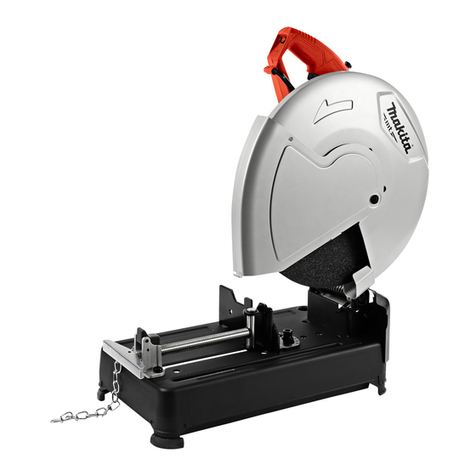
Makita 3803A User manual

MODEL
3803A
Equipped with Electric Brake
Capacities
Max cutter blade size Max. cutting depth
lf.!,~~6x
i<o;y,)
31
mm
11-7/32")
INSTRUCTION MANUAL
Overall length Net weight
No
load speed
IRPM)
9,000
411
mm
116-3116") 6.8
kg
(15
lbsl

IMPORTANT SAFETY INSTRUCTIONS
WARNING: When using electric tools, basic safety precautions should always
be followed toreduce the risk of fire, electric shock, and personal injury, includ-
ing the following:
READ ALL INSTRUCTIONS.
1.
2.
3.
4.
5.
6.
7.
8.
9.
IO.
11.
12.
13.
14.
15.
16.
2
KEEP WORK AREA CLEAN. Cluttered areas and benches invite injuries.
CONSIDER WORK AREA ENVIRONMENT. Don't use power tools in damp
or wet locations. Keep work area well
lit.
Don't expose power tools to rain.
Don't use tool in presence of flammable liquids or gases.
KEEP CHILDREN AWAY. All visitors should be kept away from work area.
Don't let visitors contact tool or extension cord.
STORE IDLETOOLS. When not inuse, tools should be stored indry, and high
or locked-up place
-
out of reach of children.
DON'T FORCETOOL.
It
willdo thejob better and safer at the ratefor which
it
was intended.
USE RIGHT TOOL. Don't force small tool or attachment to do the job of a
heavy-duty tool. Don't use tool for purpose not intended.
DRESS PROPERLY. Don't wear looseclothing or jewelry. They can be caught
in moving parts. Rubber gloves and non-skid footwear are recommended
when working outdoors. Wear protective hair covering tocontain long hair.
USE SAFETY GLASSES. Also use face or dust mask
if
cutting operation is
dusty.
DON'T ABUSE CORD. Nevercarry tool by cord or yank
it
todisconnect from
receptacle. Keep cord from heat, oil, and sharp edges.
SECURE WORK. Use clamps or a vise to hold work. It's safer than using
your hand and
it
frees both hands to operate tool.
DON'T OVERREACH. Keep proper footing and balance at all times.
MAINTAIN TOOLS WITH CARE. Keep tools sharp and clean for better and
safer performance. Follow instructions for lubricating and changing acces-
sories. Inspect tool cords periodically and if damaged, have repaired by autho-
rized service facility. Inspect extension cords periodically and replace if
damaged. Keep handles dry, clean, and free from oil and grease.
DISCONNECT TOOLS. When notin use, before servicing, and when changing
accessories, such as blades, bits, cutters.
REMOVE ADJUSTING KEYS AND WRENCHES. Form habit of checking to
see that keysand adjusting wrenches are removed from tool before turning
it
on.
AVOID UNINTENTIONALSTARTING. Don't carry tool withfinger on switch.
Be sure switch is OFF when plugging in.
OUTDOOR USE EXTENSIONCORDS. When tool is used outdoors, use only
extension cords intended for use outdoors and
so
marked.

17.
STAY ALERT. Watch what you are doing, use common sense. Don’t operate
tool when you are tired.
18.
CHECK DAMAGED PARTS. Before further use of the tool, a guard or other
part that is damaged should be carefully checked to determine that
it
will
operate properly and performitsintended function. Check for alignment of
moving parts, bindingof moving parts, breakage of parts, mounting, and any
other conditions that may affect its operation. A guard or other part that
isdamaged shouldbe properlyrepairedor replaced by anauthorized service
center unlessotherwise indicated elsewhere
in
this instruction manual. Have
defective switches replaced by authorized service center. Don’t use tool if
switch does not turn
it
on and off.
19.
GUARD AGAINST ELECTRIC SHOCK. Prevent body contact
with
grounded
surfaces. For example; pipes, radiators, ranges, refrigerator enclosures.
20.
PROPER GROUNDING. Thistoolshould be grounded while
in
use to protect
the operator from electric shock.
21.
EXTENSION CORDS: Useonly three-wire extension cords which havethree-
prong grounding-typeplugs and three-pole receptacles which accept the
tool’s plug. Replace or repair damaged or worn cord immediately.
VOLTAGE WARNING: Before connectingthetool toa power source (receptacle,
outlet, etc.) be sure the voltage supplied is the same as that specified on the
nameplate of the tool. A power source
with
voltage greater thanthat specified
for the tool can result
in
SERIOUS INJURY to the user
-
as well as damage
to
the tool. If
in
doubt, DO NOT PLUG IN THE TOOL. Using a power source
with
voltage less than the nameplate rating is harmful
to
the motor.
3

ADDITIONAL SAFETY RULES
1.
Inspect for and remove nails or foreign matter from the workpiece before
2.
Check the cutter blade carefully for cracks or damage before operation.
3.
Secure the workpiece firmly.
4.
Do not wear gloves during operation.
5.
Hold the tool firmly with both hands.
6.
Keep hands away fromthe undersideof the belt cover and the cutter blade.
Also keep the cord away from them.
7.
Never force the tool or cut too fast for existing conditions.
8.
Release the switch immediately if the cutter blade binds or the tool stalls.
9.
Never remove the tool from a cut while the cutter blade is rotating.
operation.
Replace cracked or damaged cutter blade immediately.
IO.
Never leave the tool running unattended.
11.
Never attempt to cut
with
the tool held upside down
in
a vise. This is
extremely dangerous and can lead to serious accidents.
12.
Switch off and unplug the tool and wait for the cutter blade to come to
a
complete stop beforeremovingwood chips if wood chips arejammed
in
the
chip chute. Always use a wooden stick, etc. to remove them.
SAVE THESE INSTRUCTIONS.
4

WARNING:
Always be sure that the tool
is
switchedoff and unplugged before performing any adjust-
ments or installing accessories.
Adjusting depth
of
cut
Loosen the knob on the belt cover. Move
the handle
up
or
down untilthe indication
plate indicatesthe graduation
for
the depth
of
cut desired. The tighten the knob secure-
ly.
Each increment on the depth indicator
indicates
3
mm (1/8") cuttingdepth.
Cuttingposition
This tool may be operated with conven-
tional cutter blades, four teeth cutter
blades for grooving or dado cutter blades.
There are two arrows on the scale plate
located on the front edge of the tool's base
plate. The arrow on the cutter cover side is
for conventional cutter bladesor four teeth
cutter blades. The arrow on the belt cover
side is for dado cutter blades. Align the
appropriate arrow with the cutting line.
These arrows are to be used to guide along
your desired cutting line. They accurately
\
Knob
blades and four
tethcutter blades
Arrow for dado
cutter blades
indicate the leftedge of
your
cut
as
you are cutting.The width of cut may vary according
to the width of cuttter blade selected.
(3
mm; 1/8" per graduation
on
the
scale
plate)
Guide rule
The handy guide rule allows
you
to make
accurate straight cuts parallel to
a
straight
edge
of
a
workpiece. Loosen the wing bolt
which secures the guide rule. Align the ap-
propriate arrow on the scale platewith the
cutting line. Move the guide rule until it
contacts the side of the workpiece. Tighten
the wing bolt tosecure the guide rule.
5

Switch action
To start the tool, simply pull the trigger.
Release the trigger tostop. For continuous
operation, pull the
trigger
and then push in
the lock button. To stop the tool from the
locked position, pull the trigger fully, then
release
it.
I
Lock
button
WARNING:
Before plugging in the tool, always check to
see
that the trigger switch actuates properly
and returns tothe "OFF" position when released.
Operation
WAR NlNG
:
*Be sure to clamp or secure the workpiece before cutting. It allows both hands to grip
both handles. This helps to maintain secure control of the tool
-
especially if
a
kick-
back occurs.
*Always be sure that the cutter blade
is
securedfirmly before cutting.
Rest
the front end of the tool base on the
workpiece surface and align the arrow on
the scale plate with the cutting line with-
out the cutter blade making any contact
with the workpiece. Switch on and wait
until the cutter blade attains full speed.
Then move the tool gently forward. Hold
the tool base flush with the workpiece
at
all
times. Be alert and maintain firm con-
trol of the tool
by
holding both handles
securely.
Do
not cut "one-handed". When
the cut
is
complete, do not move the tool
away from the workpiece until the cutter
blade has coasted to
a
complete stop.
NOTE
:
Cutting
line
The cutter blade does not contact the workpiece untilthe ribon the tool base passes the
end of the workpiece.
6

Shiplappingattachment
Use the shiplapping attachment when cut-
ting the edge of the workpiece. Attach the
shiplapping attachment to the guide rule
using the screws.
Align the right side of the cutter blade with
the cutting line. Move the guide rule until
the shiplapping attachment contacts the
side of the workpiece. Then tighten the
wing boltfirmly tosecure the guide rule.
Guide
rule
/
/
Shiplappingattachment
Removing
or
installingcutter blade
WARNING
:
Always be sure that the tool is switched off and unpluggedbefore removingor installing
the cutter blade.
To
remove the cutter blade, loosen the
wing bolt and take off the cutter cover.
Hold the outer flange with wrench
21
and
loosen the hex nut with wrench 19
by
turning counterclockwise. Remove the hex
nut, outer flange and cutter blade.
\
Loosen
7

To
install the cutter blade, mount the
flange, cutter blade, flange and hex nut
onto the spindle in that order, making
sure that the cutter blade
is
installed with
teeth pointingup
at
the front of the tool.
WARNING:
Remove
all
wood chips or foreign matter adhering to the spindle, flanges, etc. before
instal
I
i
ng the cutter blade.
Hex nut
Flange Flange
When using cutter blades
7.5
mm
(5/16”)
wide or
less,
install
a
flange
35
betweenthe
cutter blade and the flange
as
shown inthe
figure.
Flange Cutter blade
Use the two wrenches to tighten the hex
nut securely.
8

Side
plates
WARNING:
Always make sure that the tool
is
switched off and unplugged before installing, removing
or adjustingthe side plates.
The side plates help to prevent splintering of workpieces.This tool
is
equippedwith two
side plate
21-30
(originally installed on the tool),
a
side plate
2.4-
18
(provided
as
a
standard equipment) and
a
side plate
33-
46
(provided
as
a
standard equipment). Use the
correct combination for the cutter bladetobe used. Refer tothe table below.
Width
of
cutter blade to be used
2.4
mm
-
18
mm
21
mm
-
30
mm
(13/16"
-
1-3/16")
33
mm
-
46
mm
On cutter cover side
Side plate 2.4
-
18
Side plate 21
-
30
Side plate
33
-
46
(3/32"
-
23/32")
(1-5/16"
-
1-13/16")
On belt cover side
Side plate 21
-
30
Side plate 21
-
30
Side plate 21
-
30
When installing the side plates, adjust them
so
that the clearances between the side of
the cutter blade and the side plates
are
approx.
0.1
mm
(0.004").
Slowly revolve
the cutter blade by turning the drive
belt by hand to make sure that the clear-
ances
are
adequate. There must be no con-
tact when rotated.
Adjusting the indicationplate
WARNING
:
Always make sure that the tool
is
switched off and unplugged before makingany adjust-
ments.
Adjust the indication plate
as
follows when
replacing the cutter blade. Loosen the
knob on the belt cover. Move the handle
up or down until the cutter blade tips are
flush with the underside of the tool base
while revolving the cutter blade by turning
the drive belt by hand. Then tighten the
knob securely. Adjust the indication plate
so
that
it
points tothe
"0"
graduation.
When usingcutter blades
120
mm
(4-3/4") india.
Depth indicator
9

When using cutter blades
110
mm
(4-3/8')
in diameter, simply re-install the indication
plate upside down and adjust
it
so that
it
pointstothe
"0'
graduation.
When usingcutter blades
110
mm
(4-3/8")
in
dia.
Indicationplate
/
-
I
Adjusting the scale plate
WARNING:
Always make sure that the tool
is
switched off and unplugged before making any adjust-
ment.
Adjust the scale plate
as
follows when
using cutter blades
13.5
mm
(9/16')
wide
or
less.
Loosen the screws which secure the
scale
plate. Adjust the scale plate right or
left
so
that the arrow on the scale plate is
aligned with the side of the cutter blade
using the guide rule
as
shown in the figure.
Tighten the screws securely.
Scale plate Cutter blade
Miter guide rule (optional accessory)
WARNING:
Always make sure that the tool
is
switched off and unpluggedbefore making any adjust-
ments.
Loosen the wing bolt on the miter guide
rule. Place the miter guide rule on the
workpiece and adjust
it
so
that the ege
of
the miter guide rule
is
aligned with the cut-
ting line. Securely tighten the wing bolt on
the miter guide rule. Then position the
miter guide rule
so
that the arrow on the
scale plate on the tool
is
aligned with the
cutting line. Secure the miter guide rule
by stepping on the foot plate on the miter
guide rule. Move the tool gently forward
along the miter guide rule. Be especially careful to maintain proper balance and footing,
or
else
loss
of control and subsequent injury may result.
10

Also, the miter guide rule position can be
determined using
the
indicator on
the
miter guide rule. Adjust the indicator
so
that
its
length
is
0.5
mm (0.02”) shorter
than the distance (A)between the edge of
the tool base and the side
of
the cutter
blade. With
this
adjustment,
the
indicator
will project toward the cutter blade within
0.5
mm
(0.02”)
of
it
as
the edge of the
tool slides along the edge of the miter
guide rule. Secure the miter guide rule
at
the position where the indicator tip
is
0.5
mm
(0.02”)
away fromthe cutting line.
?<:
mm
(0.02”)
Cutter blade
indicator
CAUTION
:
Unplug the tool and re-adjustthe indicator when changing the miter angle of the miter
guide rule.
Dado cuttingguide rule (optionalaccessory)
WARNING
:
Always make sure that the tool
is
switched off and unplugged before makingany adjust-
ments.
Firmly clamp
a
straight board to the work-
piece parallel to the cutting line and use
it
as
a
guide against the dado cutting
guide rule. Adjust the dado cutting guide
rule
so
that the arrow on the scale plate
is
aligned with the cutting line. The best
distance between the cutting line and the
guide (straight board)
is
approx. 150 mm
(5-29/32”).
Cutting line
Approx.
150
mm
(5-29/32”)
11

MAINTENANCE
CAUTION
:
Always be sure that the tool is switched off and unpluggedbefore attempting to perform
inspection or maintenance.
Replacingcarbon brushes
Remove and check the carbon brushes
regularly. Replace when they wear down
to the limit mark. Keep the carbon brushes
clean and free to slip in the holders. Both
carbon brushes should be replaced
at
the
same time. Use only identical carbon
brushes.
Use
a
screwdriver to remove the brush
holder caps. Take
out
the worn carbon
brushes, insert the new ones and secure the
brushholder caps.
/
Limit
mark
To maintain product SAFETY and RELIABILITY, repairs, any other maintenance or
adjustment should be performed by Makita Authorized or Factory Service Centers,
always using Makita replacementparts.
12

ACCESS0
R
I
ES
CAUTION
:
These accessories or attachments are recommended for
use
with your Makita tool specified in this
manual. The
use
of
any other accessories
or
attachments might present
a
risk
of
injury to persons.
The accessories or attachments should
be
used only in the proper and intended manner.
0
Cutter blade
Dia. 120
mm
(4-3/4")
793022-4 3.0 (1/8")
793024-0 3.9 (5132")
793025-8 4.5 (3/16")
793026-6 5.5 (7/32")
+
793027-4 6.0 (114")
793030-5 10.5 (7116")
793031-3 12.0 (1/2")
i
793032-1 13.5 (9116")
793039-7
I
15.0 (5/8")
793040-2
I
16.5 (11/16"1
793041-0 18.0 (314")
793042-8 21.0 (7/8')
+
793043-6 30.0 (1-1
/8")
For dado cutting
Dia. 110
mm
(4-3/8")
0
Guide rule
Part
No.
164191-2 (Forgroove cutting)
Part
No.
164582-7 (For dado cutting)
793320-6
I
10.5 (7/16')
793298-3
1
12.0 (112")
793321-4
I
13.5 (9/16")
793129-6
I
15.0 (5/8')
0
Shiplapping scale
Part
No.
192270-6
0
Miter guide rule (Angle
guide)
Part
No.
192318-4
13

0
Flange
35
.Wrench
Part
No.
224051-1 #19 Part
No.
781206-6
[For cutter blade width 2.4
mm
(3/32")
-
#21 Part
No.
781208-2
7.5
mm
(5/16")1
0
Screwdriver
Part
No.
783002-8
0
Wooden carrying case
Part
No.
822175-0
14

Jan
-18-'93
EN
GROOVE CUTTER
Model
3803A
Note: The switch, noise suppressor and other part configurations
may differ from country to country.
15

MODEL 3803A Jan.-18-'93 EN
MACHINE
35
36
31
38
39
40
41
42
43
44
45
46
41
48
49
50
51
52
53
54
55
56
57
58
59
60
61
62
63
64
65
66
~
'y$
$tD
DESCRIPTION
1
1
1
3
1
1
1
1
3
1
1
1
1
1
2
1
1
1
1
2
1
2
1
1
1
1
1
2
2
1
2
2
MACHINE
~
10
11
12
13
14
15
16
17
18
19
20
21
22
23
24
25
26
21
28
29
30
31
32
33
34
V
Pulley 9-49
Pan
Head Screw
M4x8 (With Washer]
Inner
cover
Pen
Head
Screw
M4x8 IWith Washer)
Pointer
Grip 30
Pan
Head
Screw
M6x40 IWifh Washerl
Brush
Holder
Cap
Carbon
Brush
Pan
Head
Screw
M4x18 (With Washer)
Switch
Noise
Suppressor
Insulation
Washer
Pan
Head
Screw
M4x8 IWith Washer)
Handle
Cover
Pan
Head
Screw
M4x18 IWith Washer)
Strain
Relief
Cord Guard
Cord
Motor Housing
Screw
M6x25
cutter Cover
Name
Plate
Hex
Nut
M8
Poly
V
Belt 9-362
Belt
Cover
Pan
Head
Screw
M5x40 IWith Washer1
Knob
40
Ball
Bearing
6201LLB
Spindle
Ball
Bearing
6302LLB
Bearing
Box
Flange
35
Cutter
Blade
11
21
31
41
51
61
72
82
92
4
1
1
2
1
1
2
1
1
1
1
1
1
1
1
1
1
1
1
1
1
1
1
1
1
Flange
35
Hex
Nut
M12
Makita Mark
Pan
Head
Screw
M5x20 (With Washerl
Bracket
Ball
Bearing
6200LLB
Fan
83
ARMATURE ASSEMBLY
(With
Item
40
-
42 44
&
451
Countersunk
Head
Screw
M4x12 IWifhWasher)
Flat Washer
12
Ball
Bearing 6201LLB
V
Pulley
9-21
ILL
Baffle Plare
FIELD ASSEMBLY
Pan
Head
Screw
M5x65 (With Washer1
Rod
10
Pan
Head
Screw
M5x12
Compression
Spring
7
Screw
M6x25
Pan
Head
Screw
M4x6 (With Washerl
Scale
Plate
Pan
Head
Screw
M4x8 IWith Washerl
Scale
Plate
Screw
MBx25
Compression
Spring
7
Base
Side
Plale
IRI
Side
Plate
Retainer
Countersunk
Head
Screw
M4xl2
Side
Plate
IRi
Side
Plate Retainer
Countersunk
Head
Screw
M4x12
Note: The
switch.
noise
suppressor
and
other
part specificatcons
may
differ
from Country 10
country.
Makita Corporation
3-11
-8, Sumiyoshi-cho,
Anjo,
Aichi
446
Japan
883844A1
PRINTED
IN
JAPAN
1993
-
6E
Other manuals for 3803A
1
Table of contents
Other Makita Cutter manuals

Makita
Makita DMC300 User manual

Makita
Makita 4190D User manual

Makita
Makita EK7650H User guide

Makita
Makita CE001G User manual

Makita
Makita DCC501 User manual

Makita
Makita DCS552 User manual

Makita
Makita 4191DZ User manual

Makita
Makita CE001GT202X20 User manual

Makita
Makita 4191DZ User manual

Makita
Makita CP100D User manual

Makita
Makita EK7650H User guide

Makita
Makita 4131 User manual

Makita
Makita DCS551 User manual

Makita
Makita DSC121 User manual

Makita
Makita M2401 User manual

Makita
Makita DCE090 User manual

Makita
Makita 4101RH User manual

Makita
Makita 3803A User manual

Makita
Makita CS002GZ01 User manual

Makita
Makita SC103D User manual