Understanding the Module Status LEDs
Enter the connection information:
The default static IP address is: 192.168.200.1. The IP address is
also visible from the built-in display on the front of the unit.
The default user name is: admin.
The default password is: !Exfo123.
Configuring Your Unit At First Startup Inserting Modules
1
2
Place the module vertically so that the connector pins are at the back, and the protruding edges are on
the left.
Insert the protruding edges of the module into the grooves and push all
the way to the back.
Note: There is no need to turn off your unit before inserting a
module.
Turn the two retaining screws clockwise to secure the module in place.
Its faceplate should be flush with the front panel of the unit.
Press to turn the unit on.
Note: You may have to modify the IP address of the
computer to make sure that the computer and
unit can “see” each other. The IP address of the
computer must be within the same range of
addresses as the IP address of the unit
(ex.: 192.168.200.20).
Note: If several units are connected to the same
network with the default static IP address, you
may have to modify the IP addresses of these
units to avoid connection problems (not
accessing the right unit).
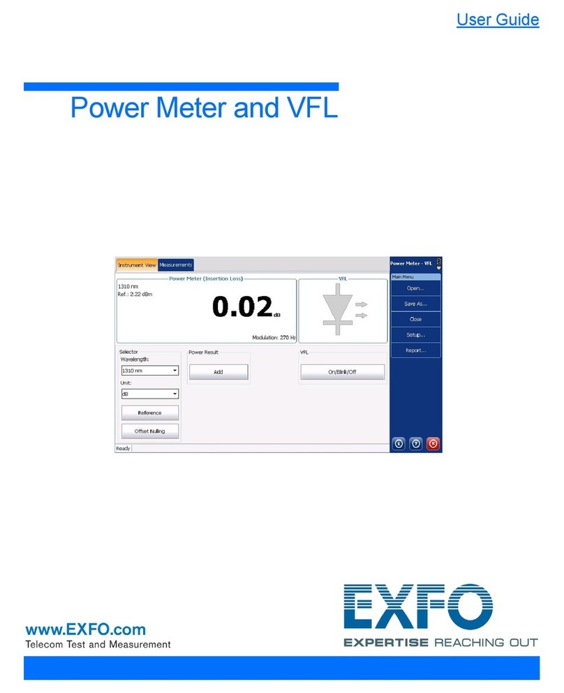
8On the computer, start the AMT Remote Access application.
9
10
Click to have access to the unit and
the applications exactly as if you
were in front of the unit with a
monitor, a keyboard, and a mouse
connected to it.
11 Follow the on-screen instructions. The user documentation will be accessible during the setup.
1From a computer (laptop), go to http://www.exfo.com/software/exfo-apps.
2Under PC Software, look for the
AMT Remote Access application, and download it.
3Double-click the file that you have just downloaded to
start the installation, and follow the on-screen
instructions.
CAUTION
To avoid damaging your unit, use it only with modules
approved by EXFO (refer to the unit’s technical
specifications).
H/S (blue LED)
³Blinking: The module is in a transition state (being prepared for removal, or being
detected by the system).
³Steady: The module can be removed safely.
IN USE (green LED)
³Blinking: A test or a measurement, using the module, is underway.
³Steady: The module is in use.
ERROR (red LED)
Steady: The module is in error.
Current IP address of the unit
If necessary, press the activation
button.
5
Connect the provided power
cord to the unit and a power
outlet.
Flip the main power switch
to the On position.
7
3
4
Display activation button
6Connect one end of a network cable to the management port of
the unit ( ) and the other end to an Ethernet port of the
computer.
