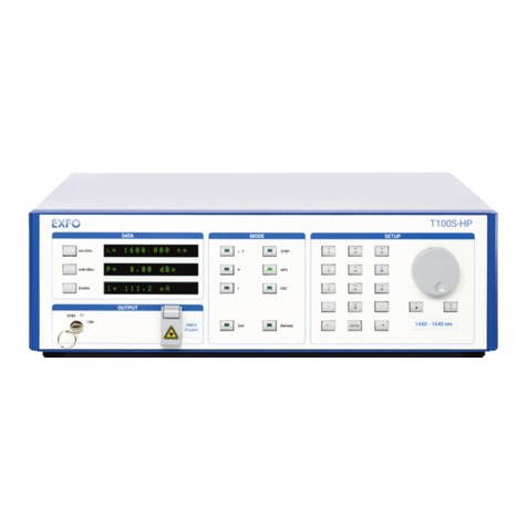
EXFO T500S User manual

User Guide
T200S/T500S
Tunable Laser Source
www.EXFO.com

Copyright Information
ii T200S/T500S
Copyright Information
Copyright © 2021–2023 EXFO Inc. All rights reserved. No part of this publication may be
reproduced, stored in a retrieval system or transmitted in any form, be it electronically,
mechanically, or by any other means such as photocopying, recording or otherwise,
without the prior written permission of EXFO Inc.(EXFO).
Information provided by EXFO is believed to be accurate and reliable. However, no
responsibility is assumed by EXFO for its use nor for any infringements of patents or other
rights of third parties that may result from its use. No license is granted by implication or
otherwise under any patent rights of EXFO.
EXFO’s Commerce And Government Entities (CAGE) code under the North Atlantic Treaty
Organization (NATO) is 0L8C3.
The information contained in this publication is subject to change without notice.
Trademarks
EXFO’s trademarks have been identified as such. However, the presence or absence of
such identification does not affect the legal status of any trademark.
Units of Measurement
Units of measurement in this publication conform to SI standards and practices.
Patents
The exhaustive list of patents is available at www.EXFO.com/patent.
Document version: 3.0.0.2
Information in this document applies to the T200S/T500S embedded software package
version 3.0.x (and system image version 3.0.x).

Contents
Tunable Laser Source iii
Contents
Copyright Information .........................................................................................................................................ii
Regulatory Information .......................................................................................................................................v
1 Introducing the T200S and T500S Laser Sources .................................................................1
Technical Specifications .......................................................................................................................................1
T200S/T500S Overview ........................................................................................................................................2
Conventions .........................................................................................................................................................6
2 Safety Information ................................................................................................................7
Laser Safety Information ......................................................................................................................................8
Other Safety Symbols on Your Unit .....................................................................................................................9
Electrical Safety Information ..............................................................................................................................10
3 Getting Started with Your T200S/T500S .............................................................................13
Unpacking and Installing the T200S/T500S ........................................................................................................13
Connecting the T200S/T500S to a Power Source ...............................................................................................14
Connecting External Optical Devices to the T200S/T500S ..................................................................................15
Connecting a Mouse and Keyboard to the T200S/T500S ...................................................................................16
Turning on the T200S/T500S and Accessing the GUI .........................................................................................16
Turning off the T200S/T500S .............................................................................................................................18
4 Setting Up Your T200S/T500S ..............................................................................................19
Defining the Display Colors and Language ........................................................................................................19
Adjusting the Volume ........................................................................................................................................20
Setting the Date and Time .................................................................................................................................21
Connecting the T200S/T500S to your Company Network ..................................................................................22
Renaming the Instrument ..................................................................................................................................23
Handling User Configuration .............................................................................................................................24
5 Setting the Emission Wavelength/Frequency ....................................................................27
Defining the Spectral Unit .................................................................................................................................27
Tuning the Emission Wavelength or Frequency .................................................................................................28
Performing a Sweep Sequence ..........................................................................................................................32
Performing Internal Wavelength Referencing ....................................................................................................40
Monitoring the Wavelength Electrical Level .......................................................................................................41
6 Modifying the Optical Power .............................................................................................43
Enabling/Disabling the Laser Output ..................................................................................................................43
Defining the Power Unit ....................................................................................................................................44
Setting the Optical Output Power (T500S models only) .....................................................................................44
Monitoring the Laser Output Power ..................................................................................................................45
7 Remotely Controlling the T200S/T500S ..............................................................................47
Setting the T200S/T500S Ethernet Port ..............................................................................................................47
Entering/Exiting the Remote Mode ....................................................................................................................48
Communication Principle ...................................................................................................................................49
Writing Remote Control Code: Examples ...........................................................................................................57
8 Maintenance ........................................................................................................................75
Cleaning the T200S/T500S .................................................................................................................................75
Cleaning the Optical Connector .........................................................................................................................76
Updating the T200S/T500S System Version .......................................................................................................78
Updating the Operating System Version ............................................................................................................79
Replacing Fuses .................................................................................................................................................80
Recalibrating the T200S/T500S ..........................................................................................................................81
Recycling and Disposal ......................................................................................................................................81

Contents
iv T200S/T500S
9 Troubleshooting .................................................................................................................. 83
Solving Common Problems ................................................................................................................................83
Forcing the T200S/T500S to Shutdown & Restart ..............................................................................................83
Abruptly Turning off the T200S/T500S (Emergency Shutdown) .........................................................................83
Restoring Your Unit to Normal Operation ..........................................................................................................84
Using Assistance Tools .......................................................................................................................................86
Viewing System Information ..............................................................................................................................87
Displaying the User Documentation ..................................................................................................................87
Contacting the Technical Support Group ...........................................................................................................87
Transportation ...................................................................................................................................................88
10 Warranty .............................................................................................................................. 89
General Information ..........................................................................................................................................89
Gray Market and Gray Market Products .............................................................................................................89
Liability ..............................................................................................................................................................90
Exclusions ..........................................................................................................................................................90
Certification .......................................................................................................................................................90
Service and Repairs ............................................................................................................................................91
EXFO Service Centers Worldwide .......................................................................................................................92
A SCPI Command Reference .................................................................................................. 93
General Commands ...........................................................................................................................................93
T200S/T500S Specific Commands ....................................................................................................................102

Regulatory Information
Tunable Laser Source v
Regulatory Information
USA Electromagnetic Interference Regulatory Statement
Electronic test and measurement equipment is exempt from FCC part 15, subpart B
compliance in the United States of America. However, EXFO Inc. makes reasonable efforts
to ensure compliance to the applicable standards.
The limits set by these standards are designed to provide reasonable protection against
harmful interference when the equipment is operated in a commercial environment. This
equipment generates, uses, and can radiate radio frequency energy and, if not installed and
used in accordance with the user documentation, may cause harmful interference to radio
communications. Operation of this equipment in a residential area is likely to cause
harmful interference in which case the user will be required to correct the interference at
his own expense.
Modifications not expressly approved by the manufacturer could void the user’s authority to
operate the equipment.
Canada Electromagnetic Interference Regulatory Statement
This equipment generates, uses, and can radiate radio frequency energy and, if not
installed and used in accordance with the instruction manual, may cause harmful
interference to radio communications. Operation of this equipment in a residential area is
likely to cause harmful interference.
Cet équipement génère, utilise et peut émettre de l'énergie radio-fréquence et, s'il n'est pas
installé et utilisé conformément à la documentation de l'utilisateur, il peut occasionner une
interférence néfaste aux communications radio. L'utilisation de cet équipement dans une
zone résidentielle est susceptible d'occasionner une interférence néfaste.
Caution: This equipment is not intended for use in residential environments and may not
provide adequate protection to radio reception in such environments.
Attention: Cet appareil n'est pas destiné à être utilisé dans des environnements résidentiels
et peut ne pas assurer la protection adéquate à la réception radioélectrique dans ce type
d'environnements.
This is a class A, group 1 product.
³Class A equipment: Equipment that is, by virtue of its characteristics, highly unlikely to
be used in a residential environment, including a home business shall be classified as
class A and shall comply with the class A limits specified in the applicable ICES
standard. Characteristics considered in this assessment include price, marketing and
advertising methodology, the degree to which the functional design inhibits
applications suitable to residential environments, or any combination of features that
would effectively preclude the use of such equipment in a residential environment.
Classe A: Matériel qui, en raison de ses caractéristiques, ne sera fort probablement pas
utilisé dans un milieu domiciliaire ni par des entreprises établies à domicile. Parmi les
caractéristiques considérées dans cette évaluation, il y a le prix, les méthodes de
commercialisation et de publicité, la mesure dans laquelle les fonctions de l'appareil
font qu'il ne se prête pas à des applications convenant au milieu domiciliaire ou toute

Regulatory Information
vi T200S/T500S
combinaison de ces caractéristiques qui aurait pour conséquence d'en prévenir
effectivement l'utilisation à domicile. Utilisé également pour indiquer les limites
d'émission correspondantes qui s'appliquent à un tel matériel.
³Group 1 equipment: group 1 contains all equipment which is not classified as group 2
equipment, and includes equipment such as laboratory and scientific equipment,
industrial process, measurement and control equipment.
Group 2 equipment: group 2 contains all ISM RF equipment in which radio-frequency
energy in the frequency range 9 kHz to 400 GHz is intentionally generated and used or
only used locally, in the form of electromagnetic radiation, inductive and/or capacitive
coupling, for the treatment of material for inspection/analysis purposes, or for transfer
of electromagnetic energy.
Appareils du groupe 1 : le groupe 1 réunit tous les appareils compris dans le domaine
d’application de la présente Norme, qui ne sont pas classés comme étant des appareils
du groupe 2. Le groupe 1 inclut les appareils scientifiques et de laboratoire, les
processus industriels, appareils de mesure ou de contrôle.
Appareils du groupe 2 : le groupe 2 réunit tous les appareils ISM à fréquences
radioélectriques dans lesquels de l’énergie à fréquences radioélectriques dans la plage
de fréquences comprises entre 9 kHz et 400 GHz est produite et utilisée volontairement
ou uniquement utilisée localement sous forme de rayonnement électromagnétique, de
couplage inductif et/ou capacitif, pour le traitement de la matière, à des fins d’examen
ou d’analyse ou pour le transfert d’énergie électromagnétique.
Supplier's Declaration of Conformity (SDoC)
The SDoC for your product is as follows:
CAN ICES-001 (A) / NMB-001 (A)
EU and UK Electromagnetic Compatibility Regulatory
Statement
Warning: This is a class A product. In a domestic environment, this product may cause radio
interference in which case the user may be required to take adequate measures. Your
product is suitable for use in industrial electromagnetic environments.
EU and UK Declaration of Conformity
The full text of the declaration of conformity is available at the following Internet address:
www.exfo.com/en/resources/legal-documentation.
EU Economic Operator
EXFO Solutions SAS
2, rue Jacqueline Auriol,
Saint-Jacques-de-la-Lande,
35091 Rennes Cedex 9
FRANCE

Tunable Laser Source 1
1 Introducing the T200S and T500S
Laser Sources
The T200S and T500S are continuously tunable laser sources that cover all major bands of
telecom application from the O-band to the U-band (depending on the model).
The embedded software enables you to control the product operations through a graphical
user interface or through remote commands and queries.
Technical Specifications
This section describes the T200S/T500S technical specifications and requirements.
Optical Measurement Specifications
To obtain this product’s most recent technical specifications, visit the EXFO Web site at
www.exfo.com.
Hardware Specifications
Hardware
Interfaces for
External Devices
USB-A 2.0 (x2) Mouse, keyboard, or USB key for software
update
USB-A 3.0 (x1)
Remote Interface Ethernet RJ45 (x1) 1 Gbit/s. A shielded Ethernet cable is required.
Electrical
Interfaces
In (BNC) Trig in 0-5 V TTL
Out (BNC) Trig out 0-5 V TTL
Power out 0-5 V TTL: 0-10 mW
16 bits DAC
λout 0-5 V TTL: λMin to λMax
16 bits DAC
Maximum cable length 10 m (32.8 ft)
Electrical
Specifications
Input power see Electrical Safety Information on page 10.
Fuses (x2) T4AH250V
Maximum power
consumption
72 W
Physical
Specifications
Dimensions (H x W x D) 173 mm x 217 mm x 473 mm
(6.8 in x 8.5 in x 18.6 in)
Weight 9 kg (19.8 lb)

Introducing the T200S and T500S Laser Sources
2T200S/T500S
T200S/T500S Overview
The T200S/T500S is delivered with the following accessories:
³1 power supply cable,
³1 patchcord,
³1 printed manual Getting Started with T200S/T500S,
³1 USB key containing the system package version installed on your T200S/T500S,
remote examples (if any) and user documentation.
Front panel
On/Off button
The On/Off button enables you to turn on or off the T200S/T500S (see Turning on the
T200S/T500S and Accessing the GUI on page 16 andTurning off the T200S/T500S on
page 18).
Status LEDs
The status led is lit if the laser diode is enabled.
Touch screen
The touch screen enables you to perform all possible operations on the T200S/T500S.
On/Off button
Speaker
Touch screen
Status LEDs
Optical output
Air intake holes
Laser model

Introducing the T200S and T500S Laser Sources
Tunable Laser Source 3
T200S/T500S Overview
Speaker
The T200S/T500S emits a sound when you enable or disable the laser diode and when you
modify the laser parameters.
For more details, see Adjusting the Volume on page 20.
Optical output connector
The FC/APC optical output connector is protected by a safety cap.
The laser warning symbol indicate the location of the laser source. For more details, see
Laser Safety Information on page 8.
Rear panel
BNC Connectors
The BNC connectors enable you to synchronize T200S/T500S sweeps with external
instruments (see Hardware Specifications on page 1 for more details on signal levels).
³Trig in: input BNC connector for starting sweep in synchronization with an external
trigger input signal. For more details, see Triggering the Sweep Sequence on page 37.
³Trig out: output BNC connector for outputting a trigger signal during
wavelength/frequency emission. For more details, see Generating an Output Trigger
Signal during Emission on page 31 and Generating an Output Trigger Signal During
Sweep on page 39.
USB-A 3.0
port
Cooling fan
Fuse Drawer
Power Switch
Power Cable
Connector
Input
Trigger
BNC Connectors
USB-A 2.0
port (x2)
Ethernet port
Output
Trigger
Power
out λout

Introducing the T200S and T500S Laser Sources
4T200S/T500S
T200S/T500S Overview
³Power out: output BNC connector for power monitoring. For more details, see
Monitoring the Laser Output Power on page 45.
³λOut: output BNC connector for wavelength monitoring. It provides an analog reading
related to the wavelength in nm. For more details, see Monitoring the Wavelength
Electrical Level on page 41.
USB-A Ports
The label identifies the USB-A 3.0 ports, the identifies the USB-A 2.0 ports.
These ports enable you to connect USB devices such as:
³a keyboard and mouse if needed
³a USB key for software update
For more details on USB connections, see Connecting a Mouse and Keyboard to the
T200S/T500S on page 16.
Ethernet Port
The label identifies the Ethernet port, which enables you to:
³Connect the T200S/T500S to your network. For more details, see Connecting the
T200S/T500S to your Company Network on page 22.
³Perform remote control operations on the T200S/T500S. For more details, see Remotely
Controlling the T200S/T500S on page 47.
Cooling Fan
The cooling fan extract warm air from inside (air enters in front of the T200S/T500S). A
cover grid protects the fan.
Power Input
The power input part includes the following elements:
³Power Switch
³Power Cable Connector
The product is equipped with a self-regulating power supply.
³Fuse Drawer
The fuse drawer contains two fuses to protect the product from overcurrent (for fuse
type, see Hardware Specifications on page 1).
For details on how to replace the fuses, see Replacing Fuses on page 80.

Introducing the T200S and T500S Laser Sources
Tunable Laser Source 5
T200S/T500S Overview
Labels and Markings
Label Description
Identification of the product.
Manufacturer identification.
Contact information of the manufacturer.
Fuse type.
See Hardware Specifications on page 1.
Indicates an injury hazard. It appears on a location that
requires special instructions for proper use: see
Electrical Safety Information on page 10.
WEEE symbol for recycling.
See Recycling and Disposal on page 81.
Safety certification label.
CAN ICES-001 (A) /
NMB-001 (A)
Canadian certification.
See Regulatory Information on page v.
UK conformity assessment.
See Regulatory Information on page v.
CE marking.
See Regulatory Information on page v.
Laser safety label
The product is a class 1M laser product. For more details,
see Laser Safety Information on page 8.
EFUP label (RoHS China)
See Chinese Regulation on Restriction of Hazardous
Substances (RoHS) on page 165.
Windows license label.
The T200S/T500S embeds Windows 10.
Warranty seal.
The T200S/T500S cover must not be open, otherwise the
warranty is not valid anymore.
MANUFACTURED / FABRIQUE
OPTIONS
MODEL / MODELE
Made in France
xxxx-xx
T200S
xxxxxxxxxxxx
SERIAL NUMBER / NUMERO DE SERIE

Introducing the T200S and T500S Laser Sources
6T200S/T500S
Conventions
Conventions
Before using the product described in this guide, you should understand the following
conventions:
WARNING
Indicates a potentially hazardous situation which, if not avoided, could result in
death or serious injury. Do not proceed unless you understand and meet the
required conditions.
CAUTION
Indicates a potentially hazardous situation which, if not avoided, may result in
minor or moderate injury. Do not proceed unless you understand and meet the
required conditions.
CAUTION
Indicates a potentially hazardous situation which, if not avoided, may result in
component damage. Do not proceed unless you understand and meet the required
conditions.
IMPORTANT
Refers to information about this product you should not overlook.

Tunable Laser Source 7
2 Safety Information
WARNING
Do not install or terminate fibers while a light source is active. Never look directly
into a live fiber and ensure that your eyes are protected at all times.
WARNING
The use of controls, adjustments and procedures, namely for operation and
maintenance, other than those specified herein may result in hazardous radiation
exposure or impair the protection provided by this unit.
WARNING
If the equipment is used in a manner not specified by the manufacturer, the
protection provided by the equipment may be impaired.
WARNING
Use only accessories designed for your unit and approved by EXFO. For a complete
list of accessories available for your unit, refer to its technical specifications or
contact EXFO.
IMPORTANT
Refer to the documentation provided by the manufacturers of any accessories used
with your EXFO product. It may contain environmental and/or operating conditions
limiting their use.
IMPORTANT
When you see the following symbol on your unit , make sure that you refer
to the instructions provided in your user documentation. Ensure that you
understand and meet the required conditions before using your product.
IMPORTANT
When you see the following symbol on your unit , it indicates that the unit is
equipped with a laser source, or that it can be used with instruments equipped
with a laser source. These instruments include, but are not limited to, modules and
external optical units.

Safety Information
8T200S/T500S
Laser Safety Information
Your instrument is in compliance with standard IEC 60825-1: 2014.
Laser radiation may be encountered at the optical output port.
The following label indicates that the product contains a Class 1M source:
Wavelength range (overall models): / Plage de longueur d'onde (ensemble des modèles) :
1240-1680 nm
For each model, wavelength range is shorter and depends on model (see specification
sheet for details) / Pour chaque modèle, la plage de longueur d'onde est plus courte et
dépend du modèle (voir détails dans la fiche technique du produit).
Pout max.: / Psortie max. : ≤50 mW
IMPORTANT
Other safety instructions relevant for your product are located throughout this
documentation, depending on the action to perform. Make sure to read them
carefully when they apply to your situation.
WARNING
Viewing the laser output with telescopic optical instruments (for example,
telescopes and binoculars) may pose an eye hazard and thus the user should not
direct the beam into an area where such instruments are likely to be used.
RAYONNEMENT LASER INVISIBLE
NE PAS OBSERVER DIRECTEMENT À L'AIDE D'INSTRUMENTS D'OPTIQUE
NE PAS EXPOSER LES UTILISATEURS DE DISPOSITIF OPTIQUE
TÉLESCOPIQUE
APPAREIL À LASER DE CLASSE 1M
INVISIBLE LASER RADIATION
DO NOT VIEW DIRECTLY WITH OPTICAL INSTRUMENTS
DO NOT EXPOSE USERS OF TELESCOPIC OPTICS
CLASS 1M LASER PRODUCT

Safety Information
Tunable Laser Source 9
Other Safety Symbols on Your Unit
One or more of the following symbols may also appear on your unit.
Symbol Meaning
Direct current
Alternating current
The unit is equipped with an earth (ground) terminal.
The unit is equipped with a protective conductor terminal.
The unit is equipped with a frame or chassis terminal.
On (Power)
Off (Power)
OR On/off (Power)
Fuse

Safety Information
10 T200S/T500S
Electrical Safety Information
This unit uses an international safety standard three-wire power cable. This cable serves as
a ground when connected to an appropriate AC power outlet.
The color coding used in the electric cable depends on the cable. New plugs should meet
the local safety requirements and include:
³adequate load-carrying capacity
³ground connection
³cable clamp
WARNING
³If you need to ensure that the unit is completely turned off, disconnect the
power cable.
³Use only the certified power cord that is suitably rated for the country where
the unit is used.
³Replacing detachable MAINS supply cords by inadequately RATED cords may
result in overheating of the cord and create a risk of fire.
WARNING
³Use this unit indoors only.
³Do not remove unit covers during operation.
³Operation of any electrical instrument around flammable gases or fumes
constitutes a major safety hazard.
³To avoid electrical shock, do not operate the unit if any part of the outer
surface (covers, panels, etc.) is damaged.
³Only authorized personnel should carry out adjustments, maintenance or
repair of opened units under voltage. A person qualified in first aid must
also be present. Do not replace any components while the power cable is
connected.
³Use only fuses with the required rated current and specified type . Do not
use repaired fuses or short-circuited fuse holders. For more information, see
the section about replacing the fuses in this user documentation.
³Unless otherwise specified, all interfaces are intended for connection to
Safety Extra Low Voltage (SELV) circuits only.
³Capacitors inside the unit may be charged even if the unit has been
disconnected from its electrical supply.

Safety Information
Tunable Laser Source 11
Electrical Safety Information
CAUTION
Position the unit so that the air can circulate freely around it.
Equipment Ratings
Temperature Operation +15 °C to +35 °C (+59 °F to +95 °F)
Storage -20 °C to +50 °C (-4 °F to 122 °F)
Performance guaranteed temperature +18 °C to +28 °C (+64.4 °F to +82.4 °F)
Relative humidity < 80% (non condensing)
Maximum operation altitude < 2000 m (6562 ft)
Pollution degree 2
Overvoltage category II
Measurement category Not rated for measurement categories II, III, or IV
Input powera
a. Not exceeding ± 10 % of the nominal voltage.
100–240 V ; 50/60 Hz; 0.65–0.3 A
CAUTION
³The use of voltages higher than those indicated on the label affixed to your
unit may damage the unit.


Tunable Laser Source 13
3 Getting Started with Your
T200S/T500S
This section explains how to properly install and connect your T200S/T500S.
Unpacking and Installing the T200S/T500S
The T200S/T500S is designed for indoor use only, and is not dedicated to wet locations. It
must be operated under proper environment conditions, as explained in the following
procedure.
This section explains how to install the T200S/T500S as a bench top instrument.
To install the T200S/T500S into a rack, EXFO provides a specific rack mount shelf (for more
details, contact your sales representative). The procedure to install the T200S/T500S into a
19" rack is available in the manual delivered with the rack mount kit.
To unpack and install the T200S/T500S:
1. Open the package with care and remove the protective foam.
2. Pull out the T200S/T500S vertically from its packaging and keep it horizontal.
3. Set the T200S/T500S on a flat stable surface free of excessive vibration.
4. Allow the flow of air to circulate freely at the front and rear of the T200S/T500S and
remove any equipment or paper that could block the air flow. Ventilation holes are
located on the front and rear sides of the T200S/T500S.
5. On the rear panel (see Rear panel on page 3), make sure the power switch is set to O.
6. To tilt the T200S/T500S upward (bench-top use only), deploy the two retractable legs
located below it, as illustrated in the following figure.
CAUTION
³Make sure the location where the T200S/T500S will be installed meets the
environmental characteristics listed in Electrical Safety Information on page 10.
³Do not install the T200S/T500S near any source of heat or cold.
³To ensure proper ventilation and cooling, make sure there is sufficient clearance
at the front and at the rear of the T200S/T500S in the place where it will be
installed.
IMPORTANT
When unpacking, handle the device with care and do not damage the original
shipping container in case the T200S/T500S needs to be returned to EXFO.

Getting Started with Your T200S/T500S
14 T200S/T500S
Connecting the T200S/T500S to a Power Source
The T200S/T500S has a chassis connected to ground via the power supply cable. A
protective ground connection by way of the grounding conductor in the power cable is
essential for safe operation.
To connect the T200S/T500S to a wall socket:
1. Make sure the power switch is set to O.
2. On the rear panel, connect the power supply cable provided with the instrument to the
mains socket located on the rear panel of the T200S/T500S.
3. Plug the other end of the power supply cable to the proper voltage wall socket outlet (to
know the voltage requirement, see Electrical Safety Information on page 10).
4. On the rear panel, set the power switch to I.
WARNING
³Make sure the wall socket on which the T200S/T500S will be plugged is
protected by a 16 A max circuit breaker.
³Make sure the T200S/T500S power source does not apply more than 265 Volts
RMS between the supply conductors and the ground.
³To avoid the possibility of injury, make sure the socket outlet in which the
power supply cable will be plugged is equipped with a protective ground
contact, and that the electrical installation fulfills the local safety requirements.
This manual suits for next models
1
Table of contents
Other EXFO Measuring Instrument manuals