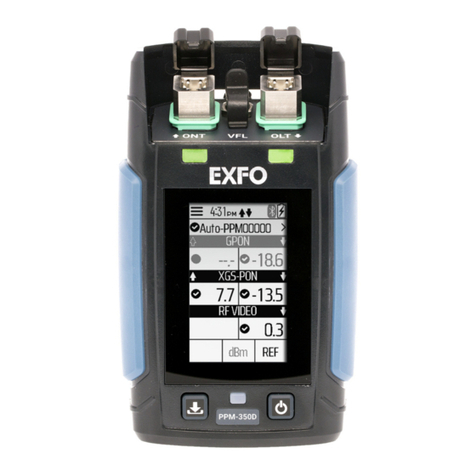
EXFO OSA20 User manual

Getting Started
Optical Spectrum Analyzer
OSA20
Optical Spectrum Analyzer
www.EXFO.com

Contents
ii OSA20
Contents
1 Introducing the OSA20 ......................................................................................................... 1
Technical Specifications .......................................................................................................................................1
Product Overview ................................................................................................................................................4
2 Safety Information ............................................................................................................. 10
Other Safety Symbols on Your Unit ...................................................................................................................11
Laser Safety Information ....................................................................................................................................12
Electrical Safety Information ..............................................................................................................................12
3 Getting Started with Your OSA20 ...................................................................................... 14
Unpacking and Installing the OSA20 .................................................................................................................14
Connecting the OSA20 to a Power Source .........................................................................................................16
Connecting a Light Source to the OSA20 ...........................................................................................................18
Connecting a Mouse and Keyboard to the OSA20 .............................................................................................19
Turning on the OSA20 and Accessing the Home Window .................................................................................20
Turning off the OSA20 .......................................................................................................................................21
For full details on how to use the OSA20, see
CTP10 User Guide available on the USB key
provided with the instrument.

OSA20 1
1 Introducing the OSA20
The OSA20 is a diffraction-grating based optical spectrum analyzer, using a touch sensitive
display with multi-touch gesture control. It provides an extensive suite of built-in analysis
functions enabling input signal measurement and analysis for many common applications.
A wide range of communication ports allows remote control operations and export of data.
The OSA20 features one general analysis mode and seven application-oriented modes.
Each analysis mode has a full suite of analysis functions for a detailed spectrum analysis.
Technical Specifications
IMPORTANT
The following technical specifications can change without notice. The information
presented in this section is provided as a reference only. To obtain this product’s
most recent technical specifications, visit the EXFO Web site at www.exfo.com.
Optical Measurement
Wavelength Spectral range 1250–1700 nm / 239.834–176.349 THz
Span range 0.5 nm to full range (450 nm)
Linearitya±6 pm over 1500–1640 nm, ±20 pm over full range /
2.5 GHz @ 1550 nm
Accuracya. ±10 pm over 1500–1640 nm, ±25 pm over full range /
2.5 GHz @ 1550 nm
Repeatability ±2 pm / 0.25 GHz @ 1550 nm
Sampling resolution 2 pm / 0.25 GHz @ 1550 nm
Sampling points 251 (span of 0.5 nm) to 225,001 (span of 450 nm)
Reference Built-in ELED (safety class 1) + Acetylene cell (user
calibration by patch cord)
Acetylene gas is a NIST standard Reference Material
SRM 2517a. The P9 line is used in the case of OSA20
Monochromator Resolution bandwidthb, c, d 20 pm native, adjustable over 50–2000 pm with 1 pm
step
Dynamic range (ORR)e≥ 30 dB (> 35 dB typ.) beyond ±50 pm from peak
≥ 50 dB (> 55 dB typ.) beyond ±100 pm from peak
≥ 60 dB (> 63 dB typ.) beyond ±200 pm from peak
Stray light suppression ratiof≥ 73 dB

Introducing the OSA20
2OSA20
Technical Specifications
The validity of specifications depends on operating conditions (see OSA20 User Guide,
Recalibrating the OSA20 on page 146).
Optical power Input power per channel ≤ 20 dBm
Total safe power ≤ 25 dBm
Level
sensitivityg
single scan High (0.5 nm/s): < -76 dBm (-78 dBm typ.)
with averaging
(Avg Nb of scans)h
High (0.5 nm/s): -80 dBm (Avg 3), -85 dBm (Avg 30),
-90 dBm (Avg 380)
-75 dBm (2 nm/s): -80 dBm (Avg 7), -85 dBm (Avg 70),
-90 dBm (Avg 800)
Absolute level accuracya., i ±0.4 dB at 1310 nm and 1550 nm
Level linearityj±0.07 dB over the full range (input level -50 to
+3 dBm)
Level/wavelength flatnessk±0.15 dB over 1500–1640 nm,
±0.25 dB over 1260–1680 nm
Level sampling ±0.01 dB over -60 to +20 dBm
Sweep speed Sensitivityg. -55 dBm at 2000 nm/s to -75 dBm at 2 nm/s
Sweep cycle/100 nml300 ms typ.
Sampling rate 1 MHz typ.
a. After user calibration performed after 1 hour warm-up time.
b. Native 17–24 pm over 1500–1620 nm (except in -55 dBm sensitivity), 17–26 pm over 1250–1700 nm.
c. Adjustable resolution bandwidth is calculated from the native bandwidth.
d. Adjustable over 6–400 GHz with 0.1 GHz step on the abscissa in THz.
e. HeNe laser at 1523 nm with ±2 nm span.
f. Laser at 1523 nm with ±50 nm span, excluding ±2 nm around peak.
g. Noise level of 99 % of all data points over 1520–1620 nm.
h. Typical values.
i. Over 18–28°C all sensitivity settings except ±0.6 dB in -55 dBm and Burst sensitivities.
j. Measured @ 1310 nm and 1500 nm, except ±0.3 dB in -55 dBm and Burst sensitivities.
k. Except ±0.35 dB in -55 dBm and Burst sensitivities, except for water absorption lines, over 18–28°C all sensitivity settings.
l. Sweep cycle /100 nm at -60 dBm sensitivity at center wavelength of 1475 nm.
Optical Measurement

Introducing the OSA20
OSA20 3
Technical Specifications
Interfaces and Electrical
Optical interfaces Optical input SMF-28 type fiber
User calibration output Built-in ELED (safety class 1) + Acetylene cell (user
calibration by patch cord)
Connector (input and
output)
FC/APC or FC/PC or SC/APC or SC/PC
Return loss > 38 dB (> 42 dB typ.) at 1310 nm and at 1550 nm (APC
connector)
External devices Screen VGA Port (x1), DVI-D Port (x1), HDMI (x1)
Mouse, keyboard, hard
disk...
USB 2.0-A (x4), USB 3.0-A (x2)
Serial ports (unused) Male SUBD-9 (x2)
Sound ports (unused) Line-in (x1), Line-out (x1), Microphone (x1)
Remote
interfaces
Ethernet (2x RJ45) 1 GB/s max.
GPIB (1x IEEE 488) 7.2 MB/s max.
USB (1x USB 2.0-B) 115 kB/s max.
Triggers Trigger In (BNC) High level: >3 V
Low level: <2 V
Input maximum range: 0–5.5 V
Trigger Out (BNC) High level: 4.5 to 5 V on high-impedance load (>10 kΩ)
Low level: 0 to 0.5 V on high-impedance load (>10 kΩ)
Physical
specifications
Display screen 12 inch capacitive touch-screen (res. 1024 x 768)
Data Storage capacity 2 GB
Dimensions & weight W 413 x H 314 x D 385 mm, 15 kg
Available accessory Rack mount kit

Introducing the OSA20
4OSA20
Product Overview
Product Overview
The OSA20 is delivered with the following accessories:
1 front panel protective cover
1 power supply cord
1 AC/DC power adapter (fastened on the rear panel)
1 jumper (for user calibration)
1 capacitive touch screen stylus
1 manual Getting Started with OSA20
1 USB key containing the system version installed on the OSA20 and the available
drivers, examples, reports and user documentation.
Front Panel
The OSA20 is delivered with a protective cover fastened on the front panel.
On/Off button
The label identifies the On/Off button that enables you to turn on or off the OSA20 (see
Turning on the OSA20 and Accessing the Home Window on page 20).
Multi-touch Screen
The multi-touch screen enables you to perform all possible operations on the OSA20.
USB 2.0-A port
Multi-touch screen
On/Off button
Optical connectorsConnector’s plate

Introducing the OSA20
OSA20 5
Product Overview
To select a parameter, command or function on the screen, touch the corresponding
command with the tip of your finger or the stylus, without tapping it.
The following gestures are available on the multi-touch screen:
USB ports
The label identifies the two USB 2.0 type-A ports located on the front panel. They
enable you to connect USB devices such as:
Keyboard and mouse if needed (see OSA20 User Guide, Connecting a Mouse and
Keyboard to the OSA20 on page 19)
USB key or hard disk to export your measurement results
An external multi-touch screen
The USB ports are SELV classified; you must only connect them to interfaces of the same
type.
Optical Connectors
The two following optical connectors, protected by a dust cap, are located on the front
panel:
The Calibration Output label identifies the ELED and acetylene source output, used for
user calibration of the wavelength (see OSA20 User Guide, Performing a User
Calibration on page 144).
The label indicates an injury hazard. The user calibration output requires special
safety instructions for proper use: see OSA20 User Guide, Performing a User Calibration
on page 144.
The Optical Input label identifies the optical input, used to connect a light source.
The two optical connectors are mounted on a plate, which enables you to access the
internal optical connectors for cleaning (see OSA20 User Guide, Cleaning Optical
Connectors on page 143).
Gesture Description
Touch Gently touch something on the screen with your finger or the stylus to
select it.
Pan Drag your finger or the stylus across the screen.
Pinch/Stretch Pinch two fingers together or move them apart to zoom in or out:
To zoom in, touch two points on the screen and move your fingers
away from each other.
To zoom out, touch two points on the screen and move your fingers
toward each other.
Long press Hold your finger or stylus on the graph until a complete circle appears
around it to automatically activate the rectangle zoom (see OSA20 User
Guide, Adjusting the Scale of the Graph on page 60).

Introducing the OSA20
6OSA20
Product Overview
Left-side Panel: Cooling Fan
The cooling fan, located on the left-side panel of the OSA20, extracts warm air from inside.
A cover grid protects it.
Right-side Panel: Connectors
The right-side panel of the OSA20 contains:
A complete set of communication ports and interfaces for remote control and export of
data.
All ports and interfaces are SELV classified and must only be connected to interfaces of
the same type.
Ventilation holes for air input.
Cooling Fan

Introducing the OSA20
OSA20 7
Product Overview
External Screen Connectors
You can connect an external screen to the following ports:
VGA port
DVI port
HDMI port
For more details on how to configure the external screen settings, see OSA20 User Guide,
Sharing the OSA20 Display with an External Screen on page 29.
Trigger Ports
The trigger ports enable you to synchronize scans with a signal (see Interfaces and Electrical
on page 3 for more details on signal levels).
TRIG OUT: BNC connector for outputting trigger signals. For more details, see OSA20
User Guide, Generating Output Trigger Signals on page 51.
TRIG IN: input BNC connector for starting scan in synchronization with an external
trigger signal, as described in OSA20 User Guide, Triggering the Optical Spectrum
Acquisition on page 50.
In RLT mode, this port is used as a gate: in OSA20 User Guide, see paragraphs RLT –
Recirculating Loop Transmission on page 37 and Gate Acquisition (RLT mode
only) on page 45.
Ventilation Holes
Trigger IN
Ethernet Port #2
USB 2.0-B port
Serial Ports (x2)
(unused)
VGA Port
DVI Port
HDMI Port
Screen
Connectors
USB 3.0-A Ports (x2)
USB 2.0-A Ports (x2)
Audio Ports
(unused)
Ethernet Port #1
Trigger OUT

Introducing the OSA20
8OSA20
Product Overview
USB Ports
USB 2.0-A and USB 3.0-A: these ports enable you to connect USB devices such as:
Keyboard and mouse if needed (see OSA20 User Guide, Connecting a Mouse and
Keyboard to the OSA20 on page 19)
USB key or hard disk to export your measurement results
An external multi-touch screen
The USB ports are SELV classified; you must only connect them to interfaces of the
same type.
USB 2.0-B: this port enables you to perform remote control operations from a
connected computer. For more information, see OSA20 User Guide, Using the OSA20 in
Remote Control on page 137.
Ethernet Ports
The two Ethernet ports enable you to perform remote control operations.
Ethernet port #1:
This port is associated with a DHCP server. It can be used to connect directly a
computer that will be assigned automatically an IP address.
Ethernet port #2:
You can configure this port manually or automatically through a remote DHCP server.
For more information, see OSA20 User Guide, Using the OSA20 in Remote Control on
page 137.
Audio and Serial Ports
Unused ports.
IMPORTANT
The Ethernet ports can only be used for remote control of the OSA20. Any other
use is not possible.

Introducing the OSA20
OSA20 9
Product Overview
Rear Panel
The rear panel holds the power adapter, power switch, fuse holder and GPIB connector.
IEEE 488 Port
This port (also known as GPIB port) enables you to perform remote control operations. For
more information, see OSA20 User Guide, Using the OSA20 in Remote Control on page 137.
The IEEE 488 port is SELV classified; you must only connect it to interfaces of the same type.
AC/DC Power Adapter and Power Cord
The AC/DC power adapter is fastened on the rear panel for convenient purpose.
It is plugged to the 48 V DC connector, identified by the label.
The 48 V DC connector is SELV classified and must only be connected to interfaces of the
same type.
Fuse Holder
The fuse holder contains a fuse (see Technical Specifications on page 1 for fuse type) to
protect the OSA20 from overcurrent.
CAUTION
To ensure the smooth functioning of the OSA20, you must only use the power
adapter provided by EXFO.
IEEE 488 Port
AC/DC Power
Adapter
Fuse holder
Power
switch
DC connector

10 OSA20
2 Safety Information
WARNING
Do not install or terminate fibers while a light source is active. Never look directly
into a live fiber and ensure that your eyes are protected at all times.
WARNING
The use of controls, adjustments and procedures, namely for operation and
maintenance, other than those specified herein may result in hazardous radiation
exposure or impair the protection provided by this unit.
WARNING
If the equipment is used in a manner not specified by the manufacturer, the
protection provided by the equipment may be impaired.
WARNING
Use only accessories designed for your unit and approved by EXFO. For a complete
list of accessories available for your unit, refer to its technical specifications or
contact EXFO.
IMPORTANT
Refer to the documentation provided by the manufacturers of any accessories used
with your EXFO product. It may contain environmental and/or operating conditions
limiting their use.
IMPORTANT
When you see the following symbol on your unit , make sure that you refer
to the instructions provided in your user documentation. Ensure that you
understand and meet the required conditions before using your product.
IMPORTANT
When you see the following symbol on your unit , it indicates that the unit is
equipped with a laser source, or that it can be used with instruments equipped
with a laser source. These instruments include, but are not limited to, modules and
external optical units.

Safety Information
OSA20 11
Other Safety Symbols on Your Unit
One or more of the following symbols may also appear on your unit.
IMPORTANT
Other safety instructions relevant for your product are located throughout this
documentation, depending on the action to perform. Make sure to read them
carefully when they apply to your situation.
Symbol Meaning
Direct current
Alternating current
The unit is equipped with an earth (ground) terminal.
The unit is equipped with a protective conductor terminal.
The unit is equipped with a frame or chassis terminal.
On (Power)
Off (Power)
OR On/off (Power)
Fuse

Safety Information
12 OSA20
Laser Safety Information
Your instrument is in compliance with standards IEC 60825-1: 2007 and 2014.
Laser radiation may be encountered at the optical output port.
The following labels indicate that a product contains a Class 1 laser or LED source:
Complies with standards 21 CFR 1040.10, except for deviations pursuant to Laser Notice No.
50, dated June 24, 2007.
Electrical Safety Information
Your unit uses an external AC/DC power adapter connected to an international safety
standard three-wire power cable.
WARNING
Use the external power supply (AC/DC power adapter) indoors only.
Never connect the unit to the AC mains (with the AC/DC power adapter)
when it is used outdoors.
Operation of any electrical instrument around flammable gases or fumes
constitutes a major safety hazard.
To avoid electrical shock, do not operate the unit if any part of the outer
surface (covers, panels, etc.) is damaged.
Only authorized personnel should carry out adjustments, maintenance or
repair of opened units under voltage. A person qualified in first aid must also
be present. Do not replace any components while the power cable is
connected.
Unless otherwise specified, all interfaces are intended for connection to
Safety Extra Low Voltage (SELV) circuits only.
Capacitors inside the unit may be charged even if the unit has been
disconnected from its electrical supply.
CLASS 1
LASER PRODUCT
CLASS 1
LED PRODUCT
APPAREIL A LASER
DE CLASSE 1
APPAREIL A DEL
DE CLASSE 1

Safety Information
OSA20 13
Electrical Safety Information
WARNING
Use only the listed and certified AC/DC power adapter provided by EXFO with
your unit. It provides reinforced insulation between primary and secondary,
and is suitably rated for the country where the unit is sold.
CAUTION
Position the unit so that the air can circulate freely around it.
Equipment Ratings
Temperature Operation +5 °C to +40 °C (+41 °F to +104 °F)a
a. Scan stops if temperature > 35°C
Storage -10 °C to +50 °C (+14 °F to 122 °F)
Performance Guaranteed +18 °C to +28 °C (+64.4 °F to +82.4 °F)
Relative humidity2unit: 80 % for temperatures up to 31°C
decreasing linearly to 50 % relative humidity
at 40°C
AC/DC power adapter: 5-95 % RH,
non-condensing
Maximum operation altitude 2000 m (6562 ft)
Pollution degree 2
Overvoltage category unit: II
AC/DC power adapter: I
Measurement category Not rated for measurement categories II, III, or IV
Input power3unit: 48 V ; 3 A (protected by fuse)
AC/DC power adapter:
100 - 240 V ; 50/60 Hz; 1.5 A
(Output power: 48 V ; 3.13 A)
CAUTION
The use of voltages higher than those indicated on the label affixed to your
unit may damage the unit.

14 OSA20
3 Getting Started with Your OSA20
This section explains how to properly install and connect the OSA20.
Unpacking and Installing the OSA20
This section explains how to install the OSA20 as a bench top instrument.
To install the OSA20 into a rack, EXFO has designed a special rack mount (for more details,
contact your sales representative). The procedure to install the OSA20 into a 19-inch rack is
available in the manual delivered with the rack mount kit.
The OSA20 is designed for indoor use only, and is not dedicated to wet locations. It must be
operated under proper environment conditions, as explained in the following procedure.
To unpack and install the OSA20:
1. Open the package with care and remove the protective foam.
2. Remove the tape that closes the plastic bag, and open the plastic bag that contains the
OSA20 to make visible the two handles.
3. Pull out the OSA20 vertically from its packaging: hold it by its two retractable handles
and keep it horizontal.
4. Set the OSA20 on a flat stable surface free of excessive vibration.
5. Allow the flow of air to circulate freely around the OSA20 and remove any equipment or
paper that could block the air flow. Ventilation holes are located on the right and
bottom sides of the OSA20.
6. Do not place anything under or at the sides of the OSA20, as illustrated in the following
figure.
CAUTION
To ensure proper environment conditions, make sure the location where the
OSA20 will be installed meets the environmental characteristics listed in
Technical Specifications on page 1.
Do not install the OSA20 near any source of heat or cold.
To ensure proper ventilation and cooling, make sure there is sufficient clearance
below, on top and at the sides of the OSA20 in the place where it will be
installed.
IMPORTANT
When unpacking, handle the device with care and do not damage the original
shipping container in case the OSA20 needs to be returned to EXFO.

Getting Started with Your OSA20
OSA20 15
Unpacking and Installing the OSA20
7. On the rear panel (see Rear Panel on page 9), make sure the power switch is set to O.
8. Remove the protective cover from the front panel:
8a. Hold your hands on the two lateral edges of the protective cover.
8b. Slightly splay the lateral edges of the protective cover to unfasten the two side tabs
from the back of the front frame.
8c. Gently pull horizontally the protective cover out of the front panel.
9. To tilt the OSA20 upward, deploy the two retractable legs located below it.
Air input
(ventilation holes)
10 cm
or more
10 cm
or more
Air output from
cooling fans
Air input
(ventilation holes)

Getting Started with Your OSA20
16 OSA20
Connecting the OSA20 to a Power Source
The OSA20 is dedicated to be connected to a SELV circuit.
Connecting the OSA20 to the Wall Socket Using the Power
Adapter
The OSA20 has a chassis connected to ground via the power supply cord. A protective
ground connection by way of the grounding conductor in the power cord is essential for
safe operation.
You must use the AC/DC adapter provided with the OSA20. For voltage specifications, see
Technical Specifications on page 1.
To connect the OSA20 with the power adapter:
1. Make sure the AC/DC adapter is not plugged to the wall socket.
2. Make sure the power switch is set to O.
3. On the rear panel, connect the cord of the adapter to the 48 V connector.
4. Connect one end of the provided power supply cord to the AC/DC adapter located on
the rear panel and plug the other end to the proper voltage wall socket outlet (to know
the voltage requirement, see Technical Specifications on page 1).
5. On the rear panel, set the power switch to I.
WARNING
Make sure the wall socket on which the OSA20 will be plugged is protected by
a 16 A max circuit breaker.
Make sure the OSA20 power source does not apply more than 265 Volts RMS
between the supply conductors and the ground.
To avoid the possibility of injury, make sure the socket outlet in which the
power supply cord will be plugged is equipped with a protective ground
contact, and that the electrical installation fulfills the local safety requirements.

Getting Started with Your OSA20
OSA20 17
Connecting the OSA20 to a Power Source
Connecting the OSA20 to a 48 V DC Power Source
You can directly connect the OSA20 to a 48 V DC power source by following the instructions
given in this section.
The following figure describes the 48 V connector located on the rear panel:
To connect the OSA20 to a 48 V DC power source:
1. Make sure the power switch is set to O.
2. On the rear panel, connect the Kycon KPPX-4P connector to the 48 V connector and
make sure the five pins are connected.
3. On the rear panel, set the power switch to I.
CAUTION
Make sure the voltage of the power source is in the range 48–60 V and
complies with the requirements of SELV circuit, as defined in the IEC60950-1
standard.
Make sure you have a Kycon KPPX-4P connector.
Make sure the cord you associate with the Kycon KPPX-4P connector fits your
requirements. The choice of the cord is under your responsibility.
+48 V
48 V_RTN
+48 V
Shell: Earth/Ground
48 V_RTN

Getting Started with Your OSA20
18 OSA20
Connecting a Light Source to the OSA20
You can connect any type of light source whose output power is in the range indicated in
the technical specifications (see Technical Specifications on page 1).
To connect a light source to the OSA20:
1. Remove the protective cap from the Optical input connector.
2. Connect the light source to the optical input of the OSA20 with the appropriate jumper
corresponding to the connector type mounted on your product, as indicated on the
connector’s plate (see Front Panel on page 4).
CAUTION
Make sure you use the appropriate connector type, corresponding to the one
mounted on your OSA20 (see Interfaces and Electrical on page 3 for available
models).
Make sure optical connectors are perfectly clean. It is essential to achieve
optimum system performance (see OSA20 User Guide, Cleaning Optical
Connectors on page 143).
IMPORTANT
Keep protective caps on optical connectors when not in use.
Other manuals for OSA20
2
Table of contents
Other EXFO Measuring Instrument manuals
EXFO
EXFO T200S User manual

EXFO
EXFO FLS-100 User manual

EXFO
EXFO IQ-5320 User manual

EXFO
EXFO FTB-740 DWOCC Series User manual

EXFO
EXFO FTB-1v2 Pro User manual

EXFO
EXFO FTB-2 Operation and maintenance manual

EXFO
EXFO FTB-2 Operation and maintenance manual

EXFO
EXFO AXS-200 User manual
EXFO
EXFO FOT-5200 User manual

EXFO
EXFO R5000 User manual